EP3281275B1 - Vorrichtung zur kontaktlosen induktiven energieübertragung und betriebsverfahren für eine derartige vorrichtung - Google Patents
Vorrichtung zur kontaktlosen induktiven energieübertragung und betriebsverfahren für eine derartige vorrichtung Download PDFInfo
- Publication number
- EP3281275B1 EP3281275B1 EP16715848.4A EP16715848A EP3281275B1 EP 3281275 B1 EP3281275 B1 EP 3281275B1 EP 16715848 A EP16715848 A EP 16715848A EP 3281275 B1 EP3281275 B1 EP 3281275B1
- Authority
- EP
- European Patent Office
- Prior art keywords
- coil
- primary
- magnetic field
- secondary part
- primary part
- Prior art date
- Legal status (The legal status is an assumption and is not a legal conclusion. Google has not performed a legal analysis and makes no representation as to the accuracy of the status listed.)
- Active
Links
Images
Classifications
-
- B—PERFORMING OPERATIONS; TRANSPORTING
- B60—VEHICLES IN GENERAL
- B60L—PROPULSION OF ELECTRICALLY-PROPELLED VEHICLES; SUPPLYING ELECTRIC POWER FOR AUXILIARY EQUIPMENT OF ELECTRICALLY-PROPELLED VEHICLES; ELECTRODYNAMIC BRAKE SYSTEMS FOR VEHICLES IN GENERAL; MAGNETIC SUSPENSION OR LEVITATION FOR VEHICLES; MONITORING OPERATING VARIABLES OF ELECTRICALLY-PROPELLED VEHICLES; ELECTRIC SAFETY DEVICES FOR ELECTRICALLY-PROPELLED VEHICLES
- B60L53/00—Methods of charging batteries, specially adapted for electric vehicles; Charging stations or on-board charging equipment therefor; Exchange of energy storage elements in electric vehicles
- B60L53/10—Methods of charging batteries, specially adapted for electric vehicles; Charging stations or on-board charging equipment therefor; Exchange of energy storage elements in electric vehicles characterised by the energy transfer between the charging station and the vehicle
- B60L53/12—Inductive energy transfer
- B60L53/126—Methods for pairing a vehicle and a charging station, e.g. establishing a one-to-one relation between a wireless power transmitter and a wireless power receiver
-
- B—PERFORMING OPERATIONS; TRANSPORTING
- B60—VEHICLES IN GENERAL
- B60L—PROPULSION OF ELECTRICALLY-PROPELLED VEHICLES; SUPPLYING ELECTRIC POWER FOR AUXILIARY EQUIPMENT OF ELECTRICALLY-PROPELLED VEHICLES; ELECTRODYNAMIC BRAKE SYSTEMS FOR VEHICLES IN GENERAL; MAGNETIC SUSPENSION OR LEVITATION FOR VEHICLES; MONITORING OPERATING VARIABLES OF ELECTRICALLY-PROPELLED VEHICLES; ELECTRIC SAFETY DEVICES FOR ELECTRICALLY-PROPELLED VEHICLES
- B60L3/00—Electric devices on electrically-propelled vehicles for safety purposes; Monitoring operating variables, e.g. speed, deceleration or energy consumption
-
- B—PERFORMING OPERATIONS; TRANSPORTING
- B60—VEHICLES IN GENERAL
- B60L—PROPULSION OF ELECTRICALLY-PROPELLED VEHICLES; SUPPLYING ELECTRIC POWER FOR AUXILIARY EQUIPMENT OF ELECTRICALLY-PROPELLED VEHICLES; ELECTRODYNAMIC BRAKE SYSTEMS FOR VEHICLES IN GENERAL; MAGNETIC SUSPENSION OR LEVITATION FOR VEHICLES; MONITORING OPERATING VARIABLES OF ELECTRICALLY-PROPELLED VEHICLES; ELECTRIC SAFETY DEVICES FOR ELECTRICALLY-PROPELLED VEHICLES
- B60L53/00—Methods of charging batteries, specially adapted for electric vehicles; Charging stations or on-board charging equipment therefor; Exchange of energy storage elements in electric vehicles
- B60L53/30—Constructional details of charging stations
- B60L53/34—Plug-like or socket-like devices specially adapted for contactless inductive charging of electric vehicles
-
- H—ELECTRICITY
- H01—ELECTRIC ELEMENTS
- H01F—MAGNETS; INDUCTANCES; TRANSFORMERS; SELECTION OF MATERIALS FOR THEIR MAGNETIC PROPERTIES
- H01F27/00—Details of transformers or inductances, in general
- H01F27/28—Coils; Windings; Conductive connections
-
- H—ELECTRICITY
- H02—GENERATION; CONVERSION OR DISTRIBUTION OF ELECTRIC POWER
- H02J—ELECTRIC POWER NETWORKS; CIRCUIT ARRANGEMENTS OR SYSTEMS FOR SUPPLYING OR DISTRIBUTING ELECTRIC POWER; SYSTEMS FOR STORING ELECTRIC ENERGY
- H02J50/00—Circuit arrangements or systems for wireless supply or distribution of electric power
- H02J50/10—Circuit arrangements or systems for wireless supply or distribution of electric power using inductive coupling
-
- H—ELECTRICITY
- H02—GENERATION; CONVERSION OR DISTRIBUTION OF ELECTRIC POWER
- H02J—ELECTRIC POWER NETWORKS; CIRCUIT ARRANGEMENTS OR SYSTEMS FOR SUPPLYING OR DISTRIBUTING ELECTRIC POWER; SYSTEMS FOR STORING ELECTRIC ENERGY
- H02J50/00—Circuit arrangements or systems for wireless supply or distribution of electric power
- H02J50/10—Circuit arrangements or systems for wireless supply or distribution of electric power using inductive coupling
- H02J50/12—Circuit arrangements or systems for wireless supply or distribution of electric power using inductive coupling of the resonant type
-
- H—ELECTRICITY
- H02—GENERATION; CONVERSION OR DISTRIBUTION OF ELECTRIC POWER
- H02J—ELECTRIC POWER NETWORKS; CIRCUIT ARRANGEMENTS OR SYSTEMS FOR SUPPLYING OR DISTRIBUTING ELECTRIC POWER; SYSTEMS FOR STORING ELECTRIC ENERGY
- H02J50/00—Circuit arrangements or systems for wireless supply or distribution of electric power
- H02J50/90—Circuit arrangements or systems for wireless supply or distribution of electric power involving detection or optimisation of position, e.g. alignment
-
- H—ELECTRICITY
- H01—ELECTRIC ELEMENTS
- H01F—MAGNETS; INDUCTANCES; TRANSFORMERS; SELECTION OF MATERIALS FOR THEIR MAGNETIC PROPERTIES
- H01F38/00—Adaptations of transformers or inductances for specific applications or functions
- H01F38/14—Inductive couplings
-
- Y—GENERAL TAGGING OF NEW TECHNOLOGICAL DEVELOPMENTS; GENERAL TAGGING OF CROSS-SECTIONAL TECHNOLOGIES SPANNING OVER SEVERAL SECTIONS OF THE IPC; TECHNICAL SUBJECTS COVERED BY FORMER USPC CROSS-REFERENCE ART COLLECTIONS [XRACs] AND DIGESTS
- Y02—TECHNOLOGIES OR APPLICATIONS FOR MITIGATION OR ADAPTATION AGAINST CLIMATE CHANGE
- Y02T—CLIMATE CHANGE MITIGATION TECHNOLOGIES RELATED TO TRANSPORTATION
- Y02T10/00—Road transport of goods or passengers
- Y02T10/60—Other road transportation technologies with climate change mitigation effect
- Y02T10/70—Energy storage systems for electromobility, e.g. batteries
-
- Y—GENERAL TAGGING OF NEW TECHNOLOGICAL DEVELOPMENTS; GENERAL TAGGING OF CROSS-SECTIONAL TECHNOLOGIES SPANNING OVER SEVERAL SECTIONS OF THE IPC; TECHNICAL SUBJECTS COVERED BY FORMER USPC CROSS-REFERENCE ART COLLECTIONS [XRACs] AND DIGESTS
- Y02—TECHNOLOGIES OR APPLICATIONS FOR MITIGATION OR ADAPTATION AGAINST CLIMATE CHANGE
- Y02T—CLIMATE CHANGE MITIGATION TECHNOLOGIES RELATED TO TRANSPORTATION
- Y02T10/00—Road transport of goods or passengers
- Y02T10/60—Other road transportation technologies with climate change mitigation effect
- Y02T10/7072—Electromobility specific charging systems or methods for batteries, ultracapacitors, supercapacitors or double-layer capacitors
-
- Y—GENERAL TAGGING OF NEW TECHNOLOGICAL DEVELOPMENTS; GENERAL TAGGING OF CROSS-SECTIONAL TECHNOLOGIES SPANNING OVER SEVERAL SECTIONS OF THE IPC; TECHNICAL SUBJECTS COVERED BY FORMER USPC CROSS-REFERENCE ART COLLECTIONS [XRACs] AND DIGESTS
- Y02—TECHNOLOGIES OR APPLICATIONS FOR MITIGATION OR ADAPTATION AGAINST CLIMATE CHANGE
- Y02T—CLIMATE CHANGE MITIGATION TECHNOLOGIES RELATED TO TRANSPORTATION
- Y02T90/00—Enabling technologies or technologies with a potential or indirect contribution to GHG emissions mitigation
- Y02T90/10—Technologies relating to charging of electric vehicles
- Y02T90/12—Electric charging stations
-
- Y—GENERAL TAGGING OF NEW TECHNOLOGICAL DEVELOPMENTS; GENERAL TAGGING OF CROSS-SECTIONAL TECHNOLOGIES SPANNING OVER SEVERAL SECTIONS OF THE IPC; TECHNICAL SUBJECTS COVERED BY FORMER USPC CROSS-REFERENCE ART COLLECTIONS [XRACs] AND DIGESTS
- Y02—TECHNOLOGIES OR APPLICATIONS FOR MITIGATION OR ADAPTATION AGAINST CLIMATE CHANGE
- Y02T—CLIMATE CHANGE MITIGATION TECHNOLOGIES RELATED TO TRANSPORTATION
- Y02T90/00—Enabling technologies or technologies with a potential or indirect contribution to GHG emissions mitigation
- Y02T90/10—Technologies relating to charging of electric vehicles
- Y02T90/14—Plug-in electric vehicles
Definitions
- the invention relates to a system for contactless energy transmission from a primary part to a secondary part, each having at least one coil that can be inductively coupled to one another, with a lateral offset of the secondary part relative to the primary part based on a magnetic field generated by the coils and measured with at least one magnetic field sensor is determined.
- the invention further relates to an operating method for a system for contactless inductive energy transmission from a coil of a primary part to a coil of a secondary part.
- contactless systems for energy transfer have advantages in terms of wear due to a large number of plug-in cycles or strong vibrations.
- contact erosion when plugged in or unplugged under electrical load is prevented.
- there is galvanic separation between the primary part and the secondary part which can be required, for example, when used in the medical field.
- the lack of mechanically complex interlocking contacts also enables the system to be designed with surfaces that are as smooth as possible, which predestines the contactless systems for energy transmission suitable for applications with increased requirements for cleanliness / hygiene, for example in the food sector.
- the high resistance to wear makes contactless inductive energy transfer interesting in the automation sector, for example for transferring energy to a changing tool of a robot.
- the pamphlet WO 2013/087676 A2 describes a system for contactless inductive energy transmission from a primary part to a secondary part, the can replace a mechanical plug-in device for power transmission, for example, to a changing tool of a robot.
- the primary and secondary parts each have at least one coil which can be inductively coupled to one another and which each interact with a ferrite core.
- the ferrite core increases the magnetic flux through its permeability in such a way that high electrical power can be transmitted even with small system sizes and small transmission areas.
- the high magnetic flux enables energy to be transferred even when the primary and secondary parts are not (yet) in a position in which the distance between them is minimal, but rather when there is a gap between them.
- Energy transfer can also take place with a certain lateral offset of the primary and secondary parts, that is, when the coils of the primary and secondary part are not located on a common axis.
- too large a distance and / or too large a lateral offset affects the maximum transferable power. Even if a connected device can be supplied in some operating states of the device despite a lateral offset or a large distance, in other operating states in which a higher power requirement is present, unforeseeable malfunctions of the device can occur because the required power is not transmitted can.
- the pamphlet US 2010/0201315 A1 also describes an arrangement for inductive energy transmission.
- the arrangement is particularly suitable as a wireless charging device for mobile devices.
- a primary part of the arrangement can be mounted below a table top, for example, so that a mobile device, for example a mobile phone, which has a secondary part of the arrangement, can be loaded by simply placing it on the table top.
- Auxiliary coils which act as magnetic field sensors, are arranged around the corresponding coil in the primary or secondary part.
- a lateral offset between the primary and secondary part is determined from the size of the magnetic fields measured by the auxiliary coils and displayed to the user. so that he can position the mobile device and thus the secondary part laterally aligned to the primary part.
- the maximum possible charging current is determined and a signal is sent when this is above a predetermined threshold value.
- a corresponding signal then shows the user that the mobile device is positioned at least sufficiently well laterally.
- the pamphlet US 2012/0262002 A1 describes an arrangement with a floor-mounted primary part and a secondary part which is arranged on an underside of an electric vehicle. Both parts have coils that can be used to transmit energy to the vehicle when the coils are on top of one another. Three crossed auxiliary coils are arranged on the secondary part, with the aid of which, when the vehicle approaches the primary part, a field generated by the primary coil is measured in three spatial directions. A direction instruction is generated from the measured values, with the aid of which a vehicle driver can move the vehicle in the direction of the secondary part and position it laterally correctly.
- the pamphlet JP 2013/078198 A shows in one embodiment a comparable arrangement with a separate coil for distance determination.
- the primary coil itself can also be used to generate a magnetic field to determine the distance.
- Energy transmission interrupted and an excitation pulse is applied to the primary coil. This excitation pulse leads to a decaying induction signal in coils for position detection. After receiving the decaying induction signal, a periodic signal for energy transmission can be applied to the primary coil again. The interruption of the energy transmission for position determination, however, reduces the transmittable line from the primary to the secondary coil.
- a system for contactless inductive energy transmission of the type mentioned is characterized in that the system is set up to also determine a distance along an axis of the primary-side coil from the secondary part to the primary part using the magnetic field measured by the at least one magnetic field sensor
- the magnetic field measured by the at least one magnetic field sensor is a stray field generated during the energy transfer of the at least one coil of the primary part and the at least one coil of the secondary part.
- the coils of the primary part and the secondary part used for energy transmission generate a stray field which, according to the invention, is used to determine the complete position of the secondary part relative to the primary part.
- any positioning inaccuracy of the secondary part with respect to the primary part, even incipient, can be detected in good time.
- the determined position can for example via a network to a control device, for example a Automation system are transferred.
- a control device for example a Automation system are transferred.
- a user or operator can then be informed in order, if necessary, to adjust the positioning of the secondary part with respect to the primary part.
- a position determination usually requires the use of a transmitter for a test signal and a receiver for the test signal.
- a transmitter for a test signal By using the stray field of the coils for energy transmission, a signal that is already present is used as a test signal, so that the transmitter for the test signal can be dispensed with.
- the position can be determined by adding only one receiver for the test signal, the at least one magnetic field sensor.
- the at least one magnetic field sensor is at least one auxiliary coil in which the coils induce a signal.
- An alternating magnetic field is used to transfer energy. A magnetic field measurement can thus be carried out particularly easily with the aid of an auxiliary coil.
- the at least one magnetic field sensor is arranged in the primary part.
- the primary part can also be connected in terms of data technology to an automation controller and forward the position information to the automation controller.
- the at least one magnetic field sensor is arranged in the primary or secondary part laterally offset to the respective coil.
- At least two magnetic field sensors are preferably provided in the primary and / or secondary part, which are arranged in pairs symmetrically around a longitudinal axis of the respective coil.
- Four magnetic field sensors are particularly preferably arranged in the primary and / or secondary part around the respective coil.
- you can Signals of the magnetic field sensors are compared with one another or differences in the signals are considered, which are decisive for a lateral offset.
- a distance between the primary and secondary part and a lateral offset in each direction can be determined.
- more than four magnetic field sensors can also be used, for example in order to further increase the accuracy with which the distance and / or offset can be determined.
- An operating method according to the invention for a system for contactless inductive energy transmission from a coil of a primary part to a coil of a secondary part is characterized in that, using a magnetic field generated by the coils during the energy transmission and measured with at least one magnetic field sensor, both the lateral offset and the axial offset Distance of the secondary part to the primary part is determined.
- the relative position is determined on the basis of measured values from four magnetic field sensors which are arranged in the primary part around its coil.
- At least one auxiliary coil is preferably used as at least one magnetic field sensor, a signal induced in the at least one auxiliary coil being measured.
- a signal amplitude, in particular a voltage amplitude, of the at least one auxiliary coil is also preferably evaluated as the signal.
- the signal amplitudes of two pairs of opposing auxiliary coils are offset against each other in order to determine the lateral offset of the secondary part with respect to the primary part and to determine the axial distance from the secondary part to the primary part.
- the lateral offset preferably comprises a radial distance between axes of the coils and an angle between a distance vector, which extends from the axis of the coil of the primary part to the axis of the coil of the secondary part, and a defined spatial direction includes.
- the offset is specified in polar coordinates, from which the lateral distance between the coil axes can be seen directly, as well as the direction in which the secondary part is shifted relative to the primary part.
- the direction in which the offset is present can, for example, in the case of a secondary part rotating with respect to the primary part, provide information about any imbalance in the rotation, even if the absolute value of the lateral distance between the coil axes is constant.
- energy transfer from the primary part to the secondary part is prevented if the lateral offset of the secondary part with respect to the primary part and / or the distance from the secondary part to the primary part, i.e. the size of the air gap, exceeds a predetermined limit value.
- a predetermined limit value i.e. the size of the air gap
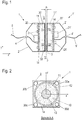
- Figure 1 shows a schematic sectional view of a system according to the application for contactless energy transfer from a primary part 1 to a secondary part 1 '.
- Figure 2 is the primary part 1 in a section along the in Figure 1 shown section line AA reproduced.
- the housings 2 are designed in the form of a half-shell, their front side being closed with a front panel 3. In the rear area, facing away from the front panel 3, a cable bushing 4 for a connection cable 5 is introduced into the housing 2.
- a coil 10 which is wound on a ferrite core 11 or is wound on a coil body which is inserted into the ferrite core 11.
- the coil 10 can be wound with a single conductor. To reduce the skin effect, however, the use of multi-core high-frequency braided wire is preferred.
- the ferrite core 11 is a round pot core on the primary and secondary sides with an outer edge 12 and an inner dome 13 concentric thereto.
- a core is also referred to as a (cylindrically symmetrical) E core.
- the cross-sections of the outer edge 12 and the inner dome 13 are preferably approximately the same size in order to achieve a homogeneous magnetic flux density taking into account the different stray fields in the ferrite core 11.
- the use of ferrite cores with a different geometry is also possible. For example, square or rectangular cores with round or square or rectangular ferrite cores can be used. Coils without coil formers, e.g. with conductors glued together, can also be used.
- the ferrite cores 11 are open towards the respective front plate 3, whereas on the opposite side the outer edge 12 and the inner dome 13 are connected to one another via a pot base.
- the coil 10 is inserted into the here annular trench between the outer edge 12 and the inner dome 13. Any gap that may still be present between the outer and inner edge of the coil 10 and the ferrite core 11 can be filled with a heat-conducting medium.
- the primary part 1 and the secondary part 1 'with their front plates 3, 3' facing one another are brought at a small distance from one another for contactless inductive energy transmission.
- this distance which forms a transmission gap, is shown as transmission distance zo.
- the size of a permissible transmission distance zo is in the range from 0 to a few millimeters or centimeters, depending on the size, in particular the diameter of the coils 10 or ferrite cores 11.
- the direction along the axis of the primary-side coil 10 is hereinafter referred to as the z-direction, the assigned axis referred to as the z-axis.
- the x and y directions or axes run perpendicular to this in the plane of the front panel 3.
- the primary-side coil 10 During operation, the primary-side coil 10, hereinafter also referred to as the primary coil 10, has an alternating current applied to it.
- a resonance circuit is preferably formed from the primary coil 10 and a resonance capacitor, the frequency of which is in the range from a few kilohertz (kHz) to a few hundred kHz, a frequency in the range of a few tens of kHz being particularly preferred.
- the alternating current with which the primary coil 10 is applied is provided by an inverter.
- a pulse width modulation method PWM method
- the inverter is located together with monitoring and control devices on a circuit board 20 within the housing 2 of the primary part 1.
- the secondary coil 10' An energy transfer takes place with a magnetic coupling between the primary coil 10 and the secondary-side coil 10 ', hereinafter referred to as the secondary coil 10'.
- the existing ferrite cores 11 and 11 ' make the coupling particularly efficient.
- a voltage is induced in the secondary coil 10 'which, after rectification, voltage conversion - and, if necessary, voltage stabilization - is available as an output voltage on the connection cable 5' for outputting the transmitted energy.
- the electronic components on the secondary side are also arranged on a circuit board 20 ', with individual electronic components 21' being shown here again by way of example.
- the secondary coil can advantageously have a center tap so that a synchronous rectifier can be used.
- heat-conducting elements for example heat-conducting mats 14 can be arranged between the respective ferrite core 11 and the circuit board 20.
- the electronic components 21 arranged on the circuit board 20 represent a source of loss in the transmission path.
- the heat loss generated by these components 21 is transmitted to the ferrite core 11 via the heat conducting mats 14.
- the ferrite core 11 warms up during operation to a higher operating temperature than would be the case without the thermal coupling to the circuit board 20.
- the losses at a lower temperature in the ferrite core 11 are greater than at a higher temperature over a wide frequency and magnetization range.
- the previously described entry of the power loss of the electronic components as heat into the ferrite core 11 increases its temperature and consequently lowers the power loss in the ferrite core 11 caused by magnetic reversal processes. This improves the overall efficiency of the transmission system. This effect can be used on the primary side as well as on the secondary side.
- the existing ferrite core 11, 11 ' is used as a heat sink for the electronic components 21, 21' due to the thermal coupling, which results in an additional effect in terms of material and thus cost savings.
- a potting compound can also be used, for example, in order to thermally couple the circuit board 20 and the ferrite core 11.
- no interlocking guide or positioning elements are provided that would laterally align the primary part 1 and the secondary part 1 'with one another when they are joined. Due to the lack of such elements, the primary part 1 and the secondary part 1 ′ can also be brought into the operating position or separated from one another by a lateral movement, that is to say a movement in the x and / or y direction. This proves to be particularly advantageous in the automation sector, since an additional axial movement of the primary and secondary parts 1, 1 ′ towards one another is not required to establish or disconnect a connection. Depending on the intended application, such guide or positioning elements can, however, also be provided in alternative configurations.
- the ferrite cores 11, 11 allow a high magnetic flux density, through which an efficient energy transfer is possible even with a small coil volume.
- the transmission is relatively tolerant of a lateral shift the primary part 1 and the secondary part 1 'against each other. This is of great advantage in the automation sector, for example, since high positioning accuracy for establishing a conventional plug-in connection with contacts can be dispensed with.
- the primary part 1 of the energy transmission system for detecting the position of the secondary part 1 ' has at least one magnetic field sensor which determines the stray field of the coils 10, 10'.
- four auxiliary coils 30a, 30b, 30c and 30d are used as magnetic field sensors, which are arranged in four quadrants of the front plate 3 next to the coil 10. Two of the auxiliary coils 30a, 30c or 30b, 30d are symmetrically opposite to the center of the coil 10. The position of the four auxiliary coils 30a, 30b, 30c and 30d is shown in the sectional view of FIG Figure 2 clearly visible. If no explicit reference is made in the following to a single one of the auxiliary coils 30a, 30b, 30c and 30d, the auxiliary coils 30a, 30b, 30c and 30d are collectively identified with the reference symbol 30.
- the auxiliary coils 30 represent receiving coils in which, due to the stray field from the primary and secondary coils 10 or 10 ', a signal is induced which is evaluated by an evaluation circuit on the circuit board 20 of the primary part 1.
- the level of the signals induced in the auxiliary coils 30 is dependent both on the distance zo between the primary and secondary part 1, 1 ′ and on a lateral offset in the x and y directions. This is explained below using the Figures 3 and 4 explained in more detail.
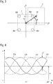
- Figure 3 shows schematically a primary and a secondary part 1, 1 ′ of a system for inductive energy transmission, which are laterally offset to one another.
- the offset is xo in the x direction and yo in the y direction.
- a distance of zo which is not visible in this illustration, can be present between the two parts 1, 1 '.
- the lateral offset xo and yo can also be expressed in polar coordinates and then described via a radial distance ro between the center points of the coils 10 and 10 ', as well as an angle ⁇ between a distance vector and the x-axis.
- Figure 4 shows an example of how signal amplitudes 31 (here voltage amplitudes) change in the four auxiliary coils 30 if the secondary part 1 'is moved in a circle around the z-axis of the primary part 1 with a fixed distance zo and a fixed radial distance ro.
- a resulting respective signal amplitude 31a, 31b, 31c and 31d of the auxiliary coils 30a, 30b, 30c and 30d is shown as a function of the angle ⁇ . It can be seen that, as a first approximation, there is a sinusoidal dependence of the signal amplitude 31 on the angle ⁇ .
- the sinusoids have the same amplitude û and an offset uo that is also the same for all sinusoids.
- the drawn amplitude û depends mainly on the size of the radial distance ro, whereas the offset uo mainly depends on the distance zo between the primary and secondary part 1, 1 '.
- This special dependency which applies when using a ferrite core 11, 11 'in the primary coil 10 or the secondary coil 10', favors and simplifies a separation of the radial distance ro (or the lateral offset xo, yo) and the axial distance zo.
- metallic objects in the vicinity and stray fields from other neighboring components influence the measured signal amplitudes more intensely as the axial distance between the coils increases, which makes it difficult to determine the axial distance zo.
- the dependency is essentially linear, in particular in the case of (compared to the size of the coils 10, 10 ') small values for the radial one Distance ro and the distance zo.
- the proportionality factors for these linear dependencies can be determined beforehand in series of measurements with a constant current of a predetermined level through the primary coil 10 with a known radial distance ro and a known distance z 0 for a given system for energy transmission. Measured values subsequently recorded to determine the distance are then scaled to the conditions when the proportionality factors are recorded with regard to the current level of the current through the primary coil 10.
- the height of the four signal amplitudes 31a, 31b, 31c and 31d is first measured for an unknown distance zo, an unknown radial distance ro and an unknown angle ⁇ .
- the sinusoidal component of the signal amplitudes 31 cancels one another, whereby the size of the offset uo can be determined.
- the offsets uo can also be determined for both pairs of opposing auxiliary coils 31a, 31c and 31b, 31d and thus ultimately by adding up all four signal amplitudes 31a-31d. With the previously determined proportionality factor and scaling to the level of the current current through the primary coil 10, the size of the distance zo follows from the size of the offset uo.
- the size of the angle ⁇ can be determined by forming the difference between two signal amplitudes 31a and 31c or 31b and 31d of two opposing auxiliary coils 30a and 30c or 30b and 30d via angle functions.
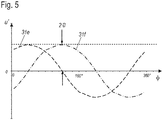
- the differences u 'of two signals in each case are shown as difference amplitudes 31e and 31f, again as a function of the angle ⁇ .
- the difference signal 31e is made up of the signal amplitudes 31a and 31c and the difference signal 31f from the signal amplitudes 31b and 31d.
- the two difference signals 31e and 31f also run sinusoidally with a phase shift of 90 ° to one another.
- the difference signals 31e, 31f show no offset and their signal amplitudes only depend on the offset, i.e. the radial distance ro.
- the magnitude of the radial distance ro follows from one of the amplitudes of the difference signals 31e, 31f.
- the amplitude of the difference signals 31e, 31f is twice as large as that of the amplitude û of the signal amplitudes 31a-d.
- the angle ⁇ i.e. the direction in which the offset is present, can finally be determined via trigonometric functions.
- the phase position of the difference signals 31e or 31f can advantageously be determined at their zero crossing points.
- both the radial distance ro and the direction (angle ⁇ ) of a lateral offset between the primary and secondary part 1,1 can be obtained from the height of the signal induced in them by the stray field of the coils 10, 10 'using the four auxiliary coils 30 'are determined, and also the distance zo between the primary and secondary part 1, 1'.
- the information about the lateral offset can be converted from the polar coordinates (radial distance ro, angle ⁇ ) into Cartesian coordinates (xo, yo) and specified.
- an automation controller can identify a problem with the positioning of the primary and secondary parts 1, 1 ′ with respect to one another, which indicates a fault in a robot that uses the system for energy transfer. It can further be provided that the energy transfer from the primary part 1 to the secondary part 1 'is interrupted or not even established in an initialization step if one is determined lateral offset (xo, yo or ro) and / or a determined distance zo are above defined limit values.
- the limit values can take into account in the form of tables or a functional context to what extent a simultaneous combination of lateral offset and distance is permitted.
- the method shown has the advantage that an incorrectly positioned secondary side is recognized on the primary side. No feedback from the secondary part 1 ′ to the primary part 1 is necessary in order to guarantee safe operation of the primary part 1.
- a safety mechanism based on feedback from a secondary part to a primary part can also be used with regard to positioning.
- the connector can also be provided to determine information about the lateral offset and / or the distance on the basis of a detuning of the resonance circuit via the resonance frequency, possibly in connection with the current flowing in the primary coil.
- This additional measurement can serve as a control measurement for the previously described distance determination via the auxiliary coils 30 in order to additionally increase the transmission reliability.
Landscapes
- Engineering & Computer Science (AREA)
- Power Engineering (AREA)
- Computer Networks & Wireless Communication (AREA)
- Transportation (AREA)
- Mechanical Engineering (AREA)
- Life Sciences & Earth Sciences (AREA)
- Sustainable Development (AREA)
- Sustainable Energy (AREA)
- Measurement Of Length, Angles, Or The Like Using Electric Or Magnetic Means (AREA)
- Charge And Discharge Circuits For Batteries Or The Like (AREA)
- Measuring Magnetic Variables (AREA)
- Near-Field Transmission Systems (AREA)
Description
- Die Erfindung betrifft ein System zur kontaktlosen Energieübertragung von einem Primärteil auf ein Sekundärteil, die jeweils mindestens eine Spule aufweisen, die induktiv miteinander koppelbar sind, wobei anhand eines von den Spulen erzeugten und mit mindestens einem Magnetfeldsensor gemessenen Magnetfelds ein lateraler Versatz des Sekundärteils gegenüber dem Primärteil bestimmt wird. Die Erfindung betrifft weiterhin ein Betriebsverfahren für ein System zur kontaktlosen induktiven Energieübertragung von einer Spule eines Primärteils zu einer Spule eines Sekundärteils.
- Gegenüber Steckverbindern, bei denen eine Energieübertragung über mechanisch zu verbindende bzw. zu trennende Kontaktelemente erfolgt, besitzen kontaktlose Systeme zur Energieübertragung Vorteile bezüglich eines Verschleißes durch eine hohe Zahl von Steckzyklen oder starken Vibrationen. Zudem ist ein Kontaktabbrand bei einem Ein- oder Ausstecken unter elektrischer Last verhindert. Auch die Gefahr des Ausbildens von Lichtbögen beim Trennen von Steckverbindern mit einer hohen Strombelastung ist bei kontaktlosen Systemen zur Energieübertragung nicht gegeben. Schließlich liegt bei der kontaktlosen Übertragung von Energie eine galvanische Trennung zwischen dem Primärteil und dem Sekundärteil vor, die beispielsweise beim Einsatz im medizinischen Bereich gefordert sein kann. Das Fehlen der mechanisch aufwendig ineinander greifenden Kontakte ermöglicht zudem eine Gestaltung des Systems mit möglichst glatten Oberflächen, was die kontaktlosen Systeme zur Energieübertragung geeignet für Anwendungszwecke mit einer erhöhten Anforderung an Sauberkeit/Hygiene prädestiniert, beispielsweise im Lebensmittelbereich.
- Insbesondere die hohe Verschleißfestigkeit macht eine kontaktlose induktive Energieübertragung auch im Automatisierungsbereich interessant, beispielsweise zur Übertragung von Energie an ein Wechselwerkzeug eines Roboters.
- Die Druckschrift
WO 2013/087676 A2 beschreibt ein System zur kontaktlosen induktiven Energieübertragung von einem Primärteil zu einem Sekundärteil, die eine mechanische Steckvorrichtung zur Energieübertragung beispielsweise an ein Wechselwerkzeug eines Roboters ersetzen kann. Primär- und Sekundärteil weisen jeweils mindestens eine Spule auf, die induktiv miteinander koppelbar sind und die jeweils mit einem Ferritkern zusammenwirken. Der Ferritkern erhöht den magnetischen Fluss durch seine Permeabilität derart, dass auch bei kleinen Baugrößen des Systems und kleinen Übertragungsflächen hohe elektrische Leistungen übertragen werden können. - Eine Energieübertragung ist durch den hohen magnetischen Fluss dabei auch dann bereits möglich, wenn das Primär- und das Sekundärteil sich (noch) nicht in einer Position befinden, in der der Abstand zwischen ihnen minimal ist, sondern wenn ein Spalt zwischen ihnen besteht. Ebenso kann eine Energieübertragung auch bei einem gewissen seitlichen (lateralen) Versatz von Primär- und Sekundärteil erfolgen, also wenn sich die Spulen von Primär- und das Sekundärteil nicht auf einer gemeinsamen Achse befinden. Ein zu großer Abstand und/oder ein zu großer seitlicher Versatz beeinflusst jedoch die maximal übertragbare Leistung. Auch wenn eine Versorgung eines angeschlossenen Geräts in manchen Betriebszuständen des Geräts trotz eines seitlichen Versatzes oder eines großen Abstands möglich ist, kann es in anderen Betriebszuständen, in denen ein höherer Leistungsbedarf vorliegt, zu unvorhersehbaren Betriebsstörungen des Geräts kommen, da die geforderte Leistung nicht übertragen werden kann.
- Die Druckschrift
US 2010/0201315 A1 beschreibt ebenfalls eine Anordnung zur induktiven Energieübertragung. Die Anordnung ist insbesondere als kabellose Ladevorrichtung für Mobilgeräte geeignet. Ein Primärteil der Anordnung kann beispielsweise unterhalb einer Tischplatte montiert werden, so dass ein Mobilgerät, beispielsweise ein Mobiltelefon, das ein Sekundärteil der Anordnung aufweist, durch einfaches Auflegen auf die Tischplatte geladen werden kann. - Im Primär- oder im Sekundärteil sind um die entsprechende Spule herum Hilfsspulen angeordnet, die als Magnetfeldsensoren wirken. Aus der Größe der Magnetfelder, die durch die Hilfsspulen gemessen werden, wird ein lateraler Versatz zwischen Primär- und Sekundärteil ermittelt und dem Benutzer angezeigt, so dass dieser das Mobilgerät und damit das Sekundärteil lateral ausgerichtet zum Primärteil positionieren kann. Alternativ wird der maximal mögliche Ladestrom ermittelt und es wird signalisiert, wenn dieser oberhalb eines vorgegebenen Schwellenwertes liegt. Ein entsprechendes Signal zeigt dem Benutzer dann eine zumindest ausreichend gute laterale Positionierung des Mobilgeräts an.
- Die Druckschrift
US 2012/0262002 A1 beschreibt eine Anordnung mit einem bodenmontierten Primärteil und einem Sekundärteil, das an einer Unterseite eines Elektrofahrzeugs angeordnet ist. Beide Teile weisen Spulen auf, über die Energie an das Fahrzeug übertragen werden kann, wenn die Spulen übereinander stehen. Am Sekundärteil sind drei gekreuzte Hilfsspulen angeordnet, mit deren Hilfe beim Annähern des Fahrzeugs an das Primärteil ein von der Primärspule erzeugtes Feld in drei Raumrichtungen vermessen wird. Aus den Messwerten wird eine Richtungsanweisung generiert, mit deren Hilfe ein Fahrzeugführer das Fahrzeug in Richtung des Sekundärteils bewegen und lateral korrekt positionieren kann. - Die beschriebenen Verfahren bieten in Anwendungen, bei denen es auf eine hohe Verfügbarkeit der versorgten Komponenten und höhere übertragene Leistungen ankommt, beispielsweise bei Industrierobotern, jedoch keine ausreichende Funktionssicherheit, da Abstandsvariationen zu einer abrupten Übertragungsunterbrechung führen können.
- Aus der Druckschrift
JP 2013/078198 A JP 2013/031315 A - Es ist eine Aufgabe der vorliegenden Erfindung, unvorhersehbare Betriebsstörungen bei einer Versorgung eines Geräts durch ein eingangs genanntes System zur kontaktlosen Energieübertragung durch eine Abstandsbestimmung zwischen den Spulen zur Energieübertragung möglichst vollständig auszuschalten, ohne die Energieübertragung zu beeinflussen.
- Diese Aufgabe wird durch ein System bzw. ein Betriebsverfahren für ein solches System mit den jeweiligen Merkmalen der unabhängigen Ansprüche gelöst. Vorteilhafte Ausgestaltungen und Weiterbildungen des Systems und des Betriebsverfahrens sind in den abhängigen Ansprüchen angegeben.
- Ein System zur kontaktlosen induktiven Energieübertragung der eingangs genannten Art zeichnet sich dadurch aus, dass das System dazu eingerichtet ist, anhand des von dem mindestens einen Magnetfeldsensor gemessenen Magnetfelds zudem einen Abstand entlang einer Achse der primärseitigen Spule vom Sekundärteil zum Primärteil zu bestimmen, wobei das von dem mindestens einen Magnetfeldsensor gemessene Magnetfeld ein während der Energieübertragung erzeugtes Streufeld der mindestens eine Spule des Primärteils und der mindestens einen Spule des Sekundärteils ist.
- Die zur Energieübertragung verwendeten Spulen des Primärteils und des Sekundärteils erzeugen ein Streufeld, das erfindungsgemäß zur vollständigen Positionsbestimmung des Sekundärteils relativ zum Primärteil verwendet wird.
- Durch Bestimmung des axialen Abstands und nicht nur des lateralen Versatzes kann jegliche, auch beginnende Positionierungsungenauigkeit des Sekundärteils gegenüber dem Primärteil rechtzeitig erkannt werden. Die bestimmte Position kann z.B. über ein Netzwerk an eine Steuereinrichtung beispielsweise einer Automatisierungsanlage übertragen werden. Bei Abweichungen von einer Sollposition kann dann ein Benutzer oder Bediener informiert werden um ggf. die Positionierung des Sekundärteils gegenüber dem Primärteil zu justieren.
- Eine Positionsbestimmung setzt üblicherweise den Einsatz eines Senders für ein Testsignal und eines Empfängers für das Testsignal voraus. Durch die Verwendung des Streufelds der Spulen für die Energieübertragung wird ein sowieso vorhandenes Signal als Testsignal benutzt, wodurch auf den Sender für das Testsignal verzichtet werden kann. Die Positionsbestimmung kann durch Hinzufügen nur eines Empfängers für das Testsignal, dem mindestens einen Magnetfeldsensor, umgesetzt werden.
- In einer vorteilhaften Ausgestaltung des Systems ist der mindestens eine Magnetfeldsensor mindestens eine Hilfsspule, in der die Spulen ein Signal induzieren. Zur Energieübertragung wird ein magnetisches Wechselfeld eingesetzt. Eine Magnetfeldmessung kann somit besonders einfach mithilfe einer Hilfsspule erfolgen.
- In einer weiteren vorteilhaften Ausgestaltung des Systems ist der mindestens eine Magnetfeldsensor im Primärteil angeordnet. So kann die Information über die Positionierung des Sekundärteils unmittelbar im Primärteil ermittelt werden, wobei keine Rückmeldung von dem Sekundärteil an das Primärteil notwendig ist, um ein sicheres Betreiben des Primärteils zu garantieren. Das Primärteil kann als stationäres Teil der Übertragungseinrichtung auch datentechnisch mit einer Automatisierungssteuerung verbunden sein und die Positionsinformation an die Automatisierungssteuerung weitergeben.
- In einer weiteren vorteilhaften Ausgestaltung des Systems ist der mindestens eine Magnetfeldsensor im Primär- oder Sekundärteil seitlich versetzt zu der jeweiligen Spule angeordnet. Bevorzugt sind mindestens zwei Magnetfeldsensoren in dem Primär- und/oder Sekundärteil vorgesehen, die paarweise symmetrisch um eine Längsachse der jeweiligen Spule angeordnet sind. Besonders bevorzugt sind vier Magnetfeldsensoren in dem Primär- und/oder Sekundärteil um die jeweilige Spule herum angeordnet. Bei der paarweisen Anordnung können Signale der Magnetfeldsensoren miteinander verglichen werden bzw. Differenzen der Signale betrachtet werden, die für einen seitlichen Versatz maßgeblich sind. Durch den Einsatz von vier Sensoren können ein Abstand von Primär- und Sekundärteil und ein seitlicher Versatz in jede Richtung bestimmt werden. In alternativen Ausgestaltungen können auch mehr als vier Magnetfeldsensoren eingesetzt werden, beispielsweise um eine Genauigkeit, mit der Abstand und/oder Versatz bestimmt werden können, weiter zu steigern.
- Ein erfindungsgemäßes Betriebsverfahren für ein System zur kontaktlosen induktiven Energieübertragung von einer Spule eines Primärteils zu einer Spule eines Sekundärteils zeichnet sich dadurch aus, dass anhand eines von den Spulen während der Energieübertragung erzeugten und mit mindestens einem Magnetfeldsensor gemessenen Magnetfelds sowohl der laterale Versatz als auch der axiale Abstand des Sekundärteils zum Primärteil bestimmt wird. Es ergeben sich die im Zusammenhang mit dem Systems beschriebenen Vorteile.
- Bei einer vorteilhaften Ausgestaltung des Betriebsverfahrens wird die relative Position anhand von Messwerten von vier Magnetfeldsensoren ermittelt, die in dem Primärteil um dessen Spule herum angeordnet sind. Durch den Einsatz von vier Sensoren können ein Abstand von Primär- und Sekundärteil und ein seitlicher Versatz in jede Richtung bestimmt werden. Bevorzugt wird als mindestens ein Magnetfeldsensor mindestens eine Hilfsspule eingesetzt, wobei ein in der mindestens einen Hilfsspule induziertes Signal gemessen wird. Weiter bevorzugt wird als Signal eine Signalamplitude, insbesondere eine Spannungsamplitude, der mindestens einen Hilfsspule ausgewertet.
- Bei einer weiteren vorteilhaften Ausgestaltung des Betriebsverfahrens werden die Signalamplituden von jeweils zwei paarweise gegenüberliegenden Hilfsspulen miteinander verrechnet, um den lateralen Versatz des Sekundärteils gegenüber dem Primärteil zu bestimmen und um den axialen Abstand vom Sekundärteil zum Primärteil zu bestimmen. Bevorzugt umfasst der laterale Versatz einen radialen Abstand zwischen Achsen der Spulen sowie einen Winkel zwischen einem Abstandsvektor, der von der Achse der Spule des Primärteils zu der Achse der Spule des Sekundärteils reicht, und einer definierten Raumrichtung umfasst. Der Versatz wird so in Polarkoordinaten angegeben, woraus der seitliche Abstand der Spulenachsen unmittelbar hervorgeht, als und auch die Richtung, in der das Sekundärteil gegenüber dem Primärteil verschoben ist. Die Richtung, in der der Versatz vorliegt, kann beispielsweise bei einem sich gegenüber dem Primärteil drehenden Sekundärteil Information über eine eventuell vorliegende Unwucht der Drehung geben, auch wenn der Absolutwert des seitlichen Abstands der Spulenachsen konstant ist.
- Bei einer weiteren vorteilhaften Ausgestaltung des Betriebsverfahrens wird eine Energieübertragung von dem Primärteil zu dem Sekundärteil unterbunden, wenn der laterale Versatz des Sekundärteils gegenüber dem Primärteil und/oder der Abstand vom Sekundärteil zum Primärteil, d.h. die Größe des Luftspalts, einen vorgegebenen Grenzwert überschreitet. Auf diese Weise kann eine störungsfreie Energieübertragung bis hin zur spezifizierten Maximalleistung sichergestellt werden. Die Grenzwerte können dabei in Form von Tabellen oder einem Funktionszusammenhang berücksichtigen, inwieweit eine gleichzeitig vorliegende Kombination von seitlichem Versatz und Abstand zugelassen sind.
- Die Erfindung wird nachfolgend anhand von Ausführungsbeispielen mithilfe von fünf Figuren näher erläutert. Die Figuren zeigen:
- Figur 1
- eine Schnittansicht eines Systems zur kontaktlosen Energieübertragung;
- Figur 2
- eine weitere Schnittansicht des in
Figur 1 dargestellten Systems, - Figur 3
- eine schematische Darstellung eines Systems zur kontaktlosen Energieübertragung mit einem seitlichen Versatz zwischen Primär- und Sekundärteil;
- Figur 4
- ein Diagramm, in dem die Höhe von Signalen von Hilfsspulen zur Positionserfassung in Abhängigkeit eines Winkels eines seitlichen Versatzes dargestellt ist; und
- Figur 5
- ein Diagramm, in dem Differenzen der Signale der Hilfsspulen zur Positionserfassung in Abhängigkeit eines Winkels eines seitlichen Versatzes dargestellt sind.
-
Figur 1 zeigt ein schematisches Schnittbild eines anmeldungsgemäßen Systems zur kontaktlosen Energieübertragung von einem Primärteil 1 zu einem Sekundärteil 1'. InFigur 2 ist das Primärteil 1 in einem Schnitt entlang der inFigur 1 dargestellten Schnittlinie A-A wiedergegeben. - Elemente, die dem Primärteil 1 zugeordnet sind, im Folgenden auch primärseitige Elemente genannt, tragen in den Figuren Bezugszeichen ohne Apostroph. Elemente, die dem Sekundärteil 1' zugeordnet sind, im Folgenden auch sekundärseitige Elemente genannt, tragen Bezugszeichen mit einem entsprechenden Apostroph. Dabei sind primärseitige und sekundärseitige Elemente, die die gleiche oder eine vergleichbare Funktion aufweisen, mit Bezugszeichen mit denselben Zahlen versehen. Wenn im Folgenden nicht explizit auf die Primär- oder Sekundärseite verwiesen wird, werden Bezugszeichen ohne Apostroph verwendet, die sich auf beide Seiten beziehen.
- Primärteil 1 und Sekundärteil 1' weisen jeweils ein Gehäuse 2 auf, das aus einem für Steckergehäuse üblichen Material wie Kunststoff, Aluminium oder Edelstahl oder dergleichen gefertigt sein kann. Die Gehäuse 2 sind halbschalenförmig ausgeführt, wobei ihre vordere Seite mit einer Frontplatte 3 verschlossen ist. Im hinteren Bereich, von der Frontplatte 3 weg weisend, ist in das Gehäuse 2 eine Kabeldurchführung 4 für ein Anschlusskabel 5 eingebracht.
- Unmittelbar hinter der Frontplatte 3 ist jeweils eine Spule 10 angeordnet, die auf einen Ferritkern 11 gewickelt ist, bzw. auf einen Spulenkörper gewickelt ist, der in den Ferritkern 11 eingelegt ist. Die Spule 10 kann mit einem einzelnen Leiter gewickelt sein. Zur Verringerung des Skin-Effekts ist allerdings eine Verwendung von mehradriger Hochfrequenzlitze bevorzugt.
- Im dargestellten Ausführungsbeispiel ist der Ferritkern 11 primär- und sekundärseitig ein runder Topfkern mit einem äußeren Rand 12 und einem dazu konzentrischen inneren Dom 13. Ein solcher Kern wird auch als (zylindersymmetrischer) E-Kern bezeichnet. Dabei sind die Querschnitte des äußeren Rands 12 und des inneren Doms 13 bevorzugt näherungsweise gleich groß, um eine homogene magnetische Flussdichte unter Berücksichtigung der unterschiedlichen Streufelder im Ferritkern 11 zu erzielen. Die Verwendung von Ferritkernen mit anderer Geometrie ist ebenfalls möglich. Beispielsweise können quadratische oder rechteckige Kerne mit runden oder quadratischen bzw. rechteckigen Ferritkernen eingesetzt werden. Auch Spulen ohne Spulenkörper, z.B. mit miteinander verklebten Leitern können verwendet werden.
- Zur jeweiligen Frontplatte 3 hin sind die Ferritkerne 11 offen, wohingegen auf der gegenüberliegenden Seite der äußere Rand 12 und der innere Dom 13 über einen Topfboden miteinander verbunden sind. Die Spule 10 ist jeweils in den hier ringförmigen Graben zwischen dem äußeren Rand 12 und dem inneren Dom 13 eingelegt. Ein eventuell noch vorhandener Spalt zwischen dem äußeren und inneren Rand der Spule 10 und dem Ferritkern 11 kann mit einem wärmeleitenden Medium ausgefüllt sein.
- Im Betrieb werden zur kontaktlosen induktiven Energieübertragung das Primärteil 1 und das Sekundärteil 1' mit ihren Frontplatten 3, 3' aufeinander zuweisend in geringem Abstand zu einander gebracht. In der
Figur 1 ist dieser Abstand, der einen Übertragungsspalt bildet, als Übertragungsabstand zo eingezeichnet. Die Größe eines zulässigen Übertragungsabstands zo liegt im Bereich von 0 bis einigen Millimetern oder Zentimetern, abhängig von der Größe, insbesondere dem Durchmesser der Spulen 10 bzw. Ferritkerne 11. Die Richtung entlang der Achse der primärseitigen Spule 10 wird nachfolgend als z-Richtung, die zugeordnete Achse als z-Achse bezeichnet. Senkrecht dazu verlaufen in der Ebene der Frontplatte 3 die x- und y-Richtungen bzw. Achsen. - Im Betrieb wird die primärseitige Spule 10, nachfolgend auch als Primärspule 10 bezeichnet, mit einem Wechselstrom beaufschlagt. Bevorzugt ist dabei aus der Primärspule 10 und einem Resonanzkondensator ein Resonanzkreis gebildet, dessen Frequenz im Bereich von einigen Kilohertz (kHz) bis einigen hundert kHz liegt, wobei eine Frequenz im Bereich von einigen zehn kHz besonders bevorzugt ist. Der Wechselstrom, mit der die Primärspule 10 beaufschlagt wird, wird von einem Wechselrichter bereitgestellt. Im Wechselrichter kann zur Erzeugung der Wechselspannung dabei beispielsweise ein Pulsweitenmodulationsverfahren (PWM-Verfahren) eingesetzt werden. Der Wechselrichter befindet sich zusammen mit Überwachungs- und Steuereinrichtungen auf einer Platine 20 innerhalb des Gehäuses 2 des Primärteils 1. In der Figur sind beispielhaft auf der Platine 20 elektronische Komponenten 21 eingezeichnet. Zum Schutze des Wechselrichters vor einer Resonanzüberhöhung der Amplitude am Resonanzkreis, gebildet aus dem genannten Resonanzkondensator und der Primärspule 10, wird der Resonanzkreis leicht überresonant, also bei Frequenzen oberhalb der Resonanzfrequenz, betrieben.
- Eine Energieübertragung erfolgt bei magnetischer Kopplung zwischen der Primärspule 10 und sekundärseitigen Spule 10', nachfolgend Sekundärspule 10' genannt. Durch die vorhandenen Ferritkerne 11 und 11' ist die Kopplung besonders effizient. In der Sekundärspule 10' wird eine Spannung induziert, die nach Gleichrichtung, Spannungswandlung - und ggf. Spannungsstabilisierung - als Ausgangsspannung am Anschlusskabel 5' zur Abgabe der übertragenen Energie bereitsteht. Die elektronischen Komponenten auf der Sekundärseite sind ebenfalls auf einer Platine 20' angeordnet, wobei hier wiederum beispielhaft einzelne elektronische Komponenten 21' eingezeichnet sind. Vorteilhaft kann die Sekundärspule einen Mittelabgriff aufweisen, so dass ein Synchrongleichrichter verwendet werden kann.
- Sowohl beim Primärteil 1 als auch beim Sekundärteil 1' können zwischen dem jeweiligen Ferritkern 11 und der Platine 20 wärmeleitende Elemente, z.B. Wärmeleitmatten 14, angeordnet sein. Insbesondere bei der Primärseite, aber auch bei der Sekundärseite stellen die auf der Platine 20 angeordneten elektronischen Bauteile 21 eine Verlustquelle im Übertragungsweg dar. Die von diesen Bauelementen 21 erzeugte Verlustwärme wird über die Wärmeleitmatten 14 auf den Ferritkern 11 übertragen. Dadurch wärmt sich der Ferritkern 11 im Betrieb auf eine höhere Betriebstemperatur auf, als dieses ohne die thermische Kopplung an die Platine 20 der Fall wäre.
- Bei geeigneten Ferritmaterialien für die Ferritkerne 11 sind über einem weiten Frequenz- und Magnetisierungsbereich die Verluste bei geringerer Temperatur im Ferritkern 11 größer als bei höherer Temperatur. Der zuvor beschriebene Eintrag der Verlustleistung der elektronischen Komponenten als Wärme in den Ferritkern 11 erhöht dessen Temperatur und senkt folglich die durch Ummagnetisierungsvorgänge hervorgerufene Verlustleistung im Ferritkern 11. Dadurch wird der Gesamtwirkungsgrad des Übertragungssystems verbessert. Dieser Effekt kann sowohl auf der Primärseite als auch auf der Sekundärseite genutzt werden. Gleichzeitig wird der vorhandene Ferritkern 11, 11' durch die thermische Kopplung als Kühlkörper für die Elektronikkomponenten 21, 21' eingesetzt, wodurch sich als zusätzlicher Effekt eine Material- und somit Kosteneinsparung ergibt. Anstelle der Wärmeleitmatten 14 kann beispielsweise auch eine Vergussmasse eingesetzt werden, um die Platine 20 und den Ferritkern 11 thermisch zu koppeln.
- Bei dem dargestellten Ausführungsbeispiel sind keine ineinandergreifenden Führungs- oder Positionierungselemente vorgesehen, die das Primärteil 1 und das Sekundärteil 1' bei einem Zusammenfügen lateral zueinander ausrichten würden. Durch das Fehlen solcher Elemente können das Primärteil 1 und das Sekundärteil 1' auch durch eine Lateralbewegung, das heißt eine Bewegung in x- und/oder y-Richtung in die Betriebsposition gebracht werden bzw. von einander getrennt werden. Dieses erweist sich gerade im Automatisierungsbereich als besonders vorteilhaft, da eine zusätzliche axiale Bewegung von Primär- und Sekundärteil 1,1' aufeinander zu zum Etablieren oder Trennen einer Verbindung nicht erforderlich ist. Je nach geplantem Anwendungszweck können in alternativen Ausgestaltungen derartige Führungs- oder Positionierungselemente jedoch auch vorgesehen sein.
- Die Ferritkerne 11, 11' erlauben eine hohe magnetische Flussdichte, durch die eine effiziente Energieübertragung auch bei kleinem Spulenvolumen möglich ist. Die Übertragung ist dabei relativ tolerant gegenüber einer lateralen Verschiebung des Primärteils 1 und des Sekundärteils 1' gegeneinander. Dieses ist beispielsweise im Automatisierungsbereich von hohem Vorteil, da auf eine hohe Positioniergenauigkeit zur Etablierung einer konventionellen kontaktbehafteten Steckverbindung verzichtet werden kann.
- Dennoch ist eine Kenntnis der Position des Sekundärteils 1' gegenüber dem Primärteil 1 vorteilhaft, um ausschließen zu können, dass eine Übertragung, die bei kleinen Leistungen initiiert werden kann, nicht im Betrieb bei höheren zu übertragenden Leistungen unerwartet zusammenbricht. Außerdem deutet eine sich ändernde Position der beiden Teile zueinander auf eventuelle mechanische oder elektromechanische Probleme z.B. bei dem Roboter, bei dem das System zur Energieübertragung verwendet wird, hin und kann daher eine für die Betriebssicherheit relevante Information darstellen.
- Anmeldungsgemäß weist das Primärteil 1 des Systems zur Energieübertragung zur Positionserkennung des Sekundärteils 1' mindestens einen Magnetfeldsensor auf, der das Streufeld der Spulen 10, 10' ermittelt. Im dargestellten Ausführungsbeispiel sind vier Hilfsspulen 30a, 30b, 30c und 30d als Magnetfeldsensoren eingesetzt, die in vier Quadranten der Frontplatte 3 neben der Spule 10 angeordnet sind. Je zwei der Hilfsspulen 30a, 30c bzw. 30b, 30d liegen sich symmetrisch zum Mittelpunkt der Spule 10 gegenüber. Die Position der vier Hilfsspulen 30a, 30b, 30c und 30d ist im Schnittbild der
Figur 2 gut zu erkennen. Wenn im Folgenden nicht explizit auf eine einzelne der Hilfsspulen 30a, 30b, 30c und 30d Bezug genommen wird wird, werden die Hilfsspulen 30a, 30b, 30c und 30d zusammenfassend mit dem Bezugszeichen 30 gekennzeichnet. - Die Hilfsspulen 30 stellen Empfangsspulen dar, in denen bedingt durch das Streufeld von Primär- und Sekundärspule 10 bzw. 10' jeweils ein Signal induziert wird, das von einer Auswerteschaltung auf der Platine 20 des Primärteils 1 ausgewertet wird. Die Höhe der in den Hilfsspulen 30 induzierten Signale ist sowohl von dem Abstand zo zwischen Primär- und Sekundärteil 1,1' abhängig, als auch von einem lateralen Versatz in x- und y-Richtung. Dieses wird nachfolgend anhand der
Figuren 3 und 4 detaillierter erläutert. -
Figur 3 zeigt schematisch ein Primär- und ein Sekundärteil 1,1' eines Systems zur induktiven Energieübertragung, die zueinander seitlich (lateral) versetzt sind. In kartesischen Koordinaten beträgt der Versatz xo in x-Richtung und yo in y-Richtung. Zusätzlich kann ein in dieser Darstellung nicht sichtbarer Abstand von zo zwischen den beiden Teilen 1,1' vorliegen. Der laterale Versatz xo und yo kann auch in Polarkoordinaten ausgedrückt werden und dann über einen radialen Abstand ro der Mittelpunkte der Spulen 10 bzw. 10' beschrieben werden, sowie einen Winkel φ zwischen einem Abstandsvektor und der x-Achse. -
Figur 4 zeigt beispielhaft, wie sich Signalamplituden 31 (hier Spannungsamplituden) in den vier Hilfsspulen 30 ändern, wenn bei festem Abstand zo und betragsmäßig festem radialen Abstand ro das Sekundärteil 1' kreisförmig um die z-Achse des Primärteils 1 herum bewegt wird. Es ist eine sich ergebende jeweilige Signalamplitude 31a, 31b, 31c und 31d der Hilfsspulen 30a, 30b, 30c und 30d abhängig vom Winkel φ dargestellt. Es zeigt sich, dass in erster Näherung eine jeweils sinusförmige Abhängigkeit der Signalamplitude 31 von dem Winkel φ besteht. Die Sinuskurven weisen eine gleiche Amplitude û und einen ebenfalls für alle Sinuskurven gleichen Offset uo auf. - Dabei hängt die eingezeichnete Amplitude û überwiegend von der Größe des radialen Abstands ro ab, wohingegen der Offset uo überwiegend von dem Abstand zo zwischen Primär- und Sekundärteil 1, 1' abhängt. Diese spezielle Abhängigkeit, die bei Verwendung eines Ferritkerns 11, 11' bei der Primärspule 10 bzw. der Sekundärspule 10' gilt, begünstigt und vereinfacht eine Trennung des radialen Abstands ro (bzw. des lateralen Versatzes xo, yo) und des axialen Abstand zo. Bei Verwendung von Luftspulen ohne Ferritkern beeinflussen metallische Objekt in der Umgebung und Streufelder anderer benachbarter Komponenten die gemessenen Signalamplituden verstärkt mit zunehmendem axialen Abstand der Spulen, was eine Bestimmung des axialen Abstand zo erschwert.
- In beiden Fällen ist die Abhängigkeit im Wesentlichen linear, insbesondere bei (verglichen mit der Größe der Spulen 10, 10') kleinen Werten für den radialen Abstand ro und den Abstand zo. Die Proportionalitätsfaktoren für diese linearen Abhängigkeiten können in Messreihen bei konstantem Strom einer vorgegebenen Höhe durch die Primärspule 10 mit bekanntem radialen Abstand ro und bekanntem Abstand z0 für ein gegebenes System zur Energieübertragung zuvor ermittelt werden. Nachfolgend aufgenommene Messwerte zur Abstandsbestimmung werden dann im Hinblick auf die dann vorliegende Höhe des Stroms durch die Primärspule 10 auf die Bedingungen bei der Aufnahme der Proportionalitätsfaktoren skaliert.
- Im Betrieb des Systems zur Energieübertragung wird dann für einen unbekannten Abstand zo, einen unbekannten radialen Abstand ro und einen unbekannten Winkel φ zunächst die Höhe der vier Signalamplituden 31a, 31b, 31c und 31d gemessen.
- Durch Addition von zwei Signalamplituden 31a und 31c oder 31b und 31d der gegenüberliegenden Hilfsspulen 30a und 30c oder 30b und 30d hebt sich der sinusförmige Anteil der Signalamplituden 31 gegenseitig auf, wodurch die Größe des Offsets uo ermittelt werden kann. Um ein gutes Signal-zu Rauschverhältnis zu erzielen, kann der Offsets uo auch für beide Paare gegenüberliegender Hilfsspulen 31a, 31c und 31b, 31d und damit letztlich durch die Aufsummierung aller vier Signalamplituden 31a-31d bestimmt werden. Mit dem vorab ermittelten Proportionalitätsfaktor und einer Skalierung auf die Höhe des aktuellen Stroms durch die Primärspule 10 folgt aus der Größe des Offsets uo die Größe des Abstands zo.
- Anschließend kann durch eine Differenzbildung von je zwei Signalamplituden 31a und 31c bzw. 31b und 31d jeweils zweier gegenüberliegender Hilfsspulen 30a und 30c bzw. 30b und 30d über Winkelfunktionen die Größe des Winkels φ bestimmt werden.
- In der
Figur 5 sind die Differenzen u' von jeweils zwei Signalen als Differenzamplituden 31e und 31f wiederum in Abhängigkeit des Winkels φ dargestellt. Das Differenzsignal 31e ist aus den Signalamplituden 31a und 31c gebildet und das Differenzsignal 31f aus den Signalamplituden 31b und 31d. - Die beiden Differenzsignale 31e und 31f verlaufen ebenfalls sinusförmig mit einer Phasenverschiebung von 90° zueinander. Die Differenzsignale 31e, 31f zeigen keinen Offset und die ihre Signalamplituden hängen nur noch vom Versatz, d.h. dem radialen Abstand ro ab. Mit dem vorab ermittelten Proportionalitätsfaktor folgt nach Skalierung auf die Höhe des aktuellen Stroms durch die Primärspule 10 aus einer der Amplituden der Differenzsignale 31e, 31f die Größe des radialen Abstands ro. Die Amplitude der Differenzsignale 31e, 31f ist dabei doppelt so groß wie die der Amplitude û der Signalamplituden 31a-d.
- Aus der Phasenlage einer der Differenzsignale 31e oder 31f kann schließlich über trigonometrische Funktionen der Winkel φ, d.h. die Richtung in der der Versatz vorliegt, bestimmt werden. Die Phasenlage der Differenzsignale 31e oder 31f kann vorteilhaft an ihren Nulldurchgangsstellen ermittelt werden.
- Zusammenfassend kann anmeldungsgemäß mithilfe der vier Hilfsspulen 30 aus der Höhe der in ihnen durch das Streufeld der Spulen 10, 10' induzierte Signal sowohl der radiale Abstand ro, als auch die Richtung (Winkel φ) eines seitlichen Versatzes zwischen Primär- und Sekundärteil 1,1' bestimmt werden, und auch der Abstand zo zwischen Primär- und Sekundärteil 1, 1'. Die Informationen über den lateralen Versatz können aus den Polarkoordinaten (radialer Abstand ro, Winkel φ) auch in kartesischen Koordinaten (xo, yo) umgerechnet und angegeben werden.
- Es kann vorgesehen sein, diese Informationen über seitlichen Versatz und Abstand über einen Datenkanal des Primärteils 1 auszugeben. Anhand dieser Informationen kann beispielsweise von einer Automatisierungssteuerung ein Problem bei der Positionierung von Primär- und Sekundärteil 1,1' zueinander erkannt werden, das auf einen Fehler bei einem Roboter, der das System zur Energieübertragung verwendet, hinweist. Weiter kann vorgesehen sein, die Energieübertragung vom Primärteil 1 zum Sekundärteil 1' zu unterbrechen bzw. bereits in einem Initialisierungsschritt gar nicht erst zu etablieren, wenn ein ermittelter seitlicher Versatz (xo, yo bzw. ro) und/oder ein ermittelter Abstand zo über festgelegten Grenzwerten liegen. Die Grenzwerte können dabei in Form von Tabellen oder einem Funktionszusammenhang berücksichtigen, inwieweit eine gleichzeitig vorliegende Kombination von seitlichem Versatz und Abstand zugelassen sind.
- Das dargestellte Verfahren hat den Vorteil, dass eine nicht korrekt positionierte Sekundärseite primärseitig erkannt wird. Es ist keine Rückmeldung von dem Sekundärteil 1' an das Primärteil 1 notwendig, um ein sicheres Betreiben des Primärteils 1 zu garantieren.
- In einer alternativen Ausgestaltung des Steckverbinders ist ein auf einer Rückmeldung eines Sekundärteils an ein Primärteil basierender Sicherheitsmechanismus im Hinblick auf die Positionierung zusätzlich einsetzbar.
- In einer weiteren alternativen Ausgestaltung des Steckverbinders kann zusätzlich vorgesehen sein, Informationen über den seitlichen Versatz und/oder den Abstand anhand einer Verstimmung des Resonanzkreises über die Resonanzfrequenz ggf. in Verbindung mit dem in der Primärspule fließenden Strom zu ermitteln. Diese zusätzliche Messung kann als Kontrollmessung zur zuvor beschriebenen Abstandsbestimmung über die Hilfsspulen 30 dienen, um die Übertragungssicherheit zusätzlich zu erhöhen.
-
- 1
- Primärteil
- 1'
- Sekundärteil
- 2,2'
- Gehäuse
- 3, 3'
- Abdeckplatte
- 4,4'
- Anschlusskabel
- 5, 5'
- Kabeldurchführung
- 10
- Primärspule
- 10'
- Sekundärspule
- 11, 11'
- Ferritkern
- 12, 12'
- äußerer Rand
- 13, 13'
- innerer Dom
- 14, 14'
- Wärmeleitmatte
- 20,20'
- Platine
- 21, 21'
- elektronische Bauelemente
- 30a-d
- Hilfsspule
- 31a-d
- Signalamplitude
- 31e, 31f
- Differenzsignal
- xo, yo
- seitlicher Versatz (in kartesischen Koordinaten)
- ro
- radialer Abstand (Polarkoordinaten)
- φ
- Winkel (Polarkoordinaten)
- z0
- Abstand
- u
- Höhe der Signalamplitude
- û
- Amplitude
- uo
- Offset
Claims (13)
- System zur kontaktlosen induktiven Energieübertragung von einem Primärteil (1) zu einem Sekundärteil (1'), die jeweils mindestens eine Spule (10, 10') aufweisen, die induktiv miteinander koppelbar sind, wobei das Primärteil (1) und/oder das Sekundärteil (1') mindestens einen Magnetfeldsensor aufweist und dazu eingerichtet ist, anhand eines von den Spulen (10, 10') erzeugten und mithilfe des mindestens einen Magnetfeldsensors gemessenen Magnetfelds einen lateralen Versatz des Sekundärteils (1') gegenüber dem Primärteil (1) zu bestimmen, dadurch gekennzeichnet, dass das System weiter dazu eingerichtet ist, dass das von dem mindestens einen Magnetfeldsensor gemessene Magnetfeld ein während der Energieübertragung erzeugtes Streufeld der mindestens eine Spule (10) des Primärteils (1) und der mindestens einen Spule des Sekundärteils (1') ist und anhand des von dem mindestens einen Magnetfeldsensor gemessenen Streufelds einen Abstand (zo) entlang einer Achse der primärseitigen Spule (10) vom Sekundärteil (1') zum Primärteil (1) zu bestimmen.
- System nach Anspruch 1, bei dem der mindestens eine Magnetfeldsensor mindestens eine Hilfsspule (30) ist, in der die Spulen (10, 10') ein Signal induzieren.
- System nach Anspruch 1 oder 2, bei dem der mindestens eine Magnetfeldsensor im Primärteil (1) angeordnet ist.
- System nach einem der Ansprüche 1 bis 3, bei dem der mindestens eine Magnetfeldsensor im Primär- oder Sekundärteil (1, 1') seitlich versetzt zu der jeweiligen Spule (10, 10') angeordnet ist.
- System nach Anspruch 4, bei dem mindestens zwei Magnetfeldsensoren in dem Primär- und/oder Sekundärteil (1, 1') angeordnet sind, die paarweise symmetrisch um eine Längsachse der jeweiligen Spule (10, 10') angeordnet sind.
- System nach Anspruch 4, bei dem vier Magnetfeldsensoren in dem Primär- und/oder Sekundärteil (1, 1') um die jeweilige Spule (10, 10') herum angeordnet sind.
- Betriebsverfahren für ein System zur kontaktlosen induktiven Energieübertragung von einer Spule (10) eines Primärteils (1) zu einer Spule (10') eines Sekundärteils (1') , wobei anhand eines von den Spulen (10, 10') erzeugten und mit mindestens einem Magnetfeldsensor gemessenen Magnetfelds ein lateraler Versatz des Sekundärteils (1') zum Primärteil (1) bestimmt wird dadurch gekennzeichnet, dass die mindestens eine Spule (10) des Primärteils (1) und die mindestens eine Spule des Sekundärteils (1') während der Energieübertragung ein Streufeld erzeugen, das von dem mindestens einen Magnetfeldsensor gemessen wird, und dass anhand des von dem mindestens einen Magnetfeldsensor gemessenen Streufelds darüber hinaus ein Abstand (zo) entlang einer Achse der primärseitigen Spule (10) vom Sekundärteil (1') zum Primärteil (1) bestimmt wird.
- Betriebsverfahren nach Anspruch 7, bei dem der laterale Versatz und der Abstand (zo) anhand von Messwerten von vier Magnetfeldsensoren ermittelt werden, die in dem Primärteil (1) um dessen Spule (10) herum angeordnet sind.
- Betriebsverfahren nach Anspruch 7 oder 8, bei dem als mindestens ein Magnetfeldsensor mindestens eine Hilfsspule (30) eingesetzt wird, wobei ein in der mindestens einen Hilfsspule (30) induziertes Signal gemessen wird.
- Betriebsverfahren nach Anspruch 9, bei dem als Signal eine Signalamplitude (31), insbesondere eine Spannungsamplitude, der mindestens einen Hilfsspule (30) ausgewertet wird.
- Betriebsverfahren nach Anspruch 10, bei dem die Signalamplituden (31) von jeweils zwei paarweise gegenüberliegenden Hilfsspulen (30) miteinander verrechnet werden, um den lateralen Versatz des Sekundärteils (1') gegenüber dem Primärteil (1) zu bestimmen und um den Abstand (zo) vom Sekundärteil (1') zum Primärteil (1) zu bestimmen.
- Betriebsverfahren nach Anspruch 11, bei dem der laterale Versatz einen radialen Abstand (ro) zwischen Achsen der Spulen (10, 10') sowie einen Winkel (φ) zwischen einem Abstandsvektor, der von der Achse der Spule (10) des Primärteils (1) zu der Achse der Spule (10') des Sekundärteils (1') reicht, und einer definierten Raumrichtung umfasst.
- Betriebsverfahren nach Anspruch 11 oder 12, bei dem eine Energieübertragung von dem Primärteil (1) zu dem Sekundärteil (1') unterbunden wird, wenn der lateralen Versatz des Sekundärteils (1') gegenüber dem Primärteil (1) und/oder der Abstand (zo) vom Sekundärteil (1') zum Primärteil (1) einen vorgegebenen Grenzwert überschreitet.
Applications Claiming Priority (3)
| Application Number | Priority Date | Filing Date | Title |
|---|---|---|---|
| DE102015105359 | 2015-04-09 | ||
| DE102015113723.2A DE102015113723A1 (de) | 2015-04-09 | 2015-08-19 | Vorrichtung zur kontaktlosen induktiven Energieübertragung und Betriebsverfahren für eine derartige Vorrichtung |
| PCT/EP2016/057826 WO2016162520A1 (de) | 2015-04-09 | 2016-04-08 | Vorrichtung zur kontaktlosen induktiven energieübertragung und betriebsverfahren für eine derartige vorrichtung |
Publications (2)
| Publication Number | Publication Date |
|---|---|
| EP3281275A1 EP3281275A1 (de) | 2018-02-14 |
| EP3281275B1 true EP3281275B1 (de) | 2021-10-13 |
Family
ID=56986417
Family Applications (1)
| Application Number | Title | Priority Date | Filing Date |
|---|---|---|---|
| EP16715848.4A Active EP3281275B1 (de) | 2015-04-09 | 2016-04-08 | Vorrichtung zur kontaktlosen induktiven energieübertragung und betriebsverfahren für eine derartige vorrichtung |
Country Status (7)
| Country | Link |
|---|---|
| US (1) | US10505399B2 (de) |
| EP (1) | EP3281275B1 (de) |
| JP (1) | JP2018512837A (de) |
| CN (1) | CN107431386B (de) |
| DE (1) | DE102015113723A1 (de) |
| ES (1) | ES2898674T3 (de) |
| WO (1) | WO2016162520A1 (de) |
Families Citing this family (10)
| Publication number | Priority date | Publication date | Assignee | Title |
|---|---|---|---|---|
| CN108297704A (zh) * | 2017-01-11 | 2018-07-20 | 宁波轩悦行电动汽车服务有限公司 | 电动汽车还车处理系统 |
| DE102017108302A1 (de) | 2017-04-19 | 2018-10-25 | Weidmüller Interface GmbH & Co. KG | Vorrichtung zur kontaktlosen induktiven Energieübertragung und Verfahren zum Betreiben der Vorrichtung |
| DE202017107131U1 (de) * | 2017-11-24 | 2019-01-10 | Bombardier Primove Gmbh | Beweglicher Teil einer Einrichtung zur induktiven Energieübertragung sowie Einrichtung zur induktiven Energieübertragung |
| US10790711B2 (en) * | 2017-12-21 | 2020-09-29 | Korea Advanced Institute Of Science And Technology | Magnetic field generating apparatus having cannon shape and magnetic field generation method thereof |
| DE102018120779B3 (de) | 2018-08-24 | 2019-12-12 | Phoenix Contact Gmbh & Co. Kg | Kontaktloses PoE-Verbindungssystem |
| CN109883309B (zh) * | 2019-01-28 | 2021-04-27 | 中国船舶重工集团公司第七一五研究所 | 一种基于磁性感应原理的缆绳到位传感装置 |
| CN109895643B (zh) * | 2019-02-26 | 2020-07-07 | 浙江大学 | 一种基于差分电感的在线式电动汽车无线充电定位系统 |
| US11505077B2 (en) * | 2020-05-27 | 2022-11-22 | Toyota Motor Engineering & Manufacturing North America, Inc. | Systems and methods for wireless vehicle power transfer and misalignment estimation |
| CN114050665B (zh) * | 2022-01-17 | 2022-04-12 | 广东电网有限责任公司佛山供电局 | 一种用于三相电缆在线监测的工作电源 |
| DE102023126699A1 (de) * | 2023-09-29 | 2025-04-03 | Mahle International Gmbh | Induktive Ladeeinrichtung für ein Fahrzeug |
Citations (2)
| Publication number | Priority date | Publication date | Assignee | Title |
|---|---|---|---|---|
| JP2013031315A (ja) * | 2011-07-29 | 2013-02-07 | Toko Inc | ワイヤレス電力伝送装置および相対位置検出方法 |
| JP2013078198A (ja) * | 2011-09-30 | 2013-04-25 | Toko Inc | ワイヤレス電力伝送装置および相対位置検出方法 |
Family Cites Families (16)
| Publication number | Priority date | Publication date | Assignee | Title |
|---|---|---|---|---|
| CN101160703B (zh) | 2005-04-12 | 2011-06-15 | 先进装配系统有限责任两合公司 | 用于无接触电流供电装置的初级部件和电流供电装置 |
| JP2009089465A (ja) * | 2007-09-27 | 2009-04-23 | Panasonic Corp | 充電器および充電システム |
| CN101809842A (zh) * | 2007-09-27 | 2010-08-18 | 松下电器产业株式会社 | 电子装置、充电器和充电装置 |
| JP2010130729A (ja) * | 2008-11-25 | 2010-06-10 | Canon Inc | 充電装置、送電装置及び非接触充電システム |
| US20130207893A1 (en) * | 2009-04-29 | 2013-08-15 | Kye Systems Corp. | Positioning input system with wireless charging function, and device |
| US8473066B2 (en) * | 2009-07-06 | 2013-06-25 | Boston Scientific Neuromodulation Company | External charger for a medical implantable device using field sensing coils to improve coupling |
| JP2012034546A (ja) * | 2010-08-03 | 2012-02-16 | Panasonic Corp | 無線電力伝送システム |
| US10090885B2 (en) * | 2011-04-13 | 2018-10-02 | Qualcomm Incorporated | Antenna alignment and vehicle guidance for wireless charging of electric vehicles |
| DE102011056265A1 (de) | 2011-12-12 | 2013-06-13 | Weidmüller Interface GmbH & Co. KG | Steckvorrichtung zur kontaktlosen induktiven Energieübertragung und Betriebsverfahren für eine solche Steckvorrichtung |
| FR2989529B1 (fr) * | 2012-04-12 | 2016-04-15 | Continental Automotive France | Procede et banc de charge par couplage magnetique |
| JP6059522B2 (ja) * | 2012-04-17 | 2017-01-11 | 日東電工株式会社 | 無線電力供給システム、給電装置、受電装置、及び、磁界空間の形成方法 |
| KR101949127B1 (ko) | 2013-08-01 | 2019-02-18 | 삼성전자주식회사 | 하이브리드 동기화 기법을 적용한 무선 에너지 수신 방법 및 장치 |
| JP6125948B2 (ja) * | 2013-08-12 | 2017-05-10 | 本田技研工業株式会社 | 非接触充電装置 |
| US9537353B1 (en) * | 2014-06-03 | 2017-01-03 | Apple Inc. | Methods for detecting mated coils |
| US9829599B2 (en) * | 2015-03-23 | 2017-11-28 | Schneider Electric USA, Inc. | Sensor and method for foreign object detection in induction electric charger |
| US10034704B2 (en) * | 2015-06-30 | 2018-07-31 | Ethicon Llc | Surgical instrument with user adaptable algorithms |
-
2015
- 2015-08-19 DE DE102015113723.2A patent/DE102015113723A1/de not_active Withdrawn
-
2016
- 2016-04-08 WO PCT/EP2016/057826 patent/WO2016162520A1/de not_active Ceased
- 2016-04-08 ES ES16715848T patent/ES2898674T3/es active Active
- 2016-04-08 JP JP2017552961A patent/JP2018512837A/ja active Pending
- 2016-04-08 EP EP16715848.4A patent/EP3281275B1/de active Active
- 2016-04-08 US US15/557,265 patent/US10505399B2/en active Active
- 2016-04-08 CN CN201680018030.2A patent/CN107431386B/zh active Active
Patent Citations (2)
| Publication number | Priority date | Publication date | Assignee | Title |
|---|---|---|---|---|
| JP2013031315A (ja) * | 2011-07-29 | 2013-02-07 | Toko Inc | ワイヤレス電力伝送装置および相対位置検出方法 |
| JP2013078198A (ja) * | 2011-09-30 | 2013-04-25 | Toko Inc | ワイヤレス電力伝送装置および相対位置検出方法 |
Also Published As
| Publication number | Publication date |
|---|---|
| US20180062444A1 (en) | 2018-03-01 |
| CN107431386B (zh) | 2021-05-07 |
| CN107431386A (zh) | 2017-12-01 |
| ES2898674T3 (es) | 2022-03-08 |
| US10505399B2 (en) | 2019-12-10 |
| DE102015113723A1 (de) | 2016-10-13 |
| JP2018512837A (ja) | 2018-05-17 |
| WO2016162520A1 (de) | 2016-10-13 |
| EP3281275A1 (de) | 2018-02-14 |
Similar Documents
| Publication | Publication Date | Title |
|---|---|---|
| EP3281275B1 (de) | Vorrichtung zur kontaktlosen induktiven energieübertragung und betriebsverfahren für eine derartige vorrichtung | |
| EP3523816B1 (de) | Vorrichtung zur kontaktlosen induktiven energieübertragung und betriebsverfahren für eine derartige vorrichtung | |
| EP2895889B1 (de) | Metall-fremdkörper-erkennungssystem für induktive energieübertragungssysteme | |
| EP2791950B1 (de) | Steckvorrichtung zur kontaktlosen induktiven energieübertragung und betriebsverfahren für eine solche steckvorrichtung | |
| EP3008474B1 (de) | Stromsensoranordnung mit messspulen | |
| DE112012003875T5 (de) | Kontaktlose Stromversorungsvorrichtung | |
| EP2550174A2 (de) | System zur berührungslosen energieübertragung an ein fahrzeug | |
| DE102014202747A1 (de) | Vorrichtung zum Erfassung einer Lageabweichung der passiven Spule gegenüber der Primärspule eines induktiven Ladesystems für ein Fahrzeug sowie zugehöriges Verfahren | |
| DE102015121960A1 (de) | Induktive drahtlose Energieübertragungssysteme | |
| DE102013100246A1 (de) | Stromsensor- und Entstörfilteranordnung, insbesondere für transformatorlose Photovoltaik-Wechselrichter | |
| WO2017092950A1 (de) | Verfahren zum betrieb einer überwachungsvorrichtung zur überwachung einer induktiven energieübertragungsvorrichtung | |
| WO2013189530A1 (de) | Detektionsspulen-baueinheit, energieübertragungsspulen-baueinheit und detektionssystem zum erkennen von elektrisch leitfähigen fremdkörpern | |
| EP1011187A1 (de) | Vorrichtung zur berührungsfreien, induktiven Übertragung von Energie | |
| WO2014198601A1 (de) | Stromsensoranordnung | |
| EP2852818B1 (de) | Verfahren und anlage zur induktiven bestimmung der position einer mobilen einheit | |
| WO2017001464A1 (de) | Ultraschallschweissvorrichtung | |
| EP2714319A2 (de) | Ultraschallschweissvorrichtung mit drehkoppler | |
| EP3776780A1 (de) | Verfahren und vorrichtung zur erkennung eines windungsschlusses bei parallel angeordneten wicklungen | |
| EP3350607B1 (de) | Messverfahren zur bestimmung von eisenverlusten | |
| DE102015121956A1 (de) | Induktive drahtlose Energieübertragungssysteme | |
| EP2700140B1 (de) | System zur induktiven energie-übertragung an einen verbraucher | |
| DE102007024293A1 (de) | Anlage | |
| EP3613126B1 (de) | Vorrichtung zur kontaktlosen induktiven energieübertragung und verfahren zum betreiben der vorrichtung | |
| EP3559684A1 (de) | Vorrichtung und verfahren zum schutz einer person vor einem elektrischen signal | |
| EP3323186B1 (de) | Anordnung zur induktiven übertragung elektrischer energie von einem stationär angeordneten primärleiter an eine relativ dazu bewegbare vorrichtung und verfahren zum betreiben der anordnung |
Legal Events
| Date | Code | Title | Description |
|---|---|---|---|
| STAA | Information on the status of an ep patent application or granted ep patent |
Free format text: STATUS: THE INTERNATIONAL PUBLICATION HAS BEEN MADE |
|
| PUAI | Public reference made under article 153(3) epc to a published international application that has entered the european phase |
Free format text: ORIGINAL CODE: 0009012 |
|
| STAA | Information on the status of an ep patent application or granted ep patent |
Free format text: STATUS: REQUEST FOR EXAMINATION WAS MADE |
|
| 17P | Request for examination filed |
Effective date: 20171019 |
|
| AK | Designated contracting states |
Kind code of ref document: A1 Designated state(s): AL AT BE BG CH CY CZ DE DK EE ES FI FR GB GR HR HU IE IS IT LI LT LU LV MC MK MT NL NO PL PT RO RS SE SI SK SM TR |
|
| AX | Request for extension of the european patent |
Extension state: BA ME |
|
| DAV | Request for validation of the european patent (deleted) | ||
| DAX | Request for extension of the european patent (deleted) | ||
| STAA | Information on the status of an ep patent application or granted ep patent |
Free format text: STATUS: EXAMINATION IS IN PROGRESS |
|
| 17Q | First examination report despatched |
Effective date: 20190116 |
|
| RAP1 | Party data changed (applicant data changed or rights of an application transferred) |
Owner name: WEIDMUELLER INTERFACE GMBH & CO. KG |
|
| REG | Reference to a national code |
Ref country code: DE Ref legal event code: R079 Ref document number: 502016013984 Country of ref document: DE Free format text: PREVIOUS MAIN CLASS: H02J0050100000 Ipc: H02J0050000000 |
|
| RIC1 | Information provided on ipc code assigned before grant |
Ipc: B60L 53/126 20190101ALI20210507BHEP Ipc: B60L 53/34 20190101ALI20210507BHEP Ipc: H01F 38/14 20060101ALI20210507BHEP Ipc: H02J 50/90 20160101ALI20210507BHEP Ipc: H02J 50/10 20160101ALI20210507BHEP Ipc: H02J 50/00 20160101AFI20210507BHEP |
|
| GRAP | Despatch of communication of intention to grant a patent |
Free format text: ORIGINAL CODE: EPIDOSNIGR1 |
|
| STAA | Information on the status of an ep patent application or granted ep patent |
Free format text: STATUS: GRANT OF PATENT IS INTENDED |
|
| INTG | Intention to grant announced |
Effective date: 20210630 |
|
| GRAS | Grant fee paid |
Free format text: ORIGINAL CODE: EPIDOSNIGR3 |
|
| GRAA | (expected) grant |
Free format text: ORIGINAL CODE: 0009210 |
|
| STAA | Information on the status of an ep patent application or granted ep patent |
Free format text: STATUS: THE PATENT HAS BEEN GRANTED |
|
| AK | Designated contracting states |
Kind code of ref document: B1 Designated state(s): AL AT BE BG CH CY CZ DE DK EE ES FI FR GB GR HR HU IE IS IT LI LT LU LV MC MK MT NL NO PL PT RO RS SE SI SK SM TR |
|
| REG | Reference to a national code |
Ref country code: GB Ref legal event code: FG4D Free format text: NOT ENGLISH |
|
| REG | Reference to a national code |
Ref country code: CH Ref legal event code: EP |
|
| REG | Reference to a national code |
Ref country code: DE Ref legal event code: R096 Ref document number: 502016013984 Country of ref document: DE |
|
| REG | Reference to a national code |
Ref country code: IE Ref legal event code: FG4D Free format text: LANGUAGE OF EP DOCUMENT: GERMAN |
|
| REG | Reference to a national code |
Ref country code: AT Ref legal event code: REF Ref document number: 1438877 Country of ref document: AT Kind code of ref document: T Effective date: 20211115 |
|
| REG | Reference to a national code |
Ref country code: LT Ref legal event code: MG9D |
|
| REG | Reference to a national code |
Ref country code: NL Ref legal event code: MP Effective date: 20211013 |
|
| REG | Reference to a national code |
Ref country code: ES Ref legal event code: FG2A Ref document number: 2898674 Country of ref document: ES Kind code of ref document: T3 Effective date: 20220308 |
|
| PG25 | Lapsed in a contracting state [announced via postgrant information from national office to epo] |
Ref country code: RS Free format text: LAPSE BECAUSE OF FAILURE TO SUBMIT A TRANSLATION OF THE DESCRIPTION OR TO PAY THE FEE WITHIN THE PRESCRIBED TIME-LIMIT Effective date: 20211013 Ref country code: LT Free format text: LAPSE BECAUSE OF FAILURE TO SUBMIT A TRANSLATION OF THE DESCRIPTION OR TO PAY THE FEE WITHIN THE PRESCRIBED TIME-LIMIT Effective date: 20211013 Ref country code: FI Free format text: LAPSE BECAUSE OF FAILURE TO SUBMIT A TRANSLATION OF THE DESCRIPTION OR TO PAY THE FEE WITHIN THE PRESCRIBED TIME-LIMIT Effective date: 20211013 Ref country code: BG Free format text: LAPSE BECAUSE OF FAILURE TO SUBMIT A TRANSLATION OF THE DESCRIPTION OR TO PAY THE FEE WITHIN THE PRESCRIBED TIME-LIMIT Effective date: 20220113 |
|
| PG25 | Lapsed in a contracting state [announced via postgrant information from national office to epo] |
Ref country code: IS Free format text: LAPSE BECAUSE OF FAILURE TO SUBMIT A TRANSLATION OF THE DESCRIPTION OR TO PAY THE FEE WITHIN THE PRESCRIBED TIME-LIMIT Effective date: 20220213 Ref country code: SE Free format text: LAPSE BECAUSE OF FAILURE TO SUBMIT A TRANSLATION OF THE DESCRIPTION OR TO PAY THE FEE WITHIN THE PRESCRIBED TIME-LIMIT Effective date: 20211013 Ref country code: PT Free format text: LAPSE BECAUSE OF FAILURE TO SUBMIT A TRANSLATION OF THE DESCRIPTION OR TO PAY THE FEE WITHIN THE PRESCRIBED TIME-LIMIT Effective date: 20220214 Ref country code: PL Free format text: LAPSE BECAUSE OF FAILURE TO SUBMIT A TRANSLATION OF THE DESCRIPTION OR TO PAY THE FEE WITHIN THE PRESCRIBED TIME-LIMIT Effective date: 20211013 Ref country code: NO Free format text: LAPSE BECAUSE OF FAILURE TO SUBMIT A TRANSLATION OF THE DESCRIPTION OR TO PAY THE FEE WITHIN THE PRESCRIBED TIME-LIMIT Effective date: 20220113 Ref country code: NL Free format text: LAPSE BECAUSE OF FAILURE TO SUBMIT A TRANSLATION OF THE DESCRIPTION OR TO PAY THE FEE WITHIN THE PRESCRIBED TIME-LIMIT Effective date: 20211013 Ref country code: LV Free format text: LAPSE BECAUSE OF FAILURE TO SUBMIT A TRANSLATION OF THE DESCRIPTION OR TO PAY THE FEE WITHIN THE PRESCRIBED TIME-LIMIT Effective date: 20211013 Ref country code: HR Free format text: LAPSE BECAUSE OF FAILURE TO SUBMIT A TRANSLATION OF THE DESCRIPTION OR TO PAY THE FEE WITHIN THE PRESCRIBED TIME-LIMIT Effective date: 20211013 Ref country code: GR Free format text: LAPSE BECAUSE OF FAILURE TO SUBMIT A TRANSLATION OF THE DESCRIPTION OR TO PAY THE FEE WITHIN THE PRESCRIBED TIME-LIMIT Effective date: 20220114 |
|
| REG | Reference to a national code |
Ref country code: DE Ref legal event code: R097 Ref document number: 502016013984 Country of ref document: DE |
|
| PG25 | Lapsed in a contracting state [announced via postgrant information from national office to epo] |
Ref country code: SM Free format text: LAPSE BECAUSE OF FAILURE TO SUBMIT A TRANSLATION OF THE DESCRIPTION OR TO PAY THE FEE WITHIN THE PRESCRIBED TIME-LIMIT Effective date: 20211013 Ref country code: SK Free format text: LAPSE BECAUSE OF FAILURE TO SUBMIT A TRANSLATION OF THE DESCRIPTION OR TO PAY THE FEE WITHIN THE PRESCRIBED TIME-LIMIT Effective date: 20211013 Ref country code: EE Free format text: LAPSE BECAUSE OF FAILURE TO SUBMIT A TRANSLATION OF THE DESCRIPTION OR TO PAY THE FEE WITHIN THE PRESCRIBED TIME-LIMIT Effective date: 20211013 Ref country code: DK Free format text: LAPSE BECAUSE OF FAILURE TO SUBMIT A TRANSLATION OF THE DESCRIPTION OR TO PAY THE FEE WITHIN THE PRESCRIBED TIME-LIMIT Effective date: 20211013 |
|
| PLBE | No opposition filed within time limit |
Free format text: ORIGINAL CODE: 0009261 |
|
| STAA | Information on the status of an ep patent application or granted ep patent |
Free format text: STATUS: NO OPPOSITION FILED WITHIN TIME LIMIT |
|
| 26N | No opposition filed |
Effective date: 20220714 |
|
| PG25 | Lapsed in a contracting state [announced via postgrant information from national office to epo] |
Ref country code: AL Free format text: LAPSE BECAUSE OF FAILURE TO SUBMIT A TRANSLATION OF THE DESCRIPTION OR TO PAY THE FEE WITHIN THE PRESCRIBED TIME-LIMIT Effective date: 20211013 |
|
| PG25 | Lapsed in a contracting state [announced via postgrant information from national office to epo] |
Ref country code: SI Free format text: LAPSE BECAUSE OF FAILURE TO SUBMIT A TRANSLATION OF THE DESCRIPTION OR TO PAY THE FEE WITHIN THE PRESCRIBED TIME-LIMIT Effective date: 20211013 |
|
| REG | Reference to a national code |
Ref country code: CH Ref legal event code: PL |
|
| GBPC | Gb: european patent ceased through non-payment of renewal fee |
Effective date: 20220408 |
|
| REG | Reference to a national code |
Ref country code: BE Ref legal event code: MM Effective date: 20220430 |
|
| PG25 | Lapsed in a contracting state [announced via postgrant information from national office to epo] |
Ref country code: MC Free format text: LAPSE BECAUSE OF FAILURE TO SUBMIT A TRANSLATION OF THE DESCRIPTION OR TO PAY THE FEE WITHIN THE PRESCRIBED TIME-LIMIT Effective date: 20211013 Ref country code: LU Free format text: LAPSE BECAUSE OF NON-PAYMENT OF DUE FEES Effective date: 20220408 Ref country code: LI Free format text: LAPSE BECAUSE OF NON-PAYMENT OF DUE FEES Effective date: 20220430 Ref country code: GB Free format text: LAPSE BECAUSE OF NON-PAYMENT OF DUE FEES Effective date: 20220408 Ref country code: CH Free format text: LAPSE BECAUSE OF NON-PAYMENT OF DUE FEES Effective date: 20220430 |
|
| PG25 | Lapsed in a contracting state [announced via postgrant information from national office to epo] |
Ref country code: BE Free format text: LAPSE BECAUSE OF NON-PAYMENT OF DUE FEES Effective date: 20220430 |
|
| PG25 | Lapsed in a contracting state [announced via postgrant information from national office to epo] |
Ref country code: IE Free format text: LAPSE BECAUSE OF NON-PAYMENT OF DUE FEES Effective date: 20220408 |
|
| REG | Reference to a national code |
Ref country code: AT Ref legal event code: MM01 Ref document number: 1438877 Country of ref document: AT Kind code of ref document: T Effective date: 20220408 |
|
| P01 | Opt-out of the competence of the unified patent court (upc) registered |
Effective date: 20230518 |
|
| PG25 | Lapsed in a contracting state [announced via postgrant information from national office to epo] |
Ref country code: AT Free format text: LAPSE BECAUSE OF NON-PAYMENT OF DUE FEES Effective date: 20220408 |
|
| PG25 | Lapsed in a contracting state [announced via postgrant information from national office to epo] |
Ref country code: HU Free format text: LAPSE BECAUSE OF FAILURE TO SUBMIT A TRANSLATION OF THE DESCRIPTION OR TO PAY THE FEE WITHIN THE PRESCRIBED TIME-LIMIT; INVALID AB INITIO Effective date: 20160408 |
|
| PG25 | Lapsed in a contracting state [announced via postgrant information from national office to epo] |
Ref country code: MK Free format text: LAPSE BECAUSE OF FAILURE TO SUBMIT A TRANSLATION OF THE DESCRIPTION OR TO PAY THE FEE WITHIN THE PRESCRIBED TIME-LIMIT Effective date: 20211013 Ref country code: CY Free format text: LAPSE BECAUSE OF FAILURE TO SUBMIT A TRANSLATION OF THE DESCRIPTION OR TO PAY THE FEE WITHIN THE PRESCRIBED TIME-LIMIT Effective date: 20211013 |
|
| PG25 | Lapsed in a contracting state [announced via postgrant information from national office to epo] |
Ref country code: TR Free format text: LAPSE BECAUSE OF FAILURE TO SUBMIT A TRANSLATION OF THE DESCRIPTION OR TO PAY THE FEE WITHIN THE PRESCRIBED TIME-LIMIT Effective date: 20211013 |
|
| PG25 | Lapsed in a contracting state [announced via postgrant information from national office to epo] |
Ref country code: MT Free format text: LAPSE BECAUSE OF FAILURE TO SUBMIT A TRANSLATION OF THE DESCRIPTION OR TO PAY THE FEE WITHIN THE PRESCRIBED TIME-LIMIT Effective date: 20211013 |
|
| PGFP | Annual fee paid to national office [announced via postgrant information from national office to epo] |
Ref country code: RO Payment date: 20250331 Year of fee payment: 10 |
|
| PGFP | Annual fee paid to national office [announced via postgrant information from national office to epo] |
Ref country code: DE Payment date: 20250422 Year of fee payment: 10 |
|
| PGFP | Annual fee paid to national office [announced via postgrant information from national office to epo] |
Ref country code: ES Payment date: 20250529 Year of fee payment: 10 |
|
| PGFP | Annual fee paid to national office [announced via postgrant information from national office to epo] |
Ref country code: IT Payment date: 20250424 Year of fee payment: 10 |
|
| PGFP | Annual fee paid to national office [announced via postgrant information from national office to epo] |
Ref country code: FR Payment date: 20250425 Year of fee payment: 10 |
|
| PGFP | Annual fee paid to national office [announced via postgrant information from national office to epo] |
Ref country code: CZ Payment date: 20250401 Year of fee payment: 10 |