EP3283855B1 - Appareil d'inhalation comprenant une chambre d'inhalation et un appareil de mesure optique du débit - Google Patents
Appareil d'inhalation comprenant une chambre d'inhalation et un appareil de mesure optique du débit Download PDFInfo
- Publication number
- EP3283855B1 EP3283855B1 EP16779378.5A EP16779378A EP3283855B1 EP 3283855 B1 EP3283855 B1 EP 3283855B1 EP 16779378 A EP16779378 A EP 16779378A EP 3283855 B1 EP3283855 B1 EP 3283855B1
- Authority
- EP
- European Patent Office
- Prior art keywords
- inhalation
- flow
- particles
- photo
- display
- Prior art date
- Legal status (The legal status is an assumption and is not a legal conclusion. Google has not performed a legal analysis and makes no representation as to the accuracy of the status listed.)
- Active
Links
Images




Classifications
-
- A—HUMAN NECESSITIES
- A61—MEDICAL OR VETERINARY SCIENCE; HYGIENE
- A61M—DEVICES FOR INTRODUCING MEDIA INTO, OR ONTO, THE BODY; DEVICES FOR TRANSDUCING BODY MEDIA OR FOR TAKING MEDIA FROM THE BODY; DEVICES FOR PRODUCING OR ENDING SLEEP OR STUPOR
- A61M15/00—Inhalators
- A61M15/0065—Inhalators with dosage or measuring devices
-
- G—PHYSICS
- G01—MEASURING; TESTING
- G01P—MEASURING LINEAR OR ANGULAR SPEED, ACCELERATION, DECELERATION, OR SHOCK; INDICATING PRESENCE, ABSENCE, OR DIRECTION, OF MOVEMENT
- G01P5/00—Measuring speed of fluids, e.g. of air stream; Measuring speed of bodies relative to fluids, e.g. of ship, of aircraft
- G01P5/26—Measuring speed of fluids, e.g. of air stream; Measuring speed of bodies relative to fluids, e.g. of ship, of aircraft by measuring the direct influence of the streaming fluid on the properties of a detecting optical wave
-
- A—HUMAN NECESSITIES
- A61—MEDICAL OR VETERINARY SCIENCE; HYGIENE
- A61M—DEVICES FOR INTRODUCING MEDIA INTO, OR ONTO, THE BODY; DEVICES FOR TRANSDUCING BODY MEDIA OR FOR TAKING MEDIA FROM THE BODY; DEVICES FOR PRODUCING OR ENDING SLEEP OR STUPOR
- A61M15/00—Inhalators
- A61M15/0001—Details of inhalators; Constructional features thereof
- A61M15/0013—Details of inhalators; Constructional features thereof with inhalation check valves
- A61M15/0016—Details of inhalators; Constructional features thereof with inhalation check valves located downstream of the dispenser, i.e. traversed by the product
-
- A—HUMAN NECESSITIES
- A61—MEDICAL OR VETERINARY SCIENCE; HYGIENE
- A61M—DEVICES FOR INTRODUCING MEDIA INTO, OR ONTO, THE BODY; DEVICES FOR TRANSDUCING BODY MEDIA OR FOR TAKING MEDIA FROM THE BODY; DEVICES FOR PRODUCING OR ENDING SLEEP OR STUPOR
- A61M15/00—Inhalators
- A61M15/0065—Inhalators with dosage or measuring devices
- A61M15/0068—Indicating or counting the number of dispensed doses or of remaining doses
- A61M15/008—Electronic counters
-
- A—HUMAN NECESSITIES
- A61—MEDICAL OR VETERINARY SCIENCE; HYGIENE
- A61M—DEVICES FOR INTRODUCING MEDIA INTO, OR ONTO, THE BODY; DEVICES FOR TRANSDUCING BODY MEDIA OR FOR TAKING MEDIA FROM THE BODY; DEVICES FOR PRODUCING OR ENDING SLEEP OR STUPOR
- A61M15/00—Inhalators
- A61M15/0086—Inhalation chambers
-
- A—HUMAN NECESSITIES
- A61—MEDICAL OR VETERINARY SCIENCE; HYGIENE
- A61M—DEVICES FOR INTRODUCING MEDIA INTO, OR ONTO, THE BODY; DEVICES FOR TRANSDUCING BODY MEDIA OR FOR TAKING MEDIA FROM THE BODY; DEVICES FOR PRODUCING OR ENDING SLEEP OR STUPOR
- A61M15/00—Inhalators
- A61M15/009—Inhalators using medicine packages with incorporated spraying means, e.g. aerosol cans
-
- A—HUMAN NECESSITIES
- A61—MEDICAL OR VETERINARY SCIENCE; HYGIENE
- A61M—DEVICES FOR INTRODUCING MEDIA INTO, OR ONTO, THE BODY; DEVICES FOR TRANSDUCING BODY MEDIA OR FOR TAKING MEDIA FROM THE BODY; DEVICES FOR PRODUCING OR ENDING SLEEP OR STUPOR
- A61M16/00—Devices for influencing the respiratory system of patients by gas treatment, e.g. ventilators; Tracheal tubes
- A61M16/20—Valves specially adapted to medical respiratory devices
-
- G—PHYSICS
- G01—MEASURING; TESTING
- G01F—MEASURING VOLUME, VOLUME FLOW, MASS FLOW OR LIQUID LEVEL; METERING BY VOLUME
- G01F1/00—Measuring the volume flow or mass flow of fluid or fluent solid material wherein the fluid passes through a meter in a continuous flow
- G01F1/704—Measuring the volume flow or mass flow of fluid or fluent solid material wherein the fluid passes through a meter in a continuous flow using marked regions or existing inhomogeneities within the fluid stream, e.g. statistically occurring variations in a fluid parameter
- G01F1/708—Measuring the time taken to traverse a fixed distance
- G01F1/7086—Measuring the time taken to traverse a fixed distance using optical detecting arrangements
-
- G—PHYSICS
- G01—MEASURING; TESTING
- G01F—MEASURING VOLUME, VOLUME FLOW, MASS FLOW OR LIQUID LEVEL; METERING BY VOLUME
- G01F1/00—Measuring the volume flow or mass flow of fluid or fluent solid material wherein the fluid passes through a meter in a continuous flow
- G01F1/76—Devices for measuring mass flow of a fluid or a fluent solid material
-
- G—PHYSICS
- G01—MEASURING; TESTING
- G01F—MEASURING VOLUME, VOLUME FLOW, MASS FLOW OR LIQUID LEVEL; METERING BY VOLUME
- G01F1/00—Measuring the volume flow or mass flow of fluid or fluent solid material wherein the fluid passes through a meter in a continuous flow
- G01F1/76—Devices for measuring mass flow of a fluid or a fluent solid material
- G01F1/86—Indirect mass flowmeters, e.g. measuring volume flow and density, temperature or pressure
-
- G—PHYSICS
- G01—MEASURING; TESTING
- G01F—MEASURING VOLUME, VOLUME FLOW, MASS FLOW OR LIQUID LEVEL; METERING BY VOLUME
- G01F15/00—Details of, or accessories for, apparatus of groups G01F1/00 - G01F13/00 insofar as such details or appliances are not adapted to particular types of such apparatus
- G01F15/07—Integration to give total flow, e.g. using mechanically-operated integrating mechanism
- G01F15/075—Integration to give total flow, e.g. using mechanically-operated integrating mechanism using electrically-operated integrating means
- G01F15/0755—Integration to give total flow, e.g. using mechanically-operated integrating mechanism using electrically-operated integrating means involving digital counting
-
- G—PHYSICS
- G01—MEASURING; TESTING
- G01F—MEASURING VOLUME, VOLUME FLOW, MASS FLOW OR LIQUID LEVEL; METERING BY VOLUME
- G01F25/00—Testing or calibration of apparatus for measuring volume, volume flow or liquid level or for metering by volume
- G01F25/10—Testing or calibration of apparatus for measuring volume, volume flow or liquid level or for metering by volume of flowmeters
-
- A—HUMAN NECESSITIES
- A61—MEDICAL OR VETERINARY SCIENCE; HYGIENE
- A61M—DEVICES FOR INTRODUCING MEDIA INTO, OR ONTO, THE BODY; DEVICES FOR TRANSDUCING BODY MEDIA OR FOR TAKING MEDIA FROM THE BODY; DEVICES FOR PRODUCING OR ENDING SLEEP OR STUPOR
- A61M2205/00—General characteristics of the apparatus
- A61M2205/33—Controlling, regulating or measuring
- A61M2205/3306—Optical measuring means
-
- A—HUMAN NECESSITIES
- A61—MEDICAL OR VETERINARY SCIENCE; HYGIENE
- A61M—DEVICES FOR INTRODUCING MEDIA INTO, OR ONTO, THE BODY; DEVICES FOR TRANSDUCING BODY MEDIA OR FOR TAKING MEDIA FROM THE BODY; DEVICES FOR PRODUCING OR ENDING SLEEP OR STUPOR
- A61M2205/00—General characteristics of the apparatus
- A61M2205/33—Controlling, regulating or measuring
- A61M2205/3306—Optical measuring means
- A61M2205/3313—Optical measuring means used specific wavelengths
-
- A—HUMAN NECESSITIES
- A61—MEDICAL OR VETERINARY SCIENCE; HYGIENE
- A61M—DEVICES FOR INTRODUCING MEDIA INTO, OR ONTO, THE BODY; DEVICES FOR TRANSDUCING BODY MEDIA OR FOR TAKING MEDIA FROM THE BODY; DEVICES FOR PRODUCING OR ENDING SLEEP OR STUPOR
- A61M2205/00—General characteristics of the apparatus
- A61M2205/33—Controlling, regulating or measuring
- A61M2205/3331—Pressure; Flow
- A61M2205/3334—Measuring or controlling the flow rate
-
- A—HUMAN NECESSITIES
- A61—MEDICAL OR VETERINARY SCIENCE; HYGIENE
- A61M—DEVICES FOR INTRODUCING MEDIA INTO, OR ONTO, THE BODY; DEVICES FOR TRANSDUCING BODY MEDIA OR FOR TAKING MEDIA FROM THE BODY; DEVICES FOR PRODUCING OR ENDING SLEEP OR STUPOR
- A61M2205/00—General characteristics of the apparatus
- A61M2205/35—Communication
- A61M2205/3546—Range
- A61M2205/3553—Range remote, e.g. between patient's home and doctor's office
-
- A—HUMAN NECESSITIES
- A61—MEDICAL OR VETERINARY SCIENCE; HYGIENE
- A61M—DEVICES FOR INTRODUCING MEDIA INTO, OR ONTO, THE BODY; DEVICES FOR TRANSDUCING BODY MEDIA OR FOR TAKING MEDIA FROM THE BODY; DEVICES FOR PRODUCING OR ENDING SLEEP OR STUPOR
- A61M2205/00—General characteristics of the apparatus
- A61M2205/35—Communication
- A61M2205/3546—Range
- A61M2205/3569—Range sublocal, e.g. between console and disposable
-
- A—HUMAN NECESSITIES
- A61—MEDICAL OR VETERINARY SCIENCE; HYGIENE
- A61M—DEVICES FOR INTRODUCING MEDIA INTO, OR ONTO, THE BODY; DEVICES FOR TRANSDUCING BODY MEDIA OR FOR TAKING MEDIA FROM THE BODY; DEVICES FOR PRODUCING OR ENDING SLEEP OR STUPOR
- A61M2205/00—General characteristics of the apparatus
- A61M2205/35—Communication
- A61M2205/3576—Communication with non implanted data transmission devices, e.g. using external transmitter or receiver
- A61M2205/3592—Communication with non implanted data transmission devices, e.g. using external transmitter or receiver using telemetric means, e.g. radio or optical transmission
-
- A—HUMAN NECESSITIES
- A61—MEDICAL OR VETERINARY SCIENCE; HYGIENE
- A61M—DEVICES FOR INTRODUCING MEDIA INTO, OR ONTO, THE BODY; DEVICES FOR TRANSDUCING BODY MEDIA OR FOR TAKING MEDIA FROM THE BODY; DEVICES FOR PRODUCING OR ENDING SLEEP OR STUPOR
- A61M2205/00—General characteristics of the apparatus
- A61M2205/50—General characteristics of the apparatus with microprocessors or computers
- A61M2205/502—User interfaces, e.g. screens or keyboards
-
- A—HUMAN NECESSITIES
- A61—MEDICAL OR VETERINARY SCIENCE; HYGIENE
- A61M—DEVICES FOR INTRODUCING MEDIA INTO, OR ONTO, THE BODY; DEVICES FOR TRANSDUCING BODY MEDIA OR FOR TAKING MEDIA FROM THE BODY; DEVICES FOR PRODUCING OR ENDING SLEEP OR STUPOR
- A61M2205/00—General characteristics of the apparatus
- A61M2205/50—General characteristics of the apparatus with microprocessors or computers
- A61M2205/502—User interfaces, e.g. screens or keyboards
- A61M2205/507—Head Mounted Displays [HMD]
-
- A—HUMAN NECESSITIES
- A61—MEDICAL OR VETERINARY SCIENCE; HYGIENE
- A61M—DEVICES FOR INTRODUCING MEDIA INTO, OR ONTO, THE BODY; DEVICES FOR TRANSDUCING BODY MEDIA OR FOR TAKING MEDIA FROM THE BODY; DEVICES FOR PRODUCING OR ENDING SLEEP OR STUPOR
- A61M2205/00—General characteristics of the apparatus
- A61M2205/50—General characteristics of the apparatus with microprocessors or computers
- A61M2205/52—General characteristics of the apparatus with microprocessors or computers with memories providing a history of measured variating parameters of apparatus or patient
-
- A—HUMAN NECESSITIES
- A61—MEDICAL OR VETERINARY SCIENCE; HYGIENE
- A61M—DEVICES FOR INTRODUCING MEDIA INTO, OR ONTO, THE BODY; DEVICES FOR TRANSDUCING BODY MEDIA OR FOR TAKING MEDIA FROM THE BODY; DEVICES FOR PRODUCING OR ENDING SLEEP OR STUPOR
- A61M2205/00—General characteristics of the apparatus
- A61M2205/58—Means for facilitating use, e.g. by people with impaired vision
- A61M2205/581—Means for facilitating use, e.g. by people with impaired vision by audible feedback
-
- A—HUMAN NECESSITIES
- A61—MEDICAL OR VETERINARY SCIENCE; HYGIENE
- A61M—DEVICES FOR INTRODUCING MEDIA INTO, OR ONTO, THE BODY; DEVICES FOR TRANSDUCING BODY MEDIA OR FOR TAKING MEDIA FROM THE BODY; DEVICES FOR PRODUCING OR ENDING SLEEP OR STUPOR
- A61M2205/00—General characteristics of the apparatus
- A61M2205/58—Means for facilitating use, e.g. by people with impaired vision
- A61M2205/583—Means for facilitating use, e.g. by people with impaired vision by visual feedback
-
- A—HUMAN NECESSITIES
- A61—MEDICAL OR VETERINARY SCIENCE; HYGIENE
- A61M—DEVICES FOR INTRODUCING MEDIA INTO, OR ONTO, THE BODY; DEVICES FOR TRANSDUCING BODY MEDIA OR FOR TAKING MEDIA FROM THE BODY; DEVICES FOR PRODUCING OR ENDING SLEEP OR STUPOR
- A61M2209/00—Ancillary equipment
- A61M2209/08—Supports for equipment
- A61M2209/084—Supporting bases, stands for equipment
-
- G—PHYSICS
- G01—MEASURING; TESTING
- G01F—MEASURING VOLUME, VOLUME FLOW, MASS FLOW OR LIQUID LEVEL; METERING BY VOLUME
- G01F25/00—Testing or calibration of apparatus for measuring volume, volume flow or liquid level or for metering by volume
- G01F25/10—Testing or calibration of apparatus for measuring volume, volume flow or liquid level or for metering by volume of flowmeters
- G01F25/15—Testing or calibration of apparatus for measuring volume, volume flow or liquid level or for metering by volume of flowmeters specially adapted for gas meters
Definitions
- the subject matter disclosed generally relates to a flow measuring apparatus for the detection of particles, the determination of their mass and their velocity. More particularly, the subject matter relates to a flow measuring apparatus and inhalation apparatus for drug delivery by inhalation comprising the same.
- MDI pressurized metered dose inhalers
- Pressurized metered dose inhalers use a propellant which generates an aerosol of the active drug substance.
- Many patients using this type of device are unable to adequately coordinate their inspiration with actuation of the inhaler, which results in poor dosing of the active drug substance. This leads to the deposition of all the particles of the drug substance in the mouth and throat of the user, which is clearly undesirable.
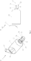
- an inhalation chamber (2) such as pictured in Figs. 1 and 2 .
- This device consists of a closed inhalation chamber (2) connected to the MDI (1).
- a second end (3), commonly a mouthpiece is attached to the other end of the inhalation chamber (2) and contains a flexible inhalation valve (4) which opens when the patient inhales and closes when he/she expires.
- the inhalation chamber (2) plays the role of drug reservoir which empties when the patient inhales.
- the velocities of the drug substance particles are reduced at the mouth and therefore the losses of drug substance by impaction are reduced in the upper respiratory tract.
- this device allows a better deposition of the drug substance in the targeted zone of action of the drug (the alveolar zone) compared to a single metered dose inhaler.
- the patent US 2013/0008436 discloses a respiraoty drug delivery apparatus including sensors for detecting to sens parameter relating to the use of the apparatus. For example, the presence of particles is detected by light sensors. However, the location of the measurement is not suitable.
- An inhalation apparatus comprising an inhalation chamber and a flow measuring apparatus for measuring a flow of particles from the inhalation chamber, the inhalation chamber having a first end to be connected to the source of drug, such as a metered drug inhaler, to be administered by inhalation do a user, and a second end to be connected to the user, through a section of an inhalation apparatus, said section being located between the second end of the inhalation chamber and the user, the flow measuring apparatus being located in the section of the inhalation apparatus and comprising:
- the flow measuring apparatus of the present invention may comprise:
- the flow measuring apparatus of the present invention may comprise at least a first and a second sensor, the first sensor configured to measure the flow of particles along a first axis, and the second sensor configured to measure the flow of particles along a second axis perpendicular to the first axis.
- the flow measuring apparatus may further comprise a processor operatively connected to the sensor for processing a measured disturbance of the electromagnetic radiation.
- the processor may be operatively connected to the sensor for controlling one or more of a wavelength, a frequency, or an intensity of the electromagnetic radiation emitted by the light source.
- the light source emits at wavelength from about 400 nm to about 1 mm.
- the light source emits at wavelength from about 450 nm to about 600 nm.
- One of the photo-detection device has a light source emitting at wavelength from ⁇ 600 nm and another photo-detection device has a light source emitting at wavelength >600 nm.
- the flow measuring apparatus may further comprise a visual means, operatively connected to the processor, for providing information about the flow of particles.
- the visual means may be an indicator light, a display means, or combinations thereof.
- the flow measuring apparatus may further comprise a transmission means, operatively connected to the processor, for transmitting information about the flow of particles to an external device.
- the processor may be operative to provide a rate of drug delivery.
- the visual means may be mounted on the flow measuring apparatus.
- the visual means and the processor are configured to provide additional information regarding use of the flow measuring apparatus.
- the visual means may be a detachable display.
- the display means may be a plate comprising a visual information, an illuminated plate comprising a visual information, an LCD display, or a combination thereof.
- the detachable display may be configured to be attached to a separate base.
- the separate base may be a powered base, to power the detachable display.
- the detachable base further comprise any one of a processor, memory, storage, input interface, and output interface.
- the base may be integral to the detachable display.
- an inhalation apparatus for drug delivery by inhalation comprising:
- the inhalation apparatus may further comprise an expiration conduit downstream of the second end, for exit of air expired by the user.
- the expiration conduit may further comprise an expiration sensor comprising a photo-detection device comprising a light source and a detector, wherein the light source may be configured to emit electromagnetic radiation of wavelength > 600 nm onto the detector along a light path, wherein the detector may be configured to measure disturbance of the electromagnetic radiation by mist formation from the expired air from the user.
- an expiration sensor comprising a photo-detection device comprising a light source and a detector, wherein the light source may be configured to emit electromagnetic radiation of wavelength > 600 nm onto the detector along a light path, wherein the detector may be configured to measure disturbance of the electromagnetic radiation by mist formation from the expired air from the user.
- the inhalation apparatus may further comprise an upstream sensor, upstream of the valve, and comprising a photo-detection device comprising an upstream light source and an upstream detector, wherein the upstream light source may be configured to emit electromagnetic radiation of wavelength >600 nm onto the detector along a light path, wherein the upstream detector may be configured to measure disturbance of the electromagnetic radiation by the flow of particles to provide measurements of the presence and mass of particles within an upstream section of the inhalation apparatus.
- an inhalation apparatus for the administration of a drug by inhalation to a subject in need thereof, comprising administering the drug with an inhalation apparatus according to the present invention.
- the method may further comprise the step of measuring a disturbance of an electromagnetic radiation emitted from the sensor caused formation of a mist or a fog caused by exhalation of the user in the inhalation apparatus.
- the method may further comprise the step of synchronizing administration of the drug with a decrease of the disturbance of an electromagnetic radiation emitted from the sensor caused by inhalation of the subject in the inhalation apparatus.
- the method may further comprise the step of measuring a flow of particles.
- the measuring includes at least one of measuring the presence of the flow of particles, measuring the mass of the flow of particles, measuring the velocity of the flow of particles, or combinations thereof.
- the method may further comprise the step of generating a notification in view of the measuring a flow of particles.
- the notification may be audible, visible, or both.
- the velocity of the flow of particles may be at or above a threshold rate, the notification may be representative of a successful administration.
- the velocity of the flow of particles may be below a threshold rate, the notification may be representative of an unsuccessful administration.
- an inhalation apparatus for the administration of a drug by inhalation to a subject in need thereof.
- an inhalation apparatus for the administration of a drug by inhalation to a subject in need thereof.
- light source is intended to mean any suitable source of electromagnetic radiation which may be detected by an attendant detector.
- suitable sources of lights may be light emitting diodes (LED) or a laser diode, emitting electromagnetic radiation which will be detected by the opposed detector (14).
- the wavelength of the electromagnetic radiation used may be any suitable wavelength, for example from about 100 nm to about 1 mm, or from about 400 nm to about 1 mm, or from about 500 nm to about 1 mm, or from about 600 nm to about 1 mm, or from about 700 nm to about 1 mm, or from about 800 nm to about 1 mm, or from about 900 nm to about 1 mm, or from about 1 ⁇ m to about 1 mm, or from about 10 ⁇ m to about 1 mm, or from about 100 ⁇ m to about 1 mm, or from about 200 ⁇ m to about 1 mm, or from about 300 ⁇ m to about 1 mm, or from about 400 ⁇ m to about 1 mm, or from about 500 ⁇ m to about 1 mm, or from about 600 ⁇ m to about 1 mm, or from about 700 ⁇ m to about 1 mm, or from about 800 ⁇ m to about 1 mm, or from about 900 ⁇ m to about 1 mm, from about 100
- detector is intended to mean photo-sensors or photodetectors which are sensors of light or other electromagnetic energy, which measure the electromagnetic radiation emitted by the light source. Suitable detectors include but are not limited to photo-resistors, photodiodes, or phototransistors.
- Fluid is intended to mean a substance that continually deforms (flows) under an applied shear stress. Fluids are a subset of the phases of matter and include liquids, gases, plasmas and, to some extent, plastic solids. Fluids can be defined as substances that have zero shear modulus or in simpler terms a fluid is a substance which cannot resist any shear force applied to it. According to embodiments, preferred fluids are liquids and gases, more preferably gases, and especially gasses having particles of medication or drugs suspended therein. According to an embodiment, the gas may be gaseous discharge containing dry powder of a medicamentous substance found in a metered dose inhaler for example.
- photo-detection device is intended to mean a device comprising a light source and a detector to measure the electromagnetic radiation emitted by the light source.
- inhalation apparatus is intended to mean a medical device used for delivering medication into the body via the lungs. This includes metered-dose inhalers, dry powder inhalers, nebulizers and nasal inhalers, for example.
- masses or “measured mass” or “total mass” is intended to mean the quantity, amount, of particles of the drug particles that flowed through the section of the fluid dispensing apparatus.
- the measurement of the mass of drug particle allows the determination of the actual dose inhaled by the subject, and allows determining if the subject is getting an adequate or inadequate treatment.
- a flow measuring apparatus (5) for measuring a flow of particles through a section of a fluid dispensing apparatus.
- a flow measuring apparatus for measuring a flow of particles through a section of a fluid dispensing apparatus which comprises a sensor which comprises at least one photo-detection device comprising a light source (12) and a detector (14), where the light source (12) is configured to emit electromagnetic radiation onto the detector (14) along a light path and the detector (14) is configured to measure disturbance of the electromagnetic radiation by the flow of particles to provide a measurement of the presence of particles within the section of the fluid dispensing apparatus and a measurement of a mass of the particles flowing in the section of a fluid dispensing apparatus.
- the detection of the presence of particles allows a more accurate counting of the number of doses administered, since some drug delivery devices (e.g. MDI) when not handled properly, only eject propellant gas without any drug particles. Furthermore, the detection of the mass or amount of drug particles administered allows the determination of an adequate or inadequate amount of drug particles has been delivered for the desired treatment.
- drug delivery devices e.g. MDI
- the apparatus (5) comprises a sensor, which comprises at least two photo-detection devices.
- Each photo-detection device comprises a light source (12) and a detector (14).
- the light source (12) is configured to emit electromagnetic radiation onto the detector (14) along a light path (16), and the detector (14) is configured to measure disturbance of the electromagnetic radiation by the flow of particles flowing through the light path.
- the light paths (16) between each light source (12) and detector (14) pair are parallel to one another, and at least one of the light paths is inverted with respect to the other light paths.
- the sensor comprising at least two photo-detection devices allows the detection of the presence of particles, their total mass, and the velocity of the particles.
- the flow measuring apparatus (5) for measuring a flow of particles through a section of a fluid dispensing apparatus may comprise at least a first sensor, configured to measure the flow of particles along a first axis, and a second sensor, configured to measure the flow of particles along a second axis perpendicular to the first axis.
- each sensor comprises at least one or at least two photo-detection devices.
- Each photo-detection device comprises a light source (12) and a detector (14).
- the light source (12) is configured to emit electromagnetic radiation onto the detector (14) along a light path (16), and the detector (14) is configured to measure disturbance of the electromagnetic radiation by the flow of particles.
- the light paths (16) between each light source (12) and detector (14) pair are parallel to one another, and at least one of the light paths is inverted with respect to the other light paths.
- the photo-detection device may comprise a light source (12) which may be for example a light emitting diode (LED) or a laser diode, emitting electromagnetic radiation which will be detected by an opposed detector (14) such as a photo-resistor, a photodiode, or a phototransistor, as shown schematically in Fig. 3A .
- the wavelength of the electromagnetic radiation used may be between any suitable wavelength, and for example the wavelength described above, particularly at about 200 nm to 1 mm, or about 400 nm to 1 mm (which includes the visible spectrum up to the far infrared), according to the suspension or the drug used.
- the infrared spectrum may be preferred, while according to other examples, visible light may be used.
- the wavelength of light may be from a range including more than one specific type of light (e.g. visible, infrared and ultraviolet).
- these medicaments may be transported by droplets of propulsion gas that are capable to mostly or entirely absorb the infrared light. Limiting detection to this spectrum detects the droplets of propulsion gas, but does not detect the active pharmaceutical ingredient. Therefore, the use of visible light for example, instead of, or in combination with infrared light allows detection of the active pharmaceutical ingredient.
- the photo-detector devices are placed on either side of the path of the flow of particles. This jet will disturb the electromagnetic radiation, and measurement and analysis of this disturbance will allow the determination of the amount of inhaled drug particles. Indeed, the passage of suspended particulates will cause a change in the intensity of the optical signal received by the detector, which will then emit a different amplitude electrical signal.
- the apparatus of the present invention are non-invasive, that is to say that there is no contact between the apparatus and aerosols, so that it will not disturb the flow of particles.
- the flow measuring apparatus (5) may be used to measure flow, including the presence, mass (i.e. amount) and velocity of particles having different shapes and configurations.
- the flow of particle may be a homogenous distribution of particles flowing through an enclosure (such as a tubular enclosure, or a relatively tubular enclosure).
- the flow of particle may exit from a valve which leaves the flow homogenously distributed, or relatively so.
- the flow of particle may be a jet of particles flowing through an enclosure.
- the jet may be any type of jet, for example a narrow jet and uniform jet, a wide and uniform jet, or a jet having a shape imparted by an upstream element, such as a valve having an opening that may shape the flow of particle as in passes therethrough.
- the flow of particle may be a relatively flat jet, for example at the exit of a duckbill valve (4) where the flow of aerosol particles forms a relatively flat jet.
- the flow of particles is relatively homogenously distributed within the enclosure, no particular configuration of the photo-detection device may be necessary, as the emitted electromagnetic radiation will interact with particles in approximately the same manner irrespective of the provenance of electromagnetic radiation.
- the flow of particles may be non-homogenously distributed within the enclosure, such as for the relatively flat jet described above, two configurations may be retained to make appropriate measurements, as illustrated in Fig. 3B : configuration 1 where the optical path (16) is in the plane of the jet, and configuration 2 where the optical path is perpendicular to the plane of the jet.
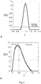
- Both configurations yield different and complementary velocimetric information.
- the correlation between the two signals thus collected allows the determination of velocimetric information and throughput. This information may be obtained by cross-correlation of optical signals.
- the particle velocity at the outlet of the second end (3) and/or flexible inhalation valve (4) is not uniform. Indeed, it is fast in the center of the jet and slower at the edges.
- Flow measuring apparatus configured according to configuration 1 will determine an average velocity in the plane of the jet or flow (F), while those configured according to configuration 2 will give information on the velocity profile in the center of the jet.
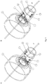
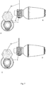
- Figs. 4A and 4B show the position of two photo-detection device in the two configurations. To limit stray flux received by the detectors, the optical paths (16) of each photo-detection device will be opposite, as shown in Figs. 5A and 5B .
- the photo-detection devices may be operatively connected to a processor (and/or controller) (30).
- the processor 30 may be both a processor and a controller, or a processor only, wit a separate device taking in charge any of the controllable features of the present apparatus.
- controller and processor are to be used interchangeably to identify a means of controlling aspects of the present invention in need of being controlled, and means of processing the harnessed information concerning the disturbances in the electromagnetic radiation measured by the detector (14).
- the processor (30) is operatively connected to the sensor(s) of the flow measuring apparatus (5) for calculating the flows from the disturbances in the electromagnetic radiation measured by the detector.
- the processor (30) may also be operatively coupled to the flow measuring apparatus (5) for controlling the wavelength of the electromagnetic radiation emitted by the light source (12), as well as frequency and intensity.
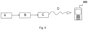
- the processor (30) may transmit a flow rate signal and/or activate visual means, such as a light emitting diode, or a display means indicating information concerning the measured flow, including the presence, mass (i.e. amount) and velocity of particles therein. The operation of these elements is described in Fig. 6 .
- an inhalation apparatus for drug delivery by inhalation.
- This inhalation apparatus comprises an inhalation chamber (2) having a first end (20) to be connected to a source of drug [such as MDI (1)] to be administered by inhalation to a user, and a second end (3) to be connected to the user.
- a valve (4) is disposed upstream of the inhalation chamber (2) and downstream of the second end (3), allowing passage of a flow of drug particles from the inhalation chamber (2) to the second end (3), and a flow measuring apparatus (5) of the present invention, as described above, upstream of the valve (4), for measuring flow, including the presence, mass (i.e. amount) and velocity of drug particles.
- the valve (4) may be any suitable valve that may be selected from and not limited to the wide selection of valve already known in the art, such as diaphragm valves, and duckbill valves.
- the photo-detection devices of the flow measuring apparatus (5) may be operatively connected to a processor (30).
- the processor (30) may be operatively connected to a sensor of the flow measuring apparatus (5) for calculating the flows from the disturbances in the electromagnetic radiation measured by the detector.
- the processor (30) may also be operatively coupled to the sensor of the flow measuring apparatus (5) for controlling the wavelength of the electromagnetic radiation emitted by the light source (12), as well as frequency and intensity.
- the processor (30) may transmit a flow rate signal and/or activate audible and/or visual means, such as speakers, an indicator light (e.g.light emitting diode), or a display means indicating information concerning the measured flow and/or information about the proper use of the inhalation apparatus. The operation of these elements is described in Fig. 6 .
- the flow measuring apparatus (5) measures disturbance of the electromagnetic radiation by the flow of particles (step A).
- the processor (30) receives the optical signal received by the detector and calculates the flow rate (step B).
- the transmission means (32) transmits the signal flow delivered by the processor (30) to an external device 400, such as a portable machine equipped with a Bluetooth system or the likes (step D).
- an external device 400 such as a portable machine equipped with a Bluetooth system or the likes
- This can be for example a cell phone, a tablet, etc.
- This allows the display on the external device (400) of either the flow value measured, or an indication to the user that a correct rate value and a proper functioning, or an incorrect rate value and an improper functioning of the inhalation apparatus (200).
- a signal for the rate of drug delivery from the processor (30) to a visual means attached to the inhalation apparatus (10) (step C) of Fig. 6 and/or to the flow measuring apparatus (5).
- the visual means may be for example a LED which illuminates when the value of the measured flow is the expected value or when on the contrary the value of the measured flow rate is less than a predetermined threshold value. This informs the user of the good or improper use or operation of the inhalation apparatus (10) and the smooth running of the treatment.
- the processor (30) may transmit a signal corresponding to the rate of drug delivery to a visual means which may comprise an indicator light (e.g. a LED) (40), operatively coupled to a display (42).
- a visual means which may comprise an indicator light (e.g. a LED) (40), operatively coupled to a display (42).
- the indicator light (40) and display (42) may be mounted upon the flow measuring apparatus (5).
- the display (42) may be mounted through known means such as insertion in a slot, or any other suitable means.
- the display (42) may be a Plexiglas® plate, or an equivalent material.
- the plate may be etched or engraved with visual information upon which the light of the indicator light (40) may be reflected.
- the color and intensity of the light reflected upon the display (42) may be varied such that information concerning the flow measured by the flow measuring apparatus (5) may be communicated to the user.
- the indicator light (40) could display an assortment of lights on the display (42) designed at getting the user's attention when the flow measuring apparatus (5) is correctly or incorrectly used.
- the indicator light (40) could display an assortment of lights on the display (42), thus illuminating the informative and/or amusing engraved visual information designed at getting the user's attention when the flow measuring apparatus (5) is correctly or incorrectly used.
- the display (42) may also be used to display other information not related directly to the flow information measured, such as the status of an energy source electrically coupled to the apparatus (5), the number of doses administered and/or remaining in the source or drug coupled to the apparatus, etc., or any other information stored on attendant memory or storage means.
- the processor (30) of a flow measuring apparatus (5) may transmit a signal corresponding to the rate of drug delivery to a visual means such as a display (42).
- a visual means such as a display (42).
- the display (42) may be mounted upon the flow measuring apparatus (5), through known means such as insertion in a slot, or any other suitable means.
- the display (42) may be a liquid crystal display (LCD) or an equivalent device.
- the LCD may be used to display visual information obtained from the processor (30), corresponding to the status of the flow measuring apparatus, and/or other information stored on attendant memory or storage means.
- visual information upon the display (42) may be varied such that information concerning the flow measured by the flow measuring apparatus (5) may be communicated to the user.
- the visual information displayed upon the display (42) may be designed at getting the user's attention when the flow measuring apparatus (5) is correctly or incorrectly used.
- the display (42) may also be used to display other information not related directly to the flow information measured, such as the status of an energy source electrically coupled to the apparatus (5), the number of doses administered and/or remaining in the source or drug coupled to the apparatus, etc., or any other information stored on attendant memory or storage means.
- the display (42) may be a detachable display.
- the detachable display may be interchanged with another display. This detachable display may be advantageous feature to replace broken or damaged displays.
- the apparatus of the present invention may be provided with alternative displays (42), or such additional alternative displays (42) could be purchased separately, to be used with the flow measuring apparatus (5) of the present invention.
- the display (42) may be plates etched or engraved with differing visual information (e.g. different artistic images, different language information, and the likes) upon which a light source may be reflected.
- detachable display (42) may be a liquid crystal display (LCD) or an equivalent device, as described above.
- LCD liquid crystal display
- the LCD displays may be of various size and density, so as to suit a number of applications as may be necessary.
- the LCD display may be of a relatively low quality to meet a specific price point, or it may be of a high quality and/or durability, so as to be used under professional conditions where the flow measuring apparatus (5) of the present invention could be used frequently by several distinct users.
- the detachable display (42) may be mounted (fastened) to the flow measuring apparatus (5) through conventional market methods of attaching two objects in a detachable manner.
- the detachable display (42) may be separated from separated from the flow measuring apparatus (5) when a certain pulling, twisting, pushing, or other force is applied to the the display (42) without any tools needed. This solves the problem that a user may apply too much torque to the flow measuring apparatus (5) when pulling out the detachable display (42) and as a result break the flow measuring apparatus (5).
- the detachable display (42) may be separated from separated from the flow measuring apparatus (5) when a certain pulling, twisting, pushing, or other force is applied to the the display (42), with an appropriate tool, and/or after fasteners holding the display (42) have been previously been detached with appropriate tools. This solves the problem that a user may inadvertently detach the display (42) when applying too much torque to the flow measuring apparatus (5).
- the detachable display (42) may be reattached to a separate base (50).
- the base (50) may be a simple base on which the unused display (42) may be placed to present the artwork found on the display (42).
- the base (50) may be a powered base, comprising the necessary electrical means to power (e.g. externally or internally - wired or battery powered) and/or illuminate the display (42) attached thereto.
- the base (50) may comprise the necessary electrical circuits to power one or more LED lights to illuminate the attached display (42), which could cycle through different colors and intensities.
- the base (50) and display (42) may be used as a night light for a young child, which would associate the images displayed in the night light, along with some addible signals, with a positive use of the flow measuring apparatus (5) of the present invention.
- the base (50) may comprise processor, memory, storage, output (e.g. speakers, lights, other displays) and interfacing (e.g. USB ports, Wi-Fi, and Bluetooth®) means, as well as the necessary electrical means to power an LCD based display (42) so as to store information onto the base (50) for display on the display (42).
- the LCD based display could display pictures, videos, or information in succession, provide a visual and/or audio reminder or alarm at a predetermined time interval, etc., for use as a night light, information and entertainment device.
- the base (50) may be a powered base, comprising the necessary electrical means to power and/or illuminate the display (42) attached thereto.
- the base (50) may comprise the necessary electrical circuits to power an attached display (42) and the attached display (42) may comprise an assortment of processor, memory, storage, output (e.g. speakers, other displays) and/or interfacing (e.g. USB, Wi-Fi, and Bluetooth®) means, to be powered by the electrical means in the base (50).
- the information stored onto the storage of the display (42) could be displayed onto the display.
- the LCD based display could display pictures, videos, or information in succession, provide a visual and/or audio reminder or alarm at a predetermined time interval, etc.
- the base (50) may be integral (built in or built with) the display (42).
- display (42) may comprise a flat surface or legs underneath it which may act as a base (50).
- the display (42) may comprise an assortment of processor, memory, storage, output (e.g. speakers, other displays) and/or interfacing (e.g. USB, Wi-Fi, and Bluetooth®) means, and electrical means required to power it to illuminate the artwork on the display (42) and/or the LCD based display.
- the information stored onto the storage of the display (42) could be displayed onto the display.
- the LCD based display could display pictures, videos, or information in succession, provide a visual and/or audio reminder or alarm at a predetermined time interval, etc.
- the combined base (50) and display (42) may also comprise the necessary electronic means (e.g. a timer or clock function) to provide a visual and/or audio reminder or alarm at a predetermined time interval.
- the interfacing means present in the display (42) and/or base (50) may also be used to communicate the collected information concerning the flow information measured, the status of an energy source electrically coupled to the apparatus (5), the number of doses administered and/or remaining in the source or drug coupled to the apparatus, etc., or any other information stored on attendant memory or storage means, to an external application.
- the flow information measured, the number of doses administered and/or remaining in the source or drug coupled to the apparatus could be provided to a treating physician to monitor progress of the treatment.
- Other information stored on the apparatus (5) and/or on the base (50) could potentially be used for remote diagnostic of a failing apparatus (5), for example.
- a method for the administration of a drug by inhalation to a subject in need thereof which comprises administering the drug with an inhalation apparatus according to the present invention.
- the method may further comprise the step of measuring a disturbance of the electromagetic radiation emitted from the sensor which may be caused when the subject using the apparatus exhales (expires) therein. Indeed, the exhalation of warm air from the lungs of the subject causes the formation of mist inside the inhalation apparatus, which may be detected by the sensor of the present invention.
- Using a photo-detection device having a light source having wavelength >600 nm with an inhalation chamber allows the detection of the inspirations and expirations of the patient. This has the advantage of allowing the user to know when to actuate the inhaler, the best time being during inspiration.
- the fog detection with light >600 nm can be restrictive as the mist created in the mouthpiece can be confused with a passage of an aerosol.
- the use of at least two photo-detection device, at least one of which has light source having a wavelength >600 nm eliminates this problem for the detection of aerosols and allow detection of the patient's breathing.
- the possible configurations to ensure these two functions are as follows:
- a first photo-detection device having a light source of wavelength ⁇ 600 nm is used for measurements for aerosols
- a second photo-detection device having a light path of wavelength >600 nm is used for fog detection.
- the configuration of the two optical paths may be that of Fig. 4 .
- the photo-detection devices are placed after the valve. The sensor as follows: During the passage of aerosols, the two signals reach their limit of detection. When the fog is produced into the mouthpiece, only the second photo-detection device having light source of wavelength >600 nm reaches the detection threshold.
- photo-detection device having a light source of wavelength ⁇ 600 nm and photo-detection device having a light source of wavelength of wavelength >600 nm version 2
- a second possibility is to place an additional photo-detection device having a light source of >600 nm in an expiration conduct of the inhalation apparatus or any other conduct that is affected by the fog created during exhalation but where there is no passage of aerosols. According to this embodiment, only the mist is detected there.
- the other photo-detection device(s) having a light source of wavelength ⁇ 600 nm is/are placed after the valve.
- the sensor then works as follows: During the passage of aerosols, the one or more from the photo-detection device(s) having a light source of wavelength ⁇ 600 nm signals reach their limit of detection. When the fog is produced into the mouthpiece, the single photo-detection device having light source of wavelength >600 nm in the exhalation pipe reaches the detection threshold
- a first sensor with photo-detection device having light source of wavelength > 600 nm is placed in a space which is not reached by the fog but where aerosols flows, for example upstream of the valve 4 of Fig. 1 .
- the signal of this photo-detection device only detects the presence of aerosol.
- the other second sensor(s) may be placed at the valve outlet to perform the functions for measuring the flow of aerosols and mist detection.
- the sensors then work as follows: when the fog is produced into the mouthpiece, the signals from the first and second sensors reach the detection threshold, and when the fog is produced into the mouthpiece only the photo-detection device at the valve outlet will reach the threshold of detection.
- the one photo-detection device having a light source of wavelength > 600 nm when only one photo-detection device having a light source of wavelength > 600 nm is used, it is placed in an expiration conduit of the inhalation apparatus or any other conduct that is affected by the fog created during exhalation but where there is no passage of aerosols. According to this embodiment, only the mist is detected there.
- the one or more from the photo-detection device(s) having a light source of wavelength ⁇ 600 nm near the output valve reach their limit of detection threshold.
- the two photo-detection device reach their detection threshold
- the apparatus is configured to perform a step where the administration of the drug is synchronized (or coordinated) based on the detection of this exhaled mist and/or by measurement of a decrease in the disturbance of the electromagnetic radiation emitted from the sensor caused by inspiration of the subject in the inhalation apparatus, and the corresponding disappearance of this mist formed during exhalation.
- the display means or audible means of the flow measuring apparatus may also be used to provide instructions to the user, for example, to instruct the use to start inhaling or exhaling, to initiate a coordinated and adequate administration of the drug.
- the method may further comprise the step of measuring a flow of particles.
- the detection of the flow of aerosol is measured when the signal value exceeds a threshold rate that depends on the medication administered.
- an audible or visual notification informs the patient that he has inhaled the aerosol drug. That is to say, when a velocity of the flow of particles is at or above a threshold rate, the notification is representative of a successful administration; and when a velocity of the flow of particles is below a threshold rate, the notification is representative of an unsuccessful administration.
- the respiratory cycle of inspiration/expiration is detected with the sensor of the present invention, and is used to time (coordinate, synchronize) the administration of the drug substance of interest.
- This coordination may be combined with an audible and/or visual signal providing instructions to the user regarding the appropriate action to take to perform the administration.
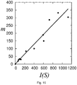
- the aerosol mass is correlated to the time integral of the signal.
- the empirical relationship between mass and the time integral of the signal is obtained from the mass measurement (e.g. measurement on filters or with a cascade impactor) in the laboratory.
- An example of a calibration curve of the mass as a function of the integral of S (t) signal for a corticosteroid (Fluticasone 50 mcg per dose) is shown in Fig. 10 .
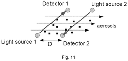
- Photo-detection devices are assembled from infrared emitters (light sources 1 and 2), and photodiodes (detectors 1 and 2).
- the detectors are operatively coupled to signal filters to eliminate undesired signal frequencies (e.g. a RC high-pass filter at about 3 Hz to eliminate the DC component, and a Butterworth 3 to 10 Hz low-pass filter), and also operatively coupled to an operational amplifier (e.g. MCP602, from MicrochipTM), mounted to provide a non-inverted gain of 210.
- an operational amplifier e.g. MCP602, from MicrochipTM
- Operatively coupled to these component is a controller, for example a micro-controller PIC10LF320 from MicrochipTM.
- the two photo-detection devices are arranged in the plane formed by the aerosol jet, perpendicularly to the direction of flow.
- the light source 1 is arranged on the same side as the detector 2, and the light source 1 is arranged on the same side as detector 1, so that the detectors only receive radiation from their matched light source ( Fig. 11 ).
- the axes of the light beams (photons) are parallel and separated by a distance D determined with high accuracy.
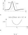
- the temporal signals measured by each detector are recorded as S1(t) and S2(t), and have intensity as shown in Fig. 12A .
- Each signal displays a peak due to the passage of aerosols, each peak being time-shifted relative to the other.
- the determination of the time difference between the two signals S1(t) and S2(t) can be traced back to the speed of the aerosols. Shifting the signal S2(t) of a certain duration T brings the two signals in sync, and superimpose them, at least partially.
- the "error" E(T) is defined as the integral of (S1(t) - S2(t + T)) 2 ( Fig. 12B ).
- the signals may have to be centered or re-scaled to optimize the computation of the error. This integral is approximated by a simple discrete sum.
Landscapes
- Health & Medical Sciences (AREA)
- Engineering & Computer Science (AREA)
- Life Sciences & Earth Sciences (AREA)
- General Physics & Mathematics (AREA)
- Physics & Mathematics (AREA)
- Animal Behavior & Ethology (AREA)
- Public Health (AREA)
- Biomedical Technology (AREA)
- Heart & Thoracic Surgery (AREA)
- Hematology (AREA)
- Pulmonology (AREA)
- General Health & Medical Sciences (AREA)
- Anesthesiology (AREA)
- Veterinary Medicine (AREA)
- Bioinformatics & Cheminformatics (AREA)
- Fluid Mechanics (AREA)
- Biophysics (AREA)
- Multimedia (AREA)
- Aviation & Aerospace Engineering (AREA)
- Emergency Medicine (AREA)
- Infusion, Injection, And Reservoir Apparatuses (AREA)
Claims (15)
- Appareil d'inhalation (10) comprenant une chambre d'inhalation (2) et un appareil de mesure de débit (5) pour mesurer un flux de particules provenant d'une chambre d'inhalation, la chambre d'inhalation ayant une première extrémité (20) à relier à la source (1) de médicament, telle qu'un inhalateur de médicament dosé, à administrer par inhalation à un utilisateur, et une seconde extrémité (3) à relier à l'utilisateur, par l'intermédiaire d'une section de l'appareil d'inhalation, ladite section étant située entre la seconde extrémité de la chambre d'inhalation et l'utilisateur, l'appareil de mesure de débit étant situé dans la section de l'appareil d'inhalation et comprenant :• un capteur comprenant au moins un dispositif de photodétection, chacun des au moins un dispositif de photodétection comprenant une source de lumière (12) et un détecteur (14),ladite source de lumière étant configurée pour émettre un rayonnement électromagnétique sur ledit détecteur le long d'un trajet lumineux (16),
ledit détecteur étant configuré pour mesurer la perturbation dudit rayonnement électromagnétique par ledit flux de particules provenant de la chambre d'inhalation pour fournir des mesures de la présence de particules à l'intérieur de ladite section de l'appareil d'inhalation et des mesures d'une masse des particules s'écoulant à travers l'appareil d'inhalation. - Appareil d'inhalation selon la revendication 1, l'au moins un dispositif de photodétection comprenant au moins deux dispositifs de photodétection,
les trajets lumineux des au moins deux dispositifs de photodétection étant parallèles, et au moins un desdits trajets lumineux étant inversé par rapport à un autre des trajets lumineux. - Appareil d'inhalation selon l'une quelconque des revendications 1 et 2, ledit capteur étant configuré pour mesurer ledit flux de particules le long d'un premier axe, comprenant en outre un second capteur configuré pour mesurer ledit flux de particules le long d'un second axe perpendiculaire audit premier axe.
- Appareil d'inhalation selon l'une quelconque des revendications 2 et 3, comprenant en outre un processeur (30) relié de manière opérationnelle audit capteur pour traiter une perturbation mesurée dudit rayonnement électromagnétique ;
en option, ledit processeur étant opérationnel pour fournir un taux d'administration de médicament. - Appareil d'inhalation selon la revendication 4, ledit processeur étant relié de manière opérationnelle audit capteur pour commander une ou plusieurs d'une longueur d'onde, d'une fréquence ou d'une intensité du rayonnement électromagnétique émis par ladite source de lumière.
- Appareil d'inhalation selon l'une quelconque des revendications 1 à 5, ladite source de lumière émettant à une longueur d'onde de 400 nm à 1 mm, et de préférence de 450 nm à 600 nm.
- Appareil d'inhalation selon l'une quelconque des revendications 2 à 5, l'un desdits dispositifs de photodétection ayant une source de lumière émettant à une longueur d'onde < 600 nm et un autre dispositif de photodétection ayant une source de lumière émettant à une longueur d'onde > 600 nm.
- Appareil d'inhalation selon l'une quelconque des revendications 2 à 5, comprenant en outre un moyen visuel, relié de manière opérationnelle audit processeur, pour fournir des informations sur ledit flux de particules ;
en option, ledit moyen visuel étant monté sur ledit appareil de mesure de débit,
en option, ledit moyen visuel et ledit processeur étant configurés pour fournir des informations supplémentaires concernant l'utilisation dudit appareil de mesure de débit. - Appareil d'inhalation selon la revendication 8, ledit moyen visuel étant un témoin lumineux (40), un moyen d'affichage, un affichage détachable (42), ou des combinaisons de ceux-ci.
- Appareil d'inhalation selon l'une quelconque des revendications 4 à 9, comprenant en outre un moyen de transmission (32), relié de manière opérationnelle audit processeur, pour transmettre des informations concernant ledit flux de particules à un dispositif externe (400).
- Appareil d'inhalation selon l'une quelconque des revendications 9 et 10, ledit moyen d'affichage étant une plaque comprenant des informations visuelles, une plaque éclairée comprenant des informations visuelles, un écran LCD, ou une combinaison de ceux-ci.
- Appareil d'inhalation selon la revendication 11, ledit affichage détachable étant configuré pour être fixé à une base séparée (50),
en option, ladite base séparée étant une base alimentée, pour alimenter ledit affichage détachable,
en option, ladite base faisant partie intégrante dudit affichage détachable. - Appareil d'inhalation selon la revendication 12, ladite base détachable comprenant en outre l'un quelconque d'un processeur, d'une mémoire, d'un stockage, d'une interface d'entrée et d'une interface de sortie.
- Appareil d'inhalation selon la revendication 4, ledit processeur étant configuré pour détecter des changements dans la perturbation mesurée dudit rayonnement électromagnétique pour déterminer une occurrence d'inhalation ou d'expiration.
- Appareil d'inhalation selon la revendication 14, ledit processeur étant en outre configuré pour synchroniser une administration d'un médicament sur la base des changements détectés.
Applications Claiming Priority (4)
| Application Number | Priority Date | Filing Date | Title |
|---|---|---|---|
| US201562149019P | 2015-04-17 | 2015-04-17 | |
| US201562166225P | 2015-05-26 | 2015-05-26 | |
| US201562233524P | 2015-09-28 | 2015-09-28 | |
| PCT/CA2016/050446 WO2016165029A1 (fr) | 2015-04-17 | 2016-04-18 | Appareil de mesure optique du débit et appareil d'inhalation le comprenant |
Publications (3)
| Publication Number | Publication Date |
|---|---|
| EP3283855A1 EP3283855A1 (fr) | 2018-02-21 |
| EP3283855A4 EP3283855A4 (fr) | 2018-10-03 |
| EP3283855B1 true EP3283855B1 (fr) | 2021-06-23 |
Family
ID=57125634
Family Applications (1)
| Application Number | Title | Priority Date | Filing Date |
|---|---|---|---|
| EP16779378.5A Active EP3283855B1 (fr) | 2015-04-17 | 2016-04-18 | Appareil d'inhalation comprenant une chambre d'inhalation et un appareil de mesure optique du débit |
Country Status (4)
| Country | Link |
|---|---|
| US (1) | US20180126099A1 (fr) |
| EP (1) | EP3283855B1 (fr) |
| CA (1) | CA2982987C (fr) |
| WO (1) | WO2016165029A1 (fr) |
Families Citing this family (19)
| Publication number | Priority date | Publication date | Assignee | Title |
|---|---|---|---|---|
| TWM506609U (zh) * | 2015-05-27 | 2015-08-11 | Ind Tech Res Inst | 呼吸器之藥量監控裝置 |
| JP7155010B2 (ja) | 2016-03-24 | 2022-10-18 | トゥルーデル メディカル インターナショナル | 電子インジケータを備えた呼吸治療システム |
| MX2018014121A (es) | 2016-05-19 | 2019-04-29 | Trudell Medical Int | Camara de retencion con valvula inteligente. |
| US20180004393A1 (en) * | 2016-07-01 | 2018-01-04 | Autodesk, Inc. | Three dimensional visual programming interface for a network of devices |
| ES2988939T3 (es) | 2016-07-08 | 2024-11-22 | Trudell Medical Int Inc | Dispositivo de presión espiratoria positiva oscilante inteligente |
| DE202017007545U1 (de) | 2016-12-09 | 2022-09-01 | Trudell Medical International | Intelligenter Vernebler |
| EP4585247A3 (fr) | 2018-01-04 | 2025-07-23 | Trudell Medical International Inc. | Dispositif intelligent à pression expiratoire positive oscillante |
| EP4734125A3 (fr) | 2018-06-04 | 2026-06-03 | Trudell Medical International Inc. | Chambre de maintien à valve intelligente |
| JP7389063B2 (ja) * | 2018-07-04 | 2023-11-29 | フラウンホファー ゲセルシャフト ツール フェールデルンク ダー アンゲヴァンテン フォルシュンク エー.ファオ. | エアロゾル送達を判定するデバイスおよび方法 |
| US20220168518A1 (en) * | 2019-02-27 | 2022-06-02 | NuvoAir AB | A method and a device for estimating an amount of a powder shaped material passing a bend in a flow channel |
| WO2020225663A1 (fr) * | 2019-05-07 | 2020-11-12 | 3M Innovative Properties Company | Inhalateur et méthode de détection d'obstruction |
| JP2022532542A (ja) * | 2019-05-07 | 2022-07-15 | キンデーバ ドラッグ デリバリー リミティド パートナーシップ | システム、吸入器及び監視方法 |
| ES2807698B2 (es) * | 2019-08-23 | 2022-01-03 | Igncyerto S L | Dispositivo y metodo de medicion de dosis en inhaladores de polvo seco |
| WO2021038467A1 (fr) | 2019-08-27 | 2021-03-04 | Trudell Medical International | Dispositif intelligent à pression expiratoire positive oscillante |
| CN112526163A (zh) * | 2019-09-30 | 2021-03-19 | 无锡三捷医疗科技有限公司 | 吸入气流流速检测装置、系统以及方法 |
| CN114787820A (zh) | 2019-12-10 | 2022-07-22 | 鲁德尔国际医疗公司 | 集成式剂量计数器 |
| US11464923B2 (en) | 2020-06-19 | 2022-10-11 | Norton (Waterford) Limited | Inhaler system |
| US12274545B2 (en) * | 2022-04-28 | 2025-04-15 | Gmeci, Llc | Methods and systems for detection of atelectasis in flight |
| CN115569274A (zh) * | 2022-11-03 | 2023-01-06 | 珠海格力电器股份有限公司 | 雾化器及其控制方法、装置和存储介质 |
Citations (1)
| Publication number | Priority date | Publication date | Assignee | Title |
|---|---|---|---|---|
| US20130008436A1 (en) * | 2010-01-07 | 2013-01-10 | Koninklijke Philips Electronics, N.V. | Respiratory drug delivery apparatus including a feedback and compliance device |
Family Cites Families (17)
| Publication number | Priority date | Publication date | Assignee | Title |
|---|---|---|---|---|
| DE4412494C2 (de) * | 1994-04-12 | 1997-02-27 | Kugelstrahlzentrum Aachen Gmbh | Verfahren zur Messung der Geschwindigkeitsverteilung eines Strahlmittelstromes |
| GB0026646D0 (en) * | 2000-10-31 | 2000-12-13 | Glaxo Group Ltd | Medicament dispenser |
| US6794671B2 (en) * | 2002-07-17 | 2004-09-21 | Particle Sizing Systems, Inc. | Sensors and methods for high-sensitivity optical particle counting and sizing |
| GB0405596D0 (en) * | 2004-03-12 | 2004-04-21 | Imi Vision Ltd | Fluid flow monitoring device |
| WO2006031775A2 (fr) * | 2004-09-13 | 2006-03-23 | Oriel Therapeutics, Inc. | Inhalateurs a poudre seche d'inhibition d'agregat, dispositifs et procedes associes |
| US20090103073A1 (en) * | 2005-03-23 | 2009-04-23 | Ohm Electric Co., Ltd. | Device and method for flow state observation |
| GB0518566D0 (en) * | 2005-09-12 | 2005-10-19 | Rosti As | A medicant dispenser, a device for monitoring dispensing of a medicant from a dispenser and a method of monitoring dispensation in such devices |
| GB0524911D0 (en) * | 2005-12-07 | 2006-01-11 | Univ Loughborough | Assessment of fine particle delivery |
| US8077294B1 (en) * | 2008-01-17 | 2011-12-13 | Ball Aerospace & Technologies Corp. | Optical autocovariance lidar |
| US8373858B2 (en) * | 2008-12-10 | 2013-02-12 | Livermore Instruments, Inc. | System and method for real time determination of size and chemical composition of aerosol particles |
| US9977045B2 (en) * | 2009-07-29 | 2018-05-22 | Michigan Aerospace Cororation | Atmospheric measurement system |
| US9285385B2 (en) * | 2010-08-09 | 2016-03-15 | Technical University Of Denmark | Vector velocimeter |
| CN104011562A (zh) * | 2011-11-29 | 2014-08-27 | 富丽达公司 | 运动稳定光探测和测距设备和用于本发明的风速测量领域的方法 |
| US9874580B2 (en) * | 2012-06-05 | 2018-01-23 | Newsouth Innovations Pty Limited | Method and system for determining a velocity of a relative movement between an object and a fluidal medium |
| US8964170B2 (en) * | 2012-12-10 | 2015-02-24 | The Johns Hopkins University | System and method for assessing the flow of a fluid |
| US9710917B2 (en) * | 2013-05-15 | 2017-07-18 | Massachusetts Institute Of Technology | Methods and apparatus for refractive flow measurement |
| US9851441B2 (en) * | 2014-01-27 | 2017-12-26 | University Corporation For Atmospheric Research | Method and system for generating a distance velocity azimuth display |
-
2016
- 2016-04-18 EP EP16779378.5A patent/EP3283855B1/fr active Active
- 2016-04-18 WO PCT/CA2016/050446 patent/WO2016165029A1/fr not_active Ceased
- 2016-04-18 US US15/567,004 patent/US20180126099A1/en not_active Abandoned
- 2016-04-18 CA CA2982987A patent/CA2982987C/fr active Active
Patent Citations (1)
| Publication number | Priority date | Publication date | Assignee | Title |
|---|---|---|---|---|
| US20130008436A1 (en) * | 2010-01-07 | 2013-01-10 | Koninklijke Philips Electronics, N.V. | Respiratory drug delivery apparatus including a feedback and compliance device |
Also Published As
| Publication number | Publication date |
|---|---|
| WO2016165029A1 (fr) | 2016-10-20 |
| US20180126099A1 (en) | 2018-05-10 |
| EP3283855A4 (fr) | 2018-10-03 |
| CA2982987C (fr) | 2018-05-29 |
| EP3283855A1 (fr) | 2018-02-21 |
| CA2982987A1 (fr) | 2016-10-20 |
Similar Documents
| Publication | Publication Date | Title |
|---|---|---|
| CA2982987C (fr) | Appareil de mesure optique du debit et appareil d'inhalation le comprenant | |
| US20230330362A1 (en) | Dry powder delivery device and methods of use | |
| ES2904623T3 (es) | Aparato interactivo para establecer un perfil en tiempo real de esfuerzos de inhalación | |
| US10046121B2 (en) | Inhalation device with feedback system | |
| CA2767019C (fr) | Nebuliseur pour nourrissons et patients atteints de problemes respiratoires | |
| US11273271B2 (en) | Aerosolization system with flow restrictor and feedback device | |
| CA2903965C (fr) | Nebuliseur pour nourrissons et patients atteints de problemes respiratoires | |
| JP2022508519A (ja) | 電子呼吸作動式エアロゾル吸入デバイスを介した肺系統への低表面張力組成物の送達 | |
| JPH10509062A (ja) | 投与量計測スペーサ | |
| AU2006227168A1 (en) | Methods and systems for operating an aerosol generator | |
| US20200023148A1 (en) | Optical dry powder inhaler dose sensor | |
| CN109475708B (zh) | 用于监测对吸入疗法的依从性的装置和方法 | |
| US20100242955A1 (en) | Aerosolized Drug Delivery System | |
| EP4146309B1 (fr) | Appareil et support de stockage non transitoire d'estimation d'une dose d'inhalation d'une personne | |
| HK1186996B (en) | An interactive apparatus for real-time profiling of inhalation efforts | |
| AU2013209385A1 (en) | Nebulizer for infants and respiratory compromised patients |
Legal Events
| Date | Code | Title | Description |
|---|---|---|---|
| STAA | Information on the status of an ep patent application or granted ep patent |
Free format text: STATUS: THE INTERNATIONAL PUBLICATION HAS BEEN MADE |
|
| PUAI | Public reference made under article 153(3) epc to a published international application that has entered the european phase |
Free format text: ORIGINAL CODE: 0009012 |
|
| STAA | Information on the status of an ep patent application or granted ep patent |
Free format text: STATUS: REQUEST FOR EXAMINATION WAS MADE |
|
| 17P | Request for examination filed |
Effective date: 20171116 |
|
| AK | Designated contracting states |
Kind code of ref document: A1 Designated state(s): AL AT BE BG CH CY CZ DE DK EE ES FI FR GB GR HR HU IE IS IT LI LT LU LV MC MK MT NL NO PL PT RO RS SE SI SK SM TR |
|
| AX | Request for extension of the european patent |
Extension state: BA ME |
|
| DAV | Request for validation of the european patent (deleted) | ||
| DAX | Request for extension of the european patent (deleted) | ||
| STAA | Information on the status of an ep patent application or granted ep patent |
Free format text: STATUS: EXAMINATION IS IN PROGRESS |
|
| A4 | Supplementary search report drawn up and despatched |
Effective date: 20180830 |
|
| RIC1 | Information provided on ipc code assigned before grant |
Ipc: G01F 1/76 20060101AFI20180824BHEP Ipc: G01F 25/00 20060101ALI20180824BHEP Ipc: G01P 5/26 20060101ALI20180824BHEP Ipc: G01F 1/708 20060101ALI20180824BHEP Ipc: A61M 15/00 20060101ALI20180824BHEP Ipc: G01F 15/075 20060101ALI20180824BHEP Ipc: A61M 16/20 20060101ALI20180824BHEP Ipc: G01F 1/86 20060101ALI20180824BHEP |
|
| 17Q | First examination report despatched |
Effective date: 20180913 |
|
| GRAP | Despatch of communication of intention to grant a patent |
Free format text: ORIGINAL CODE: EPIDOSNIGR1 |
|
| STAA | Information on the status of an ep patent application or granted ep patent |
Free format text: STATUS: GRANT OF PATENT IS INTENDED |
|
| INTG | Intention to grant announced |
Effective date: 20210208 |
|
| GRAS | Grant fee paid |
Free format text: ORIGINAL CODE: EPIDOSNIGR3 |
|
| GRAA | (expected) grant |
Free format text: ORIGINAL CODE: 0009210 |
|
| STAA | Information on the status of an ep patent application or granted ep patent |
Free format text: STATUS: THE PATENT HAS BEEN GRANTED |
|
| AK | Designated contracting states |
Kind code of ref document: B1 Designated state(s): AL AT BE BG CH CY CZ DE DK EE ES FI FR GB GR HR HU IE IS IT LI LT LU LV MC MK MT NL NO PL PT RO RS SE SI SK SM TR |
|
| REG | Reference to a national code |
Ref country code: GB Ref legal event code: FG4D |
|
| REG | Reference to a national code |
Ref country code: CH Ref legal event code: EP |
|
| REG | Reference to a national code |
Ref country code: DE Ref legal event code: R096 Ref document number: 602016059687 Country of ref document: DE Ref country code: AT Ref legal event code: REF Ref document number: 1404682 Country of ref document: AT Kind code of ref document: T Effective date: 20210715 |
|
| REG | Reference to a national code |
Ref country code: IE Ref legal event code: FG4D |
|
| REG | Reference to a national code |
Ref country code: LT Ref legal event code: MG9D |
|
| PG25 | Lapsed in a contracting state [announced via postgrant information from national office to epo] |
Ref country code: BG Free format text: LAPSE BECAUSE OF FAILURE TO SUBMIT A TRANSLATION OF THE DESCRIPTION OR TO PAY THE FEE WITHIN THE PRESCRIBED TIME-LIMIT Effective date: 20210923 Ref country code: HR Free format text: LAPSE BECAUSE OF FAILURE TO SUBMIT A TRANSLATION OF THE DESCRIPTION OR TO PAY THE FEE WITHIN THE PRESCRIBED TIME-LIMIT Effective date: 20210623 Ref country code: LT Free format text: LAPSE BECAUSE OF FAILURE TO SUBMIT A TRANSLATION OF THE DESCRIPTION OR TO PAY THE FEE WITHIN THE PRESCRIBED TIME-LIMIT Effective date: 20210623 Ref country code: FI Free format text: LAPSE BECAUSE OF FAILURE TO SUBMIT A TRANSLATION OF THE DESCRIPTION OR TO PAY THE FEE WITHIN THE PRESCRIBED TIME-LIMIT Effective date: 20210623 |
|
| REG | Reference to a national code |
Ref country code: AT Ref legal event code: MK05 Ref document number: 1404682 Country of ref document: AT Kind code of ref document: T Effective date: 20210623 |
|
| PG25 | Lapsed in a contracting state [announced via postgrant information from national office to epo] |
Ref country code: GR Free format text: LAPSE BECAUSE OF FAILURE TO SUBMIT A TRANSLATION OF THE DESCRIPTION OR TO PAY THE FEE WITHIN THE PRESCRIBED TIME-LIMIT Effective date: 20210924 Ref country code: LV Free format text: LAPSE BECAUSE OF FAILURE TO SUBMIT A TRANSLATION OF THE DESCRIPTION OR TO PAY THE FEE WITHIN THE PRESCRIBED TIME-LIMIT Effective date: 20210623 Ref country code: SE Free format text: LAPSE BECAUSE OF FAILURE TO SUBMIT A TRANSLATION OF THE DESCRIPTION OR TO PAY THE FEE WITHIN THE PRESCRIBED TIME-LIMIT Effective date: 20210623 Ref country code: RS Free format text: LAPSE BECAUSE OF FAILURE TO SUBMIT A TRANSLATION OF THE DESCRIPTION OR TO PAY THE FEE WITHIN THE PRESCRIBED TIME-LIMIT Effective date: 20210623 Ref country code: NO Free format text: LAPSE BECAUSE OF FAILURE TO SUBMIT A TRANSLATION OF THE DESCRIPTION OR TO PAY THE FEE WITHIN THE PRESCRIBED TIME-LIMIT Effective date: 20210923 |
|
| REG | Reference to a national code |
Ref country code: NL Ref legal event code: MP Effective date: 20210623 |
|
| PG25 | Lapsed in a contracting state [announced via postgrant information from national office to epo] |
Ref country code: SM Free format text: LAPSE BECAUSE OF FAILURE TO SUBMIT A TRANSLATION OF THE DESCRIPTION OR TO PAY THE FEE WITHIN THE PRESCRIBED TIME-LIMIT Effective date: 20210623 Ref country code: SK Free format text: LAPSE BECAUSE OF FAILURE TO SUBMIT A TRANSLATION OF THE DESCRIPTION OR TO PAY THE FEE WITHIN THE PRESCRIBED TIME-LIMIT Effective date: 20210623 Ref country code: CZ Free format text: LAPSE BECAUSE OF FAILURE TO SUBMIT A TRANSLATION OF THE DESCRIPTION OR TO PAY THE FEE WITHIN THE PRESCRIBED TIME-LIMIT Effective date: 20210623 Ref country code: EE Free format text: LAPSE BECAUSE OF FAILURE TO SUBMIT A TRANSLATION OF THE DESCRIPTION OR TO PAY THE FEE WITHIN THE PRESCRIBED TIME-LIMIT Effective date: 20210623 Ref country code: RO Free format text: LAPSE BECAUSE OF FAILURE TO SUBMIT A TRANSLATION OF THE DESCRIPTION OR TO PAY THE FEE WITHIN THE PRESCRIBED TIME-LIMIT Effective date: 20210623 Ref country code: NL Free format text: LAPSE BECAUSE OF FAILURE TO SUBMIT A TRANSLATION OF THE DESCRIPTION OR TO PAY THE FEE WITHIN THE PRESCRIBED TIME-LIMIT Effective date: 20210623 Ref country code: PT Free format text: LAPSE BECAUSE OF FAILURE TO SUBMIT A TRANSLATION OF THE DESCRIPTION OR TO PAY THE FEE WITHIN THE PRESCRIBED TIME-LIMIT Effective date: 20211025 Ref country code: ES Free format text: LAPSE BECAUSE OF FAILURE TO SUBMIT A TRANSLATION OF THE DESCRIPTION OR TO PAY THE FEE WITHIN THE PRESCRIBED TIME-LIMIT Effective date: 20210623 Ref country code: AT Free format text: LAPSE BECAUSE OF FAILURE TO SUBMIT A TRANSLATION OF THE DESCRIPTION OR TO PAY THE FEE WITHIN THE PRESCRIBED TIME-LIMIT Effective date: 20210623 |
|
| PG25 | Lapsed in a contracting state [announced via postgrant information from national office to epo] |
Ref country code: PL Free format text: LAPSE BECAUSE OF FAILURE TO SUBMIT A TRANSLATION OF THE DESCRIPTION OR TO PAY THE FEE WITHIN THE PRESCRIBED TIME-LIMIT Effective date: 20210623 |
|
| REG | Reference to a national code |
Ref country code: DE Ref legal event code: R097 Ref document number: 602016059687 Country of ref document: DE |
|
| PG25 | Lapsed in a contracting state [announced via postgrant information from national office to epo] |
Ref country code: DK Free format text: LAPSE BECAUSE OF FAILURE TO SUBMIT A TRANSLATION OF THE DESCRIPTION OR TO PAY THE FEE WITHIN THE PRESCRIBED TIME-LIMIT Effective date: 20210623 |
|
| PLBE | No opposition filed within time limit |
Free format text: ORIGINAL CODE: 0009261 |
|
| STAA | Information on the status of an ep patent application or granted ep patent |
Free format text: STATUS: NO OPPOSITION FILED WITHIN TIME LIMIT |
|
| 26N | No opposition filed |
Effective date: 20220324 |
|
| PG25 | Lapsed in a contracting state [announced via postgrant information from national office to epo] |
Ref country code: AL Free format text: LAPSE BECAUSE OF FAILURE TO SUBMIT A TRANSLATION OF THE DESCRIPTION OR TO PAY THE FEE WITHIN THE PRESCRIBED TIME-LIMIT Effective date: 20210623 |
|
| PG25 | Lapsed in a contracting state [announced via postgrant information from national office to epo] |
Ref country code: IT Free format text: LAPSE BECAUSE OF FAILURE TO SUBMIT A TRANSLATION OF THE DESCRIPTION OR TO PAY THE FEE WITHIN THE PRESCRIBED TIME-LIMIT Effective date: 20210623 |
|
| REG | Reference to a national code |
Ref country code: CH Ref legal event code: PL |
|
| GBPC | Gb: european patent ceased through non-payment of renewal fee |
Effective date: 20220418 |
|
| REG | Reference to a national code |
Ref country code: BE Ref legal event code: MM Effective date: 20220430 |
|
| PG25 | Lapsed in a contracting state [announced via postgrant information from national office to epo] |
Ref country code: MC Free format text: LAPSE BECAUSE OF FAILURE TO SUBMIT A TRANSLATION OF THE DESCRIPTION OR TO PAY THE FEE WITHIN THE PRESCRIBED TIME-LIMIT Effective date: 20210623 Ref country code: LU Free format text: LAPSE BECAUSE OF NON-PAYMENT OF DUE FEES Effective date: 20220418 Ref country code: LI Free format text: LAPSE BECAUSE OF NON-PAYMENT OF DUE FEES Effective date: 20220430 Ref country code: GB Free format text: LAPSE BECAUSE OF NON-PAYMENT OF DUE FEES Effective date: 20220418 Ref country code: CH Free format text: LAPSE BECAUSE OF NON-PAYMENT OF DUE FEES Effective date: 20220430 |
|
| PG25 | Lapsed in a contracting state [announced via postgrant information from national office to epo] |
Ref country code: BE Free format text: LAPSE BECAUSE OF NON-PAYMENT OF DUE FEES Effective date: 20220430 |
|
| PG25 | Lapsed in a contracting state [announced via postgrant information from national office to epo] |
Ref country code: IE Free format text: LAPSE BECAUSE OF NON-PAYMENT OF DUE FEES Effective date: 20220418 |
|
| PG25 | Lapsed in a contracting state [announced via postgrant information from national office to epo] |
Ref country code: HU Free format text: LAPSE BECAUSE OF FAILURE TO SUBMIT A TRANSLATION OF THE DESCRIPTION OR TO PAY THE FEE WITHIN THE PRESCRIBED TIME-LIMIT; INVALID AB INITIO Effective date: 20160418 |
|
| PG25 | Lapsed in a contracting state [announced via postgrant information from national office to epo] |
Ref country code: MK Free format text: LAPSE BECAUSE OF FAILURE TO SUBMIT A TRANSLATION OF THE DESCRIPTION OR TO PAY THE FEE WITHIN THE PRESCRIBED TIME-LIMIT Effective date: 20210623 Ref country code: CY Free format text: LAPSE BECAUSE OF FAILURE TO SUBMIT A TRANSLATION OF THE DESCRIPTION OR TO PAY THE FEE WITHIN THE PRESCRIBED TIME-LIMIT Effective date: 20210623 |
|
| PG25 | Lapsed in a contracting state [announced via postgrant information from national office to epo] |
Ref country code: TR Free format text: LAPSE BECAUSE OF FAILURE TO SUBMIT A TRANSLATION OF THE DESCRIPTION OR TO PAY THE FEE WITHIN THE PRESCRIBED TIME-LIMIT Effective date: 20210623 |
|
| PGFP | Annual fee paid to national office [announced via postgrant information from national office to epo] |
Ref country code: DE Payment date: 20240418 Year of fee payment: 9 |
|
| PGFP | Annual fee paid to national office [announced via postgrant information from national office to epo] |
Ref country code: FR Payment date: 20240426 Year of fee payment: 9 |
|
| PG25 | Lapsed in a contracting state [announced via postgrant information from national office to epo] |
Ref country code: MT Free format text: LAPSE BECAUSE OF FAILURE TO SUBMIT A TRANSLATION OF THE DESCRIPTION OR TO PAY THE FEE WITHIN THE PRESCRIBED TIME-LIMIT Effective date: 20210623 |
|
| REG | Reference to a national code |
Ref country code: DE Ref legal event code: R119 Ref document number: 602016059687 Country of ref document: DE |
|
| PG25 | Lapsed in a contracting state [announced via postgrant information from national office to epo] |
Ref country code: DE Free format text: LAPSE BECAUSE OF NON-PAYMENT OF DUE FEES Effective date: 20251104 |
|
| PG25 | Lapsed in a contracting state [announced via postgrant information from national office to epo] |
Ref country code: FR Free format text: LAPSE BECAUSE OF NON-PAYMENT OF DUE FEES Effective date: 20250430 |