EP3283865B1 - A sensor for detecting one or more quantities of a fluid, in particular a pressure sensor - Google Patents
A sensor for detecting one or more quantities of a fluid, in particular a pressure sensor Download PDFInfo
- Publication number
- EP3283865B1 EP3283865B1 EP16722379.1A EP16722379A EP3283865B1 EP 3283865 B1 EP3283865 B1 EP 3283865B1 EP 16722379 A EP16722379 A EP 16722379A EP 3283865 B1 EP3283865 B1 EP 3283865B1
- Authority
- EP
- European Patent Office
- Prior art keywords
- hole
- face
- sensor
- circuit pattern
- fluid
- Prior art date
- Legal status (The legal status is an assumption and is not a legal conclusion. Google has not performed a legal analysis and makes no representation as to the accuracy of the status listed.)
- Active
Links
Images







Classifications
-
- G—PHYSICS
- G01—MEASURING; TESTING
- G01L—MEASURING FORCE, STRESS, TORQUE, WORK, MECHANICAL POWER, MECHANICAL EFFICIENCY, OR FLUID PRESSURE
- G01L19/00—Details of, or accessories for, apparatus for measuring steady or quasi-steady pressure of a fluent medium insofar as such details or accessories are not special to particular types of pressure gauges
- G01L19/0061—Electrical connection means
- G01L19/0069—Electrical connection means from the sensor to its support
- G01L19/0076—Electrical connection means from the sensor to its support using buried connections
-
- G—PHYSICS
- G01—MEASURING; TESTING
- G01L—MEASURING FORCE, STRESS, TORQUE, WORK, MECHANICAL POWER, MECHANICAL EFFICIENCY, OR FLUID PRESSURE
- G01L19/00—Details of, or accessories for, apparatus for measuring steady or quasi-steady pressure of a fluent medium insofar as such details or accessories are not special to particular types of pressure gauges
- G01L19/14—Housings
- G01L19/142—Multiple part housings
-
- G—PHYSICS
- G01—MEASURING; TESTING
- G01L—MEASURING FORCE, STRESS, TORQUE, WORK, MECHANICAL POWER, MECHANICAL EFFICIENCY, OR FLUID PRESSURE
- G01L19/00—Details of, or accessories for, apparatus for measuring steady or quasi-steady pressure of a fluent medium insofar as such details or accessories are not special to particular types of pressure gauges
- G01L19/14—Housings
- G01L19/148—Details about the circuit board integration, e.g. integrated with the diaphragm surface or encapsulation
-
- G—PHYSICS
- G01—MEASURING; TESTING
- G01L—MEASURING FORCE, STRESS, TORQUE, WORK, MECHANICAL POWER, MECHANICAL EFFICIENCY, OR FLUID PRESSURE
- G01L9/00—Measuring steady of quasi-steady pressure of fluid or fluent solid material by electric or magnetic pressure-sensitive elements; Transmitting or indicating the displacement of mechanical pressure-sensitive elements, used to measure the steady or quasi-steady pressure of a fluid or fluent solid material, by electric or magnetic means
- G01L9/0041—Transmitting or indicating the displacement of flexible diaphragms
- G01L9/0051—Transmitting or indicating the displacement of flexible diaphragms using variations in ohmic resistance
-
- H—ELECTRICITY
- H01—ELECTRIC ELEMENTS
- H01R—ELECTRICALLY-CONDUCTIVE CONNECTIONS; STRUCTURAL ASSOCIATIONS OF A PLURALITY OF MUTUALLY-INSULATED ELECTRICAL CONNECTING ELEMENTS; COUPLING DEVICES; CURRENT COLLECTORS
- H01R13/00—Details of coupling devices of the kinds covered by groups H01R12/70 or H01R24/00 - H01R33/00
- H01R13/44—Means for preventing access to live contacts
- H01R13/443—Dummy plugs
-
- G—PHYSICS
- G01—MEASURING; TESTING
- G01L—MEASURING FORCE, STRESS, TORQUE, WORK, MECHANICAL POWER, MECHANICAL EFFICIENCY, OR FLUID PRESSURE
- G01L19/00—Details of, or accessories for, apparatus for measuring steady or quasi-steady pressure of a fluent medium insofar as such details or accessories are not special to particular types of pressure gauges
- G01L19/0061—Electrical connection means
- G01L19/0084—Electrical connection means to the outside of the housing
-
- G—PHYSICS
- G01—MEASURING; TESTING
- G01L—MEASURING FORCE, STRESS, TORQUE, WORK, MECHANICAL POWER, MECHANICAL EFFICIENCY, OR FLUID PRESSURE
- G01L19/00—Details of, or accessories for, apparatus for measuring steady or quasi-steady pressure of a fluent medium insofar as such details or accessories are not special to particular types of pressure gauges
- G01L19/14—Housings
- G01L19/147—Details about the mounting of the sensor to support or covering means
-
- G—PHYSICS
- G01—MEASURING; TESTING
- G01L—MEASURING FORCE, STRESS, TORQUE, WORK, MECHANICAL POWER, MECHANICAL EFFICIENCY, OR FLUID PRESSURE
- G01L9/00—Measuring steady of quasi-steady pressure of fluid or fluent solid material by electric or magnetic pressure-sensitive elements; Transmitting or indicating the displacement of mechanical pressure-sensitive elements, used to measure the steady or quasi-steady pressure of a fluid or fluent solid material, by electric or magnetic means
- G01L9/0041—Transmitting or indicating the displacement of flexible diaphragms
- G01L9/0051—Transmitting or indicating the displacement of flexible diaphragms using variations in ohmic resistance
- G01L9/0052—Transmitting or indicating the displacement of flexible diaphragms using variations in ohmic resistance of piezoresistive elements
Definitions
- the present invention relates in general to sensors and to electronic circuits for detecting one or more quantities of a fluid, such as for example pressure sensors, and has been developed with particular reference to sensors and circuits comprising at least one body made of electrically insulating material, such as a ceramic or polymeric material.
- the invention finds preferred application in sensors having a body that comprises at least one flexible or movable part, in particular a body with a cavity and at least one membrane in a position corresponding to the cavity.
- Some sensors of the type referred to are used in devices for detecting the pressure of fluids (liquids and aeriforms) in various sectors, such as the automotive sector, the domestic sector and sector of electrical household appliances, and the HVAC, plumbing, and sanitary sector.
- These sensing devices typically comprise a casing or a support, defining at least one housing with an inlet for a fluid of which the pressure is to be measured, as well as a pressure sensor set in the housing so that a sensitive portion thereof is exposed to the fluid, typically a portion comprising a membrane.
- the pressure sensor has a sensor body, in general made of electrically insulating material, with an axial cavity that is closed at at least one end by the aforesaid membrane portion.
- the axial cavity is substantially a blind cavity, which is closed at a face of the sensor body, here defined for simplicity as “upper face”.
- the axial cavity opens, instead, at the opposite face of the sensor body, here defined as “lower face”, and is set in fluid communication with the inlet of the device.
- sensors of a second type which are generally referred to as “absolute sensors”
- the cavity is, instead, substantially closed at both of its opposite ends, at one of these there being provided the membrane portion, the outer side of which is exposed to the fluid.
- pressure sensors of a third type for example sensors having a body with a structure substantially similar to that of the sensors of the aforesaid second type, where, however, the cavity of the sensor body is set in fluid communication with the external environment or with another reference pressure, via at least one passage defined in a part thereof different from the corresponding membrane portion.
- the sensor body may be monolithic or else made up of a number of parts.
- the sensor body may be monolithic, in order to define integrally the blind cavity with the corresponding membrane portion, or else may comprise an axially hollow body, fixed at one end of which is a membrane element in order to close the aforesaid cavity at one side.
- the body of a sensor of the second type or third type referred to is generally made up of a number of parts, for example including a main body that defines at least a part of a cavity, closed by a further body that defines the membrane.
- the cavity is blind, closed at one end (such as the upper face) by a portion of the body itself and closed at the other end (such as the lower face) by a membrane portion applied to the main body.
- the main body is perforated, preferably at the end opposite to the membrane part.
- the end opposite to the membrane part may hence be without holes in order to provide a pressure sensor of an absolute type.
- the upper face may have a hole in order to set the cavity of the sensor body in communication with the external environment or other pressure reference in order to provide a pressure sensor of a relative or differential type.
- the sensor body supports a circuit arrangement, which in general includes terminals for connection of the sensor to an external system, and a circuit pattern made of electrically conductive material, typically deposited on the side of the membrane portion protected from the fluid, for example the side external to the cavity in the case of sensors of the first type, or on the side of the membrane portion facing the cavity in the case of sensors of the second and third types.
- a circuit arrangement which in general includes terminals for connection of the sensor to an external system, and a circuit pattern made of electrically conductive material, typically deposited on the side of the membrane portion protected from the fluid, for example the side external to the cavity in the case of sensors of the first type, or on the side of the membrane portion facing the cavity in the case of sensors of the second and third types.
- circuit components for example, piezoelectric, piezo-resistive, resistive, or capacitive components - designed to detect bending or deformation of the membrane portion, which depends upon the pressure of the fluid.
- a further circuit pattern belonging to the circuit arrangement which is also obtained by deposition of electrically conductive material. Also to this second circuit pattern there may be associated one or more circuit components of the circuit arrangement.
- WO 2010/134043 A filed in the name of the present Applicant, describes a pressure sensor of the second type referred to above, in particular of an absolute type, the sensor body of which comprises a first part defining a blind cavity and a second part that is fixed with respect to the first part so as to close the aforesaid cavity.
- An inner side the second part, which provides a deformable membrane, has a first circuit pattern, connected to which are the means for detecting deformation of the membrane, for example of the type referred to above.
- a first circuit pattern connected to which are the means for detecting deformation of the membrane, for example of the type referred to above.
- the connection terminals of the sensor Provided on the upper face of the first part of the sensor body - i.e., the face opposite to the second body part - are the connection terminals of the sensor and a second circuit pattern, connected to which are other electrical and/or electronic components of the circuit arrangement for control of the sensor (for example, a microcontroller, amplification components, calibration components, filtering components, connection terminals, etc.).
- the two circuit patterns are connected together by electrically conductive means that extend in an axial direction of the sensor body.
- the first part of the sensor body has axial through holes, in a position peripheral with respect to the corresponding blind cavity, with the inner surface of these holes that is coated with a layer of electrically conductive material.
- One end of this conductive layer is hence located in a position corresponding to the portion of the lower face of the first body part that surrounds the opening of the blind cavity and is connected to at least one electrically conductive track of the aforesaid first circuit pattern deposited on the inner side of the second body part, i.e., the sensing membrane.
- the other end of the conductive layer is located, instead, at the upper face of the first body part, opposite to the membrane, and is connected to at least one track of the aforesaid second circuit pattern. In this way, the two circuit patterns are electrically connected together and/or to the terminals.
- the temperature sensor is mounted so that at least its sensitive part is exposed directly to the fluid, substantially in front of the opening of the cavity, for carrying out a direct detection of the quantity of interest.
- the two circuit patterns are connected together by means of metallized holes, i.e., holes that traverse the sensor body in a peripheral position with respect to the blind cavity, in which an electrically conductive material is contained. This material projects on the outside of the holes, at the corresponding ends, in order to be in electrical contact with respective track of the two circuit patterns.
- the metallized holes are in any case hollow (given that the thickness of the conductive layer that covers the surfaces thereof is modest), there is no risk of passage through them of the fluid that is to be measured.
- the ends of the metallized holes at the lower face of the first part of body are obstructed or in any case isolated from the fluid by the second body part that defines the membrane.
- the metallized holes are empty, and their ends at the lower face of the sensor body are obstructed via a protective layer of electrically insulating material, that is to cover for the most part the corresponding second circuit pattern, to which the temperature sensor is connected.
- a protective layer of electrically insulating material that is to cover for the most part the corresponding second circuit pattern, to which the temperature sensor is connected.
- This seal provides for axial fluid-tightness on the aforesaid protective layer so as to circumscribe a volume that can be occupied by the fluid that is to be measured, and the area where the ends of the metallized holes closed by the protective layer are located is in any case outside this volume, thus not being reachable by the fluid.
- At least one of the metallized holes is defined in the sensor body so that its end at the lower face is located within the region circumscribed by the aforesaid seal, i.e., in a position that can be reached by the fluid.
- the metallized hole referred to is filled with a conductive material. Total filling of the hole may, however, prove problematical on account of the capillary dimensions, i.e., the very small diameter, of the hole with the risk that, albeit apparently plugged on the outside, in the inside air bubbles or cavities not filled by the conductive material are present, which are difficult to detect.
- Figure 1A is a schematic illustration, at an enlarged scale, of a sensor body SB provided with a through hole TH, the cylindrical surface of which is coated with a conductive layer CC, as mentioned previously.
- An end of the metallized hole TH-CC corresponding to the face UF of the sensor body SB exposed to the fluid is plugged via a mass of filler material PB deposited locally.
- the material PB may be an electrically conductive material, or else a resin, or other electrically insulating material.
- the filling mass is formed by depositing at the bottom of the metallized hole a drop of the material in question in the molten or liquid state.
- the aim of the present invention is basically to overcome the drawbacks mentioned previously in a simple, inexpensive, and reliable way.
- a sensor for detecting at least one physical quantity of a fluid in particular a pressure
- a device integrating such a sensor which have the characteristics referred to in the annexed claims, the claims forming an integral part of the technical teaching provided in relation to the invention.
- references to "an embodiment” or “one embodiment” in the framework of the present description is intended to indicate that a particular configuration, structure, or characteristic described in relation to the embodiment is comprised in at least one embodiment.
- definitions of position such as “top”, “bottom”, “upper”, “lower”, “lateral” and the like are meant to refer to the arrangement illustrated in a given figure.
- the sensor is a pressure sensor, in particular a pressure sensor of the first type referred to in the introductory part of the present description.
- the sensor 1 has a sensor body 2, preferably made of electrically insulating material, such as a ceramic material or the like, for example alumina, or a polymeric material.
- the body 2 is preferably monolithic with two opposite faces 2a and 2b and a peripheral face 2c, for example with a generally cylindrical shape. In embodiments not represented herein, the body 2 may have a shape different from the one exemplified, for example generally parallelepipedal or prismatic.
- the sensor body 2 may also comprise a number of parts associated to one another, for example glued or welded, such as a tubular or axially hollow part and a membrane part fixed at one end of the tubular part, or again - in the case of a sensor of the second type, as referred to in the introductory part - may include a main part defining a blind cavity and an additional membrane element, for example glued, for closing the aforesaid blind cavity; alternatively, the aforesaid main part may include a passage in order to provide a pressure sensor of the third type described in the introductory part.
- an axial blind cavity defined by 3 in Figures 2 and 5 .
- the cavity 3 is closed at the end face 2b of the body 2 by a corresponding elastically deformable portion, which is designated by 4 in Figure 5 (see also Figures 8 and 9 ) and is referred to hereinafter also as "membrane portion", and is instead open at the opposite end face 2a.
- the thickness of the elastically deformable membrane portion 4 may be predefined according to the pressure range to be measured and/or to the maximum pressure that the sensor has to withstand, in particular envisaging a thickness of the portion 4 that is greater, the higher the pressure to which the device is subjected.
- a thickness of the membrane portion 4 comprised between 1/3 and 1/5 of the thickness of the body 2 is envisaged.
- the cavity 3 is designed to receive, through its opening corresponding to the face 2a, a fluid, for example a liquid or a gas, of which at least one quantity is to be detected, here represented by a pressure.
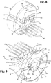
- the pressure sensor 1 comprises a circuit arrangement supported by the sensor body 2. This arrangement is represented in a partial and schematic way in Figures 6 and 7 , in isolation from the sensor body, where it is designated as a whole by 5.
- the circuit arrangement 5 comprises a first electrical circuit pattern, designated as a whole by 6 in Figures 6 and 7 , designed to be at the face 2b of the body 2.
- the circuit pattern 6 comprises a plurality of tracks made of electrically conductive material, for example a metal or a metal alloy (such as a silver-palladium alloy), preferably silk-screen printed or in any case deposited on or associated to the face 2b of the body 2, on its side external to the cavity 3, as is visible, for example, in Figure 8 .
- Some of the aforesaid tracks are designated by 6a in Figures 6-8 . Consequently, in the preferred embodiment, the insulating material constituting the body 2 is exploited directly as substrate for at least part of the circuit arrangement 5.
- circuit pattern 6 Connected to the circuit pattern 6 is a plurality of corresponding circuit components, comprising means for detecting bending or deformation of the membrane 3, for example of any type known in the sector, as mentioned in the introductory part, such as a bridge of resistors, or piezo-resistors, or piezo-resistive elements, referred to hereinafter for brevity also as “resistances", irrespective of the corresponding connection or configuration.
- FIG. 7 and 8 designated by R are four resistances forming parts of a sensing bridge, made of resistive or piezo-resistive material (for example, a resistive or piezo-resistive paste) deposited on the face 2b at the membrane portion 3, in particular in a region thereof subject to elastic deformation, and connected to respective tracks 6a of the circuit pattern 6.
- the control electronics of the pressure sensor 1 is in a remote position and connected to the circuit arrangement 5 via suitable terminals (described hereinafter).
- control electronics of the sensor may include one or more components - for example, processing components and/or amplification components, such as integrated circuits or chips - supported directly by the sensor body 2 and electrically connected to one of its circuit patterns, in particular to the circuit pattern 6.
- processing components and/or amplification components such as integrated circuits or chips - supported directly by the sensor body 2 and electrically connected to one of its circuit patterns, in particular to the circuit pattern 6.
- circuit pattern 6 with the corresponding components R, is coated with a protective layer L1 of electrically insulating material, such as a layer of polymeric or vitreous material.
- the circuit arrangement 5 comprises a second electrical circuit pattern, designated as a whole by 7 in Figures 6 and 7 , which is located at the face 2a of the body 2.
- the circuit pattern 7 comprises one or more tracks of electrically conductive material, for example a metal or a metal alloy (such as a silver-palladium alloy), for example silk-screen printed or deposited on, or in any case associated to, a region of the face 2a that is in a position peripheral with respect to the opening of the cavity 3.
- one or more of the circuit patterns 6 and 7 comprises/comprise a plurality of tracks of electrically conductive material, such as a metal or a metal alloy, which are fixed or glued or engraved on the respective face 2b and 2a of the body 2, or else tracks fixed or glued or deposited or silk-screen printed or engraved on a different support, such as a circuit support, associated to the body 2.
- electrically conductive material such as a metal or a metal alloy
- a track of the circuit pattern 7 at least partially surrounds the opening of the cavity 3.
- the track designated by 11 surrounds the opening of the cavity 3 completely.
- the aforesaid track has a circular closed-ring shape and is set around the opening of the cavity 3, in particular to define an area resting on which, directly or with interposition of a layer of other material, is a circular sealing element, such as an O-ring.
- electrically connected to the second circuit pattern 7 is at least one circuit component, in particular a sensor means for detecting a physical characteristic or quantity of the fluid other than the pressure.
- this component - designated as a whole by 8 - has an active part 8a that is to be exposed to the fluid and at least two connection terminals 8b.
- the component 8 is a temperature sensor, such as a resistor performing functions of temperature sensor, for example an NTC (negative-temperature coefficient) resistor, the active part 8a of which (i.e., the part performing sensing functions) is to be exposed directly to the fluid in order to carry out direct detection of temperature.
- NTC negative-temperature coefficient
- the terminals 8b of the sensor 8 are in the form of reophores or legs, designed to be soldered to respective connection pads, belonging to the circuit pattern 7.
- a surface-mount (SMD) type preferably provided with small metal terminals, for example in the form of pads or metallized ends, designed to be soldered directly on conductive tracks of a circuit pattern, in particular using a solder paste.
- Components of an SMD type that may be used for the purposes of implementation of the invention preferably have small dimensions, also so as to be more easily coated with a possible protective material, such as a thermally conductive but electrically insulating material and/or a material for protection against corrosion.
- a possible protective material such as a thermally conductive but electrically insulating material and/or a material for protection against corrosion.
- the pressure sensor according to the invention is designed for possible use in combination with electrically conductive liquids
- an appropriate electrical insulation of the electrical parts (such as electrical tracks and components) exposed to the fluid for example via a protective polymeric coating, or a coating made of vitreous material or some other electrically insulating material; as has been said, this type of protection may be facilitated by the use of electronic components of an SMD type.
- circuit pattern 7 is prevalently coated with a protective layer L2 of electrically insulating material, such as a layer of polymeric or vitreous material, which is locally open at pads for connection of the sensor 8, or in any case shaped so as to leave these pads exposed to enable soldering or connection of the terminals of the sensor 8.
- a protective layer L2 of electrically insulating material such as a layer of polymeric or vitreous material, which is locally open at pads for connection of the sensor 8, or in any case shaped so as to leave these pads exposed to enable soldering or connection of the terminals of the sensor 8.
- annular sealing element 9 in particular of an O-ring type, is designed to rest directly on the protective layer L2 and circumscribes a region where the opening of the cavity 3 is located and within which the sensor 8 is positioned.
- the protective layer L2 is absent or does not cover the annular track 11 of the circuit pattern 7.
- an annular sealing element similar to the one designated by 9, in particular of an O-ring type, is designed to rest directly on the track 11 and circumscribes a region where the opening of the cavity 3 is located and within which the sensor 8 is positioned.
- the circuit arrangement 5 moreover comprises contacts or terminals for electrical connection of the sensor 1 to a generic external system (such as the control electronics of the sensor), the contacts or connection terminals of which are connected to electrically conductive tracks of at least one of the circuit patterns 6 and 7.
- terminals (some of which are designated by 10) are provided, which extend longitudinally and are made of electrically conductive material and are mechanically coupled to the face 2b of the sensor body 2 in an area that is peripheral with respect to the membrane portion 3 and electrically connected to tracks 6a of the circuit pattern 6.
- the terminals may have a different form, for example they may be of an elastic or spring type, or represented by simple pads or contacts, or be obtained according to other techniques in themselves known.
- the circuit pattern 7 comprises a track that defines, or that is electrically connected to, at least one pad, for connection of a terminal or reophore 8b of the circuit component represented here by the sensor 8.
- the aforesaid track designated by 11, has an annular shape and is obtained by deposition of conductive material, for example of the type mentioned above, on the face 2a of the sensor body, to surround the opening of the cavity 3.
- Designated by 12a is the aforesaid pad for connection of a reophore 8b of the sensor 8, which is preferably located within the ring defined by the track 11 and is connected to the latter via a corresponding portion of track 11a (see also Figure 12 ).
- the pad 12a preferably has the same thickness as the track 11, but represented in the figures, on its upper side, is a filler material - for example a solder paste - used for electrical and mechanical connection of the corresponding reophore 8b of the sensor 8.
- the circuit arrangement 5 further comprises means for electrically connecting together the two circuit patterns 6 and 7, i.e., for connecting the circuit pattern 7 directly or indirectly (via the circuit pattern 6) to one or more respective terminals 10.
- connection means comprise at least one track or metallization obtained in a respective through hole of the sensor body 2, which extends axially between the faces 2a and 2b.
- two of these holes are provided with surface metallization: these holes, which are preferably but not necessarily in positions substantially opposite with respect to the opening of the cavity 3, are designated by 14 and 15 in Figure 5 .
- each hole 14 and 15 located on the inner surface of each hole 14 and 15 is a respective layer of electrically conductive material or "metallization", for example of the type already referred to above, which extends throughout the length and/or surface of the corresponding hole, as far as its two ends, preferably coming out therefrom on the faces 2a and 2b of the body 2, in particular to form, or be connected to, respective contact pads, such as circular pads or electrical tracks, possibly forming part of the circuit patterns 6 and/or 7.
- respective contact pads such as circular pads or electrical tracks
- connection means between the circuit patterns 6 and 7 will be defined also as "metallized holes”.
- the layers of conductive material in the holes 14 and 15 are designated by 14a and 15a, for example in Figures 6 and 7 , and preferably have a tubular or hollow cylindrical shape, it being, however, possible for them to have a different configuration. If need be, the holes 14 and 15 could be at least partially filled with other material, such as a soldering material and/or a sealant.
- the layers 14a, 15a may be obtained with any technique known in the sector, for example via deposition, or silk-screen printing, or filling and suction.
- 14b and 15b are the contact pads defined at or connected to the lower ends of the layers 14a and 15a, i.e., at the face 2a of the sensor body 2; designated, instead, by 14c and 15c are the contact pads defined at or connected to the upper ends of the layers 14a and 15a, i.e., at the face 2b of the sensor body 2.
- the pads 14b, 15b, 14c, 15c preferably have an annular shape; i.e., they are open at the centre.
- the conductive layer 14a is designed to connect the track 11 of the circuit pattern 7 to a first terminal 10, via a track 6a of the circuit pattern 6.
- the end pad 14b is connected to the track 11 via a respective portion of track 11b (see also Figure 12 ), whereas the end pad 14c is connected to the aforesaid first terminal 10 via a track 6a.
- 12b is a second pad for connection of the second reophore 8b of the temperature sensor 8.
- This pad 12b which is also represented in various figures with the soldering material of the corresponding reophore 8b, is preferably located within the ring defined by the track 11.
- the pad 12b is electrically insulated from the track 11 and, in the example, is connected to the conductive layer 15a of the hole 15, which is in turn electrically connected to a second terminal 10, via the circuit pattern 6.
- the pad 12b is connected, for example via a corresponding conductive track 13 of the circuit pattern 7, to the end pad 15b and hence to the layer 15a (see also Figure 11 ), whereas the end pad 15c is connected to the aforesaid second terminal 10 via a further track 6a of the circuit pattern 6.
- the pads 12a, 12b for connection of the temperature sensor 8 are in positions diametrally opposite to the cavity 3, but this does not constitute an essential characteristic, it being possible to locate them in other areas within the track 11.
- the metallized hole or each metallized hole of the sensor 1 is occluded via a closing member having a pre-formed body, i.e., a body on which there is bestowed a substantially predefined shape before it is mounted on the sensor body.
- a closing member having a pre-formed body, i.e., a body on which there is bestowed a substantially predefined shape before it is mounted on the sensor body.
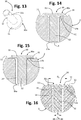
- designated for this purpose by 30 are the members for closing the metallized holes 14-14a and 15-15a, a possible embodiment of which is illustrated in Figures 13-16 , where the pre-formed body is designated by 30a.
- the pre-formed body 30a of each member 30 has at least one closing portion 31.
- the closing portion 31 is cylindrical or shaped like a disk having a diameter D 1 larger than that of the corresponding hole 14 or 15, or else comprises at least one circular part having such a diameter D 1 that is designed to rest on at least one corresponding pad 14b or 15b.
- the closing portion 31 may have a different perimetral profile or cross-sectional dimension (i.e., a cross-sectional dimension in a direction radial or orthogonal with respect to the axis of the hole), but in any case a shape inscribed in which is an imaginary circular region of diameter D 1 (for example, the portion 31 could have a polygonal shape, inscribed in which is an imaginary cylindrical or disk-shaped portion of diameter D 1 ).
- the diameter D 1 of the closing portion 31 is larger than the diameter D H of the hole 14 (or 15) provided with the corresponding metallization 14a (or 15a). In this way, the closing portion 31 remains on the outside of the metallized hole 14-14a (or 15-15a), it being able to cover completely the corresponding end opening thereof.
- the diameter D 1 is predefined in the stage of design of the closing portion 31, such as to cover or close completely the corresponding end opening of the metallized hole 14-14a or 15-15a, even in the conditions of different tolerances of size of the device 1 and/or of positioning of the closing member 30 with respect to the corresponding metallized hole that are typical of industrial production of sensors or circuits.
- the pre-formed body 30a of the closing member 30 comprises, in addition to the closing portion 31, also a positioning or centring portion, designated by 32 (hereinafter defined for brevity also simply as “centring portion”), which extends underneath the portion 31.
- the centring portion 32 has a cylindrical or tubular shape having a diameter D 2 smaller than the diameter D 1 , in particular smaller than that of the corresponding metallized hole 14-14a, 15-15a.
- the centring portion 32 may have other shapes suited to the purpose, and in particular a shape designed to be inscribed or contained in a circle of diameter D 2 (for example, a polygonal or star shape that can be inscribed in a circle of diameter D 2 ).
- the centring portion 32 has a diameter D 2 ( Figure 16 ) that is smaller than the diameter D H of the metallized hole: in this way, the centring portion 32 facilitates mounting of the member 30 on the sensor body 2, moreover ensuring correct positioning of the closing portion 31 relative to the metallized hole.
- the diameters of the hole with the corresponding metallization, of the closing portion 31, and of the centring portion 32 are such that, for any centring position that may be assumed by the portion 32 in the metallized hole, the closing portion 31 always obstructs the end opening of the hole.
- Figures 14 and 15 illustrate a position of the portion 32 perfectly centred in the hole ( Figure 14 ) and a position completely off centre of the portion 32 in the hole, i.e., up against the conductive layer 14a ( Figure 15 ): as may be noted, also in this position, the portion 31 covers the end opening of the metallized hole 14-14a completely.
- the positioning or centring portion 32 may also have a shape and size such as to cause an albeit minimal interference with the inner surface of the hole 14 (or 15), i.e., with the corresponding metallization 14a (or 15a), in particular in order to cause a mutual mechanical fixing, for example in order to keep the closing member 30 temporarily in position, in particular in the steps that precede fixing or soldering of the closing portion 31 to the circuit pattern 7 and/or to the corresponding pad 14b or 15b.
- the centring and/or fixing portion 32 could also have a shape that is at least in part conical, or else have two different diameters of which one is designed to provide the aforesaid interference or again presents a surface knurling or is shaped with radial reliefs (for example, with a cross section substantially shaped like a star, with points of the star designed to provide the aforesaid interference with the corresponding metallized hole 14a).
- the shape and/or sectional dimensions of the portion 32 will be chosen so as to cause an interference that will not damage or will not jeopardize operation of the metallization 14a or 15a, for example a shape that, if need be, is in part deformable.
- the closing portion 31 is preferably shaped like a plate, whilst the portion 32 - if present - preferably has the shape of a pin or relief projecting from the portion 31.
- the portion 32 comprises a number of parts in relief, such as three pins arranged in a triangle or a number of pins arranged at the vertices of a polygon that can be inscribed in a circle of diameter D 2 or D H .
- the portions 31 and 32 have a circular outer profile, the former being shaped like a small disk and the latter being cylindrical. It will be appreciated, however, that - as has been said - these shapes, albeit preferred, are not strictly essential for the purposes of implementation of the invention, and may be different.
- the portion 31 could in fact have a peripheral profile that is polygonal, elliptical, etc.; similar considerations apply to the portion 32, if present.
- the upper side or surface of the portion 31 could have a shape different from the one here represented as plane, for example at least in part curved or prismatic, for instance hemispherical.
- the underside or lower surface of the portion 31 could have a shape different from the one here represented as plane, but in any case such as to perform the function of closing the corresponding metallized hole.
- the lower surface of the portion 31 could be in part curved or prismatic, for example recessed.
- the lower surface of the portion 31 is preferably provided with a profile designed to mate in a uniform way with the area of the pads 14b or 15b, such as a plane coupling profile or surface: this also in order to obtain a good fluid-tightness against any infiltration of the fluid into the coupling area, in particular after a corresponding gluing or soldering.
- the peripheral and/or upper and/or lower surfaces of the portion 31 preferably have a shape designed to enable easy soldering or fixing of the portion 31 to the pads 14b or 15b and/or a shape designed to enable a further coating of the portion 31 via a coating and/or protective material, such as a resin or a sealant.
- the shape of the portion 31 of the member 30 is such as to provide also an electrical terminal, preferably via a relief that extends from the upper face of the portion 31, for example for soldering and/or fixing of a component of the circuit arrangement (for instance, an electrical terminal of the sensor 8: in this case, the terminal of the sensor 8 may be connected directly to the member 30 instead of to a corresponding pad 12a or 12b).
- the metallized holes 14-14a, 15-15a do not necessarily need to have a circular cross section either.
- the term "diameter” used here is hence to be understood in general, and consequently also as indicating perimetral dimensions or cross-sectional dimensions of the body 30a of the closing member 30 that correspond to an area or a perimeter or a cross section of the portions 31 and/or 32 and/or of the corresponding metallized hole.
- the pre-formed body 30a of the member 30, whether comprising or not the centring portion 32, is preferably made of at least a metal material or a metal alloy, such as copper, or copper alloys, preferably tinned or coated with other metal or alloy, in particular a material designed to facilitate soldering or gluing.
- the pre-formed body 30a is made of a single piece, obtained for example via machining operations, such as blanking and/or upsetting and/or turning, or else the member 30 is formed at least in part via stamping, such as deformation using a die or injection of molten metal material into a die.
- the body 30a of the member 30 (even when it comprises only the closing portion 31) is obtained starting from a metal bar appropriately machined via turning, or else from a metal bar shaped via blanking and/or stamping; alternatively, an end portion of a metal bar could be deformed via an upsetting operation to obtain the portion 31.
- the body 30a of the member 30 may be also obtained via a process of micromelting or stamping of molten metal material.
- the closing member 30 and/or at least the portion 31 of its body 30a is preferably made of a material having a hardness and/or a mechanical strength greater than that of the materials commonly used for occluding the metallized holes provided according to the known art, in particular a material having a deformation strength and/or a shear strength greater than those of an alloy for soldering circuits.
- the member 30, and in particular its closing portion 31, enables a sealing or closing of the metallized hole 14 to be obtained that is substantially immune from any deformation or extrusion, which is typical instead of the masses of soldering or closing material used in the traditional technique, as exemplified in Figures 1A-1C .
- the shape and/or dimensions of the body 30a or of its portion 31 are preferably defined also taking into account the corresponding material, for example it being possible to define a diameter and/or a thickness of the portion 31 that is all the smaller (obviously compatibly with the diameter of the metallized holes), the higher the mechanical strength of the material used.
- the annular area of resting of the portion 31 of the member 30 on the pad 14b or 15b may be defined beforehand so that it will be possible to withstand the thrust loads due to the pressure of the fluid.
- the aforesaid annular area substantially corresponds to the circular area defined by the diameter D 1 minus the circular area defined by the diameter D H of the circular hole, not considering the area defined by a possible chamfer.
- the thickness and shape of the portion 31 of the member 30 may be determined in such a way as to define a substantially annular area capable of withstanding the force or pressure of the fluid, in particular a pressure of some hundreds of bar and/or a force in a direction substantially parallel to the axis of the metallized hole 14, 15, such as a force of some kilograms, for example a pressure comprised between 1 kg/mm 2 and 4 kg/mm 2
- the aforesaid substantially annular area of resting of the portion 31 is preferably greater than the area corresponding to the metallized hole 14-14a, 15-15a, in particular a value of surface corresponding to at least twice the area that corresponds to the metallized hole 14-14a, 15-15a.
- the portion 31 may have a thickness comprised between approximately 0.15 and 0.3 mm, preferably approximately 0.2 mm.
- the portion 31 may have a diameter D 1 of between approximately 1 mm and approximately 1.6 mm, preferably 1.4 mm, whereas the portion 32 - if present - may have a diameter D 2 of between approximately 0.59 mm and approximately 0.99 mm, preferably 0.6 mm.
- the end of the metallized hole where a closing member 30 is to be mounted, provided with centring portion 32 is shaped so as to define a lead-in portion or a flaring, for example a chamfered profile or a profile inclined with respect to the axis of the hole in order to facilitate insertion of the portion 32 into the hole.
- the end of the hole 14 includes a substantially frustoconical stretch, designated by FC only in Figures 14-16 , with the corresponding conductive layer 14a or 15a that has a corresponding shape in this region.
- the lower end of the portion 32 is shaped so as to favour insertion of the portion itself in the metallized hole; in the case exemplified, this lower end has a profile or a chamfered, or inclined, or rounded peripheral edge, designated by 32a only in Figure 13 , but other shapes suitable for the purpose are obviously possible, such as a generally pointed or hemispherical shape or a frustoconical shape that is more marked as compared to the case illustrated.
- At least one portion of the pre-formed body 30a of the member 30, preferably its closing portion 31, is fixed in a fluid-tight way to the corresponding metallized hole.
- the aforesaid portion 31 is fixed in position via at least one of a fixing material and a sealing material, for example a soldering material, a gluing material, or a resin.
- a first material may be provided for local fixing in position and/or for obtaining a first seal of the portion 31, and a second material may be provided for guaranteeing or improving the necessary fluid-tightness of the portion 31 with respect to the corresponding metallized hole.
- the first fixing and/or sealing material may be a soldering or gluing material
- the second sealing material may be a soldering material, or a resin, or a polymer.
- a single material is provided, which performs simultaneously functions of fixing in position and functions of tightness, such as a soldering material (for example, a metal alloy), or a gluing material, or a resin, or a polymer.
- a soldering material for example, a metal alloy
- gluing material for example, a resin
- a polymer such a material, which simultaneously performs fixing and sealing functions, is designated by 35.
- the material 35 is set at least on the end face of the sensor so as to surround the closing portion 31 of the member 30 peripherally in order to ensure fluid-tightness between this face and the peripheral surface of the portion 31.
- the material 35 used presents characteristics such as to fix the member 30 in position, in addition to guaranteeing the necessary fluid-tightness.
- the material 35 is a material or a metal designed to weld or bond chemically and/or structurally to the material of the portion 31 and to the material of the corresponding pad 14b or 15b.
- the material 35 may also be deposited so as to extend at least in part over the upper surface of the portion 31 and/or coat this portion completely, possibly extending at least in part between its lower surface and the corresponding pad 14b or 15b.
- the fixing and/or sealing material is a weld material or an added material, with the body 30a of the member 30 that is fixed in position in a fluid-tight way via soldering or sealing or gluing.
- the fixing and/or sealing material is a material that provides or coats at least in part one of the closing member 30 and the circuit pattern 7 and pads 14b, 15b, with the portion 31 of the member 30 that is fixed in position in a fluid-tight way via soldering.
- the body 30a of the member 30 and/or the pads 14b, 15b may be initially coated with a soldering material (for example, they may be pre-tinned), this material being is then remelted to bring about sealing and/or fixing, and hence without any need for a further addition of solder alloy.
- such a material designed to remelt may be provided within a metallized hole, the material coating the corresponding metallization at least in the part of hole that is to receive a portion of the pre-formed body, for example the portion 32.
- the material designed to remelt may also comprise a surface layer of part of the pre-formed body or of the metallization of the hole.
- the end pad 14b or 15b where the member 30 is located has a diameter larger than the diameter of the closing portion 31.
- the diameter of the portion 31 of the member 30 and the diameter of the pad 14b or 15b in question are such that, for any position of centring of the former with respect to the latter , a peripheral annular part of the pad projects laterally from the closing portion 31. Also this concept emerges from the comparison between Figures 14 and 15 .
- the fixing and/or sealing material such as the material 35, in particular a weld or added material, may be a material used for fixing or soldering together at least the aforesaid peripheral part of the pad in question and the lateral surface of the closing portion 31 of the member 30, as exemplified for instance in Figures 14-16 .
- the material 35 in the case of soldering, is preferably a metal material or a metal alloy, for example with a base of indium, and/or tin, and/or lead.
- the material 35 is a solder paste or a glue designed to ensure positioning and fluid-tightness at high pressures, preferably pressures of up to at least 400 bar.
- FIGs 17-19 illustrate an embodiment according to which the pre-formed body 30a of the closing members, here designated by 30', consists only of the closing portion 31, here exemplified in the form of a disk-shaped plate, which may be made and/or fixed according to what is described in reference to the previous example of Figures 13-16 .
- This type of implementation presupposes a higher operating precision in positioning of the member 30 at the end of the corresponding metallized hole, given the absence of a centring portion, but presents the advantage of simplifying the formation of the member itself, which, for example, may be obtained via blanking from a metal strap.
- This solution enables also saving of material for production of the pre-formed body.
- the members 30' fixed in position via the corresponding material 35 ensure closing in a fluid-tight way of the metallized holes, without any risk of deformation and/or extrusion with consequent passage of the fluid, as described in the introductory part of the present disclosure.
- the pre-formed body 30a of the closing member extends on the outside of the corresponding metallized hole, as in the case of the member 30', or else extends only partially into the corresponding hole, for a limited stretch of the length of the hole itself, as in the case of the member 30. In this way, any risk of anomalous electrical contacts or even failure of the closing member following upon thermal expansion are prevented.
- closing members 30' external to the hole or of closing members 30 that extend only partially into the metallized hole, for a limited part of its length.
- the closing member is fixed in position at just one end of the hole; i.e., it is not fixed at the other end of the same hole, thereby preventing mechanical stresses that could be the cause of cracks or failure following upon thermal expansion.
- the closing members 30 and/or 30' may have a shape and/or dimensions such as to enable easy handling thereof for them to be picked up, and/or moved, and/or positioned for their installation on the pressure sensor 1.
- a shape and size may be chosen to enable handling of a member 30 or 30' using a small suction pad or a suction device or vacuum device, such as a device for manual pick-up or a device belonging to an automatic assembly system.
- an automated system may be used of the type employed for handling and mounting SMD components, such as a system of the pick-and-place (P&P) type, which in particular is designed to pick up the closing member 30 or 30' via suction or vacuum.
- P&P pick-and-place
- the upper part of the portion 31 of the body 30a may be provided with a surface designed for the P&P system, such as a smooth surface or a surface finished in such a way as to enable tightness when suction is exerted by a small suction pad or when vacuum is brought about.
- the closing members 30 or 30' may be pre-arranged in purposely provided containers or on strips, in particular in a position such as to expose the aforesaid upper surface of the portion 31.
- the circuit pattern 7 is practically entirely coated with a protective layer L2 of electrically insulating material, in particular a vitreous or polymeric material, applied on the face 2a of the body 2.
- the protective layer L2 has passages or openings (not represented) so as to leave exposed the connection pads 12a and 12b of the sensor 8, as well as passages or openings so as to leave exposed the pads 14b, 15b and the head of the closing members 30, with the corresponding fixing and/or sealing material, for example the material 35, that performs both of functions.
- the layer L2 could be provided following upon mounting of the sensor 8 and/or of the members 30, also so to coat at least partially the pads 12a, 12b and/or the pads 14b, 15b, and/or the portion 31 of the members 30 or 30' with the corresponding material 35.
- the layer L2 is deposited - for example via silk-screen printing - in way such that at least an annular part of its upper surface is as a whole substantially plane in order to provide a resting surface for the annular seal 9.
- the circuit pattern 7 comprises an annular track 11, so that such an annular track or the part of the layer L2 that covers it will enable simple definition of a uniformly plane resting base for the seal 9.
- the diameter of the track 11 could even be smaller than the diameter of the seal 9, in which case the latter can rest on the lower face 2b of the sensor body 2, possibly also in an peripheral area thereof not presenting parts of the circuit arrangement or a protective layer L2 (in a way similar to what is illustrated in Figure 22 ).
- both the pads 12a and 12b and the members 30 that close the upper ends of the metallized holes are located within the region circumscribed by the seal 9, thereby being exposed to the fluid. Provision of a member 30 with the corresponding sealing and fixing material enables solution of the problems highlighted in the introductory part of the present description.
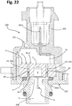
- Figures 21 and 22 are schematic illustrations of an example of device for detecting the pressure of fluids that integrates a pressure sensor according to one of the embodiments described previously, and namely a sensor 1, preferably but not necessarily with a protective layer L2 of the type described with reference to Figures 2 and 20 .
- a device designated as a whole by 100, may find use, for example, in the automotive sector, or in the domestic sector and the sector of electrical household appliances, or in the HVAC, plumbing, and sanitary sector.
- the device 100 has a casing body, formed for example by at least two body components 101, 102, coupled in a fluid-tight way so as to define between them a housing for the sensor 1.
- the component 101 defines a tubular part 103 of an electrical connector
- the component 102 defines an inlet 104, designed to be connected to a circuit, located in which is the fluid of which the pressure and temperature are to be detected (assuming - as in the case considered here - that the component 8 is a temperature sensor).
- FIG. 22 Visible in Figure 22 is the housing defined between the two components 101, 102, within which the sensor 1 is fixed with modalities in themselves known. From the figure it may moreover be noted how extending within the tubular part 103 of the component 101 are connection terminals 103a, with which the terminals 10 of the pressure sensor 1 are electrically in contact.
- the pressure sensor 1 is mounted within the casing body 101-102 so that its lower face - located in which is the opening of the cavity 3 - faces the inlet 104, within which the temperature sensor 8 preferably projects.
- Mounted between an upper face of the component 102 and the pressure sensor 1 is the seal 9.
- the aforesaid upper face of the component 102 is purposely provided with a positioning seat 102a for the seal 9, which rests on the opposite side on the lower face of the sensor, as explained previously.
- the seal 9 delimits peripherally a chamber or a volume V, within which the closing members 30 of the metallized holes are located.
- the fluid at inlet from the passage 104 can reach the cavity 3 of the sensor body 2, causing a bending thereof proportional to the pressure, which is measured via the corresponding sensing means R.
- the fluid also impinges upon the sensor 8, enabling detection of the further quantity of interest, here represented by the temperature of the fluid.
- the presence of the closing members 30 prevents any possible leakage of the fluid being detected through the metallized holes 14-14a and 15-15a, as explained previously.
- the senor - here designated as a whole by 1' - has a body made up of at least two distinct parts, comprising a first main body part 2', defining the corresponding axial cavity 3, which is closed in at the face 2b, in particular by a corresponding portion 4', which here does not perform the membrane function.
- the sensor body then comprises a membrane part 4", fixed in a fluid-tight way to the body part 2', in a known way, at the opposite end of the cavity 3, i.e., at the face 2a.
- the face 2a is provided with a recess (not shown), which is substantially coaxial to the cavity 3, within which the membrane 4' is fixed, the recess and membrane preferably having a similar peripheral profile.
- the aforesaid recess may be absent.
- the side of the membrane 4" external to the cavity 3 is exposed to the fluid of which the pressure is to be detected, whereas its opposite side, facing the inside of the cavity 3, carries at least one circuit component R for detecting bending or deformation of the membrane 4".
- the at least one component R may comprise, for example, a plurality of piezoelectric, piezo-resistive, or resistive elements, or else a respective part of a capacitive detector, the other part of which is associated to the main body 2', for example according to techniques in themselves known.
- the at least one component R is connected to the circuit pattern 6 provided on the face 2a via metallized holes 14' and 15', which are made in a way similar to the holes 14-14a and 15-15a.
- the holes 14' and 15' do not require respective closing members of the type designated by 30 or 30', given that the lower end thereof is in any case in a protected position, thanks to the presence of the membrane 4".
- the circuit pattern 6 is substantially of the type already described and illustrated previously, obviously modified with tracks and/or pads necessary for connection of the metallized holes 14' and 15'.
- the sensor 8 for example a temperature sensor, mounted at the face 2a and electrically connected to the circuit pattern 6 via the circuit pattern 7 and the metallized holes 14-14a and 15-15a.
- the circuit pattern 7 is similar or substantially similar to what has already been described previously, for example with at least one corresponding track of electrically conductive material, in particular an annular track, which is located on a region of the face 2a that at least partially surrounds the membrane 4".
- the metallized holes 14-14a and 15-15a are made in a way similar or substantially similar to what has already been described, with the corresponding closing members 30 (or possibly 30').
- the senor 1' is of the third type described in the introductory part of the present disclosure; i.e., the sensor body 2', 4" has a passage for setting the inside of the cavity 3 in communication with the outside.
- a passage - designated by 16 - is configured as a through hole of the portion 4' of the body 2', thus giving rise to a pressure sensor of the type generically known as "relative pressure sensor”.
- the passage 16 may be omitted or else sealed in the production stage, in which case the sensor 1' will be of the second type referred to in the introductory part, thus giving rise to a pressure sensor of the type generically known as "absolute pressure sensor", i.e., one presenting a known reference pressure within the hermetically closed cavity 3.
- absolute pressure sensor i.e., one presenting a known reference pressure within the hermetically closed cavity 3.
- the fluid at inlet from the passage 104 can impinge upon the exposed side of the membrane 4", causing a bending thereof proportional to the pressure, which is measured via the corresponding sensing means R.
- the fluid also impinges upon the sensor 8, enabling detection of the further quantity of interest, here represented by the temperature of the fluid.
- the electrically conductive track referred to in Figures 6 and 7 , with the associated pads and/or the protective layers LI, L2 can be obtained on the sensor body 2 with techniques other than silk-screen printing, even though this is the preferred technique; for example, alternative techniques in this sense may be selected from among lithography, photolithography, spraying or a jet of conductive material, surface metallization, plating, etc.
- the senor forming the subject of the invention may be equipped with a plurality of additional components of the type previously designated by 8, such as resistors or sensors, for example with electrical connection in parallel or else via a connection to further pads and tracks of the type exemplified.
- the structure of the circuit pattern 7 could be of the type described in WO 2014/097255 , i.e., configured for enabling connection of alternative components and/or connection according to a number of alternative modalities of one and the same component.
- the circuit pattern 7 could comprise a number of concentric conductive tracks or, instead of a single tracks 11, a plurality of tracks could be provided forming an arc of circumference.
- the metallized holes could even number more than two, according to the circuit needs, at least one of which having an end located in an area that can be reached by the fluid, and hence provided with the corresponding closing member 30.
- a fixing and/or sealing material that extends between the lower surface of the portion 31 and the corresponding pad 14b or 15b, and possibly between part of the outer surface of the portion 32 and a corresponding part of the surface of the corresponding metallized hole.
- a fixing and/or sealing material 35 Such a case is exemplified schematically in Figure 24 , where the same reference numbers as those of the previous figures are used to designate elements that are technically equivalent to the ones already described, amongst which a fixing and/or sealing material 35.
- the arrows F1 are aimed at representing schematically the pressure of the fluid impinging upon the closing portion 31 of the member 30.
- the fixing and/or sealing material 35 between the lower surface of the portion 31 and the corresponding pad 14b (or 15b) has in any case a reduced thickness, in particular such as a thin layer or film.
- the area of the material 35 possibly subjected to the pressure of the fluid on its outer profile substantially corresponds to the aforesaid reduced thickness of the material 35.
- the material 35 is thus able to withstand high mechanical stresses, or forces, or pressures F2 of the fluid, even though the material itself has a hardness or strength lower than that of the closing member 30. Similar considerations also apply in the case where the layer of fixing and/or sealing material that extends underneath the portion 31 of the member 30 belongs to a mass of the same material that also surrounds the portion 31 peripherally and/or coats it at least in part.
Landscapes
- Physics & Mathematics (AREA)
- General Physics & Mathematics (AREA)
- Chemical & Material Sciences (AREA)
- Analytical Chemistry (AREA)
- Measuring Fluid Pressure (AREA)
Priority Applications (3)
| Application Number | Priority Date | Filing Date | Title |
|---|---|---|---|
| RS20200005A RS59754B1 (sr) | 2015-04-16 | 2016-04-15 | Senzor za detekciju jedne ili više veličina fluida, posebno senzor pritiska |
| PL16722379T PL3283865T3 (pl) | 2015-04-16 | 2016-04-15 | Czujnik do pomiaru jednego albo większej liczby parametrów płynu, w szczególności czujnik ciśnienia |
| SI201630553T SI3283865T1 (sl) | 2015-04-16 | 2016-04-15 | Senzor za odkrivanje ene ali večih količin fluida, posebno senzor tlaka |
Applications Claiming Priority (2)
| Application Number | Priority Date | Filing Date | Title |
|---|---|---|---|
| ITUB2015A000460A ITUB20150460A1 (it) | 2015-04-16 | 2015-04-16 | Sensore per la rilevazione di una o piu' grandezze di un fluido, particolarmente un sensore di pressione |
| PCT/IB2016/052153 WO2016166712A1 (en) | 2015-04-16 | 2016-04-15 | A sensor for detecting one or more quantities of a fluid, in particular a pressure sensor |
Publications (2)
| Publication Number | Publication Date |
|---|---|
| EP3283865A1 EP3283865A1 (en) | 2018-02-21 |
| EP3283865B1 true EP3283865B1 (en) | 2019-10-16 |
Family
ID=53490185
Family Applications (1)
| Application Number | Title | Priority Date | Filing Date |
|---|---|---|---|
| EP16722379.1A Active EP3283865B1 (en) | 2015-04-16 | 2016-04-15 | A sensor for detecting one or more quantities of a fluid, in particular a pressure sensor |
Country Status (12)
| Country | Link |
|---|---|
| US (1) | US10627301B2 (sr) |
| EP (1) | EP3283865B1 (sr) |
| CN (1) | CN107548452B (sr) |
| DK (1) | DK3283865T3 (sr) |
| ES (1) | ES2766849T3 (sr) |
| HU (1) | HUE047161T2 (sr) |
| IT (1) | ITUB20150460A1 (sr) |
| PL (1) | PL3283865T3 (sr) |
| PT (1) | PT3283865T (sr) |
| RS (1) | RS59754B1 (sr) |
| SI (1) | SI3283865T1 (sr) |
| WO (1) | WO2016166712A1 (sr) |
Families Citing this family (5)
| Publication number | Priority date | Publication date | Assignee | Title |
|---|---|---|---|---|
| DE102017213530A1 (de) * | 2017-08-03 | 2019-02-07 | Robert Bosch Gmbh | Niederdrucksensorvorrichtung und Verwendung eines Einlassstutzens als Fluideinlass für eine Niederdrucksensorvorrichtung |
| IT201900019274A1 (it) * | 2019-10-18 | 2021-04-18 | Metallux Sa | Sensore di pressione |
| KR102843254B1 (ko) * | 2020-05-04 | 2025-08-05 | 주식회사 엘지에너지솔루션 | 커넥터 모듈 |
| CN114636510A (zh) * | 2020-12-15 | 2022-06-17 | 浙江三花汽车零部件有限公司 | 传感器组件以及阀装置 |
| JP7567472B2 (ja) * | 2020-12-28 | 2024-10-16 | 富士電機株式会社 | 半導体パッケージ、樹脂成形品および樹脂成形品の成形方法 |
Citations (1)
| Publication number | Priority date | Publication date | Assignee | Title |
|---|---|---|---|---|
| US20060094219A1 (en) * | 2004-11-01 | 2006-05-04 | Nec Electronics Corporation | Method for manufacturing electronic device |
Family Cites Families (7)
| Publication number | Priority date | Publication date | Assignee | Title |
|---|---|---|---|---|
| US4658651A (en) * | 1985-05-13 | 1987-04-21 | Transamerica Delaval Inc. | Wheatstone bridge-type transducers with reduced thermal shift |
| US7659612B2 (en) * | 2006-04-24 | 2010-02-09 | Micron Technology, Inc. | Semiconductor components having encapsulated through wire interconnects (TWI) |
| ITTO20080483A1 (it) * | 2008-06-19 | 2009-12-20 | Eltek Spa | Dispositivo sensore di pressione |
| ITTO20080484A1 (it) * | 2008-06-19 | 2009-12-20 | Eltek Spa | Dispositivo sensore di pressione |
| IT1394791B1 (it) | 2009-05-20 | 2012-07-13 | Metallux Sa | Sensore di pressione |
| IT1401220B1 (it) * | 2010-07-15 | 2013-07-12 | Metallux Sa | Sensore e metodo di fabbricazione. |
| ITTO20121130A1 (it) * | 2012-12-21 | 2014-06-22 | Metallux Sa | Sensore di pressione |
-
2015
- 2015-04-16 IT ITUB2015A000460A patent/ITUB20150460A1/it unknown
-
2016
- 2016-04-15 US US15/566,136 patent/US10627301B2/en active Active
- 2016-04-15 RS RS20200005A patent/RS59754B1/sr unknown
- 2016-04-15 EP EP16722379.1A patent/EP3283865B1/en active Active
- 2016-04-15 WO PCT/IB2016/052153 patent/WO2016166712A1/en not_active Ceased
- 2016-04-15 PL PL16722379T patent/PL3283865T3/pl unknown
- 2016-04-15 DK DK16722379.1T patent/DK3283865T3/da active
- 2016-04-15 PT PT167223791T patent/PT3283865T/pt unknown
- 2016-04-15 CN CN201680022106.9A patent/CN107548452B/zh active Active
- 2016-04-15 HU HUE16722379A patent/HUE047161T2/hu unknown
- 2016-04-15 SI SI201630553T patent/SI3283865T1/sl unknown
- 2016-04-15 ES ES16722379T patent/ES2766849T3/es active Active
Patent Citations (1)
| Publication number | Priority date | Publication date | Assignee | Title |
|---|---|---|---|---|
| US20060094219A1 (en) * | 2004-11-01 | 2006-05-04 | Nec Electronics Corporation | Method for manufacturing electronic device |
Also Published As
| Publication number | Publication date |
|---|---|
| RS59754B1 (sr) | 2020-02-28 |
| WO2016166712A1 (en) | 2016-10-20 |
| US10627301B2 (en) | 2020-04-21 |
| DK3283865T3 (da) | 2020-01-27 |
| CN107548452A (zh) | 2018-01-05 |
| PL3283865T3 (pl) | 2020-05-18 |
| ITUB20150460A1 (it) | 2016-10-16 |
| PT3283865T (pt) | 2020-01-20 |
| HUE047161T2 (hu) | 2020-04-28 |
| US20180113042A1 (en) | 2018-04-26 |
| SI3283865T1 (sl) | 2020-02-28 |
| CN107548452B (zh) | 2020-02-14 |
| EP3283865A1 (en) | 2018-02-21 |
| ES2766849T3 (es) | 2020-06-15 |
Similar Documents
| Publication | Publication Date | Title |
|---|---|---|
| US10627301B2 (en) | Sensor for detecting one or more quantities of a fluid, in particular a pressure sensor | |
| EP2390641B1 (en) | Pressure Sensor | |
| US7900520B2 (en) | Pressure sensor device | |
| US8129624B2 (en) | Pressure sensor | |
| EP2813831A1 (en) | Physical quantity sensor and method for manufacturing physical quantity sensor | |
| US8156816B2 (en) | Pressure sensor | |
| US9625336B2 (en) | Pressure sensor and method for producing a pressure sensor | |
| KR20150083029A (ko) | 유체 매질의 온도 및 압력을 검출하기 위한 센서 | |
| KR19990082707A (ko) | 압력센서 | |
| US9759620B2 (en) | Pressure sensor | |
| US6725514B2 (en) | Method of making thick film pressure and temperature sensors on a stainless steel diaphragm | |
| CN108059124B (zh) | 将焊接附接的mems管芯自对准到安装表面的方法 | |
| US20170089792A1 (en) | Dampened pressure port | |
| EP3311118A1 (en) | Pressure ports and related methods | |
| JP7013298B2 (ja) | 圧力センサとその製造方法 | |
| EP1631803A1 (en) | A method for forming a pressure proof assembly between a component and house and such an assembly | |
| KR20260052920A (ko) | 압력 센서 장치 | |
| CN113049171B (zh) | 无引线压力传感器 | |
| CN113624394A (zh) | 压力传感器 | |
| JP6111766B2 (ja) | 圧力センサの実装構造および実装方法 | |
| WO2019150750A1 (ja) | 圧力センサとその製造方法 | |
| JP2020169954A (ja) | 圧力検出ユニット及びこれを用いた圧力センサ | |
| CN110686826A (zh) | 压力检测单元和使用该压力检测单元的压力传感器 | |
| JPH09178589A (ja) | 圧力センサの製造方法 |
Legal Events
| Date | Code | Title | Description |
|---|---|---|---|
| STAA | Information on the status of an ep patent application or granted ep patent |
Free format text: STATUS: THE INTERNATIONAL PUBLICATION HAS BEEN MADE |
|
| PUAI | Public reference made under article 153(3) epc to a published international application that has entered the european phase |
Free format text: ORIGINAL CODE: 0009012 |
|
| STAA | Information on the status of an ep patent application or granted ep patent |
Free format text: STATUS: REQUEST FOR EXAMINATION WAS MADE |
|
| 17P | Request for examination filed |
Effective date: 20170914 |
|
| AK | Designated contracting states |
Kind code of ref document: A1 Designated state(s): AL AT BE BG CH CY CZ DE DK EE ES FI FR GB GR HR HU IE IS IT LI LT LU LV MC MK MT NL NO PL PT RO RS SE SI SK SM TR |
|
| AX | Request for extension of the european patent |
Extension state: BA ME |
|
| STAA | Information on the status of an ep patent application or granted ep patent |
Free format text: STATUS: EXAMINATION IS IN PROGRESS |
|
| DAV | Request for validation of the european patent (deleted) | ||
| DAX | Request for extension of the european patent (deleted) | ||
| 17Q | First examination report despatched |
Effective date: 20180724 |
|
| REG | Reference to a national code |
Ref country code: DE Ref legal event code: R079 Ref document number: 602016022549 Country of ref document: DE Free format text: PREVIOUS MAIN CLASS: G01L0009000000 Ipc: H01R0013443000 |
|
| RIC1 | Information provided on ipc code assigned before grant |
Ipc: H01R 13/443 20060101AFI20190402BHEP |
|
| GRAP | Despatch of communication of intention to grant a patent |
Free format text: ORIGINAL CODE: EPIDOSNIGR1 |
|
| STAA | Information on the status of an ep patent application or granted ep patent |
Free format text: STATUS: GRANT OF PATENT IS INTENDED |
|
| INTG | Intention to grant announced |
Effective date: 20190516 |
|
| GRAS | Grant fee paid |
Free format text: ORIGINAL CODE: EPIDOSNIGR3 |
|
| GRAA | (expected) grant |
Free format text: ORIGINAL CODE: 0009210 |
|
| STAA | Information on the status of an ep patent application or granted ep patent |
Free format text: STATUS: THE PATENT HAS BEEN GRANTED |
|
| AK | Designated contracting states |
Kind code of ref document: B1 Designated state(s): AL AT BE BG CH CY CZ DE DK EE ES FI FR GB GR HR HU IE IS IT LI LT LU LV MC MK MT NL NO PL PT RO RS SE SI SK SM TR |
|
| REG | Reference to a national code |
Ref country code: GB Ref legal event code: FG4D |
|
| REG | Reference to a national code |
Ref country code: CH Ref legal event code: EP |
|
| REG | Reference to a national code |
Ref country code: DE Ref legal event code: R096 Ref document number: 602016022549 Country of ref document: DE |
|
| REG | Reference to a national code |
Ref country code: IE Ref legal event code: FG4D |
|
| REG | Reference to a national code |
Ref country code: AT Ref legal event code: REF Ref document number: 1192200 Country of ref document: AT Kind code of ref document: T Effective date: 20191115 |
|
| REG | Reference to a national code |
Ref country code: RO Ref legal event code: EPE |
|
| REG | Reference to a national code |
Ref country code: FI Ref legal event code: FGE |
|
| REG | Reference to a national code |
Ref country code: PT Ref legal event code: SC4A Ref document number: 3283865 Country of ref document: PT Date of ref document: 20200120 Kind code of ref document: T Free format text: AVAILABILITY OF NATIONAL TRANSLATION Effective date: 20200109 |
|
| REG | Reference to a national code |
Ref country code: DK Ref legal event code: T3 Effective date: 20200120 |
|
| REG | Reference to a national code |
Ref country code: SE Ref legal event code: TRGR |
|
| REG | Reference to a national code |
Ref country code: NO Ref legal event code: T2 Effective date: 20191016 |
|
| REG | Reference to a national code |
Ref country code: NL Ref legal event code: FP |
|
| REG | Reference to a national code |
Ref country code: LT Ref legal event code: MG4D |
|
| REG | Reference to a national code |
Ref country code: CH Ref legal event code: NV Representative=s name: VALIPAT S.A. C/O BOVARD SA NEUCHATEL, CH |
|
| REG | Reference to a national code |
Ref country code: HU Ref legal event code: AG4A Ref document number: E047161 Country of ref document: HU |
|
| PG25 | Lapsed in a contracting state [announced via postgrant information from national office to epo] |
Ref country code: BG Free format text: LAPSE BECAUSE OF FAILURE TO SUBMIT A TRANSLATION OF THE DESCRIPTION OR TO PAY THE FEE WITHIN THE PRESCRIBED TIME-LIMIT Effective date: 20200116 Ref country code: GR Free format text: LAPSE BECAUSE OF FAILURE TO SUBMIT A TRANSLATION OF THE DESCRIPTION OR TO PAY THE FEE WITHIN THE PRESCRIBED TIME-LIMIT Effective date: 20200117 Ref country code: LT Free format text: LAPSE BECAUSE OF FAILURE TO SUBMIT A TRANSLATION OF THE DESCRIPTION OR TO PAY THE FEE WITHIN THE PRESCRIBED TIME-LIMIT Effective date: 20191016 Ref country code: LV Free format text: LAPSE BECAUSE OF FAILURE TO SUBMIT A TRANSLATION OF THE DESCRIPTION OR TO PAY THE FEE WITHIN THE PRESCRIBED TIME-LIMIT Effective date: 20191016 |
|
| PG25 | Lapsed in a contracting state [announced via postgrant information from national office to epo] |
Ref country code: IS Free format text: LAPSE BECAUSE OF FAILURE TO SUBMIT A TRANSLATION OF THE DESCRIPTION OR TO PAY THE FEE WITHIN THE PRESCRIBED TIME-LIMIT Effective date: 20200224 Ref country code: HR Free format text: LAPSE BECAUSE OF FAILURE TO SUBMIT A TRANSLATION OF THE DESCRIPTION OR TO PAY THE FEE WITHIN THE PRESCRIBED TIME-LIMIT Effective date: 20191016 |
|
| REG | Reference to a national code |
Ref country code: ES Ref legal event code: FG2A Ref document number: 2766849 Country of ref document: ES Kind code of ref document: T3 Effective date: 20200615 |
|
| PG25 | Lapsed in a contracting state [announced via postgrant information from national office to epo] |
Ref country code: AL Free format text: LAPSE BECAUSE OF FAILURE TO SUBMIT A TRANSLATION OF THE DESCRIPTION OR TO PAY THE FEE WITHIN THE PRESCRIBED TIME-LIMIT Effective date: 20191016 |
|
| REG | Reference to a national code |
Ref country code: DE Ref legal event code: R097 Ref document number: 602016022549 Country of ref document: DE |
|
| PG2D | Information on lapse in contracting state deleted |
Ref country code: IS |
|
| PG25 | Lapsed in a contracting state [announced via postgrant information from national office to epo] |
Ref country code: EE Free format text: LAPSE BECAUSE OF FAILURE TO SUBMIT A TRANSLATION OF THE DESCRIPTION OR TO PAY THE FEE WITHIN THE PRESCRIBED TIME-LIMIT Effective date: 20191016 Ref country code: IS Free format text: LAPSE BECAUSE OF FAILURE TO SUBMIT A TRANSLATION OF THE DESCRIPTION OR TO PAY THE FEE WITHIN THE PRESCRIBED TIME-LIMIT Effective date: 20200216 |
|
| PLBE | No opposition filed within time limit |
Free format text: ORIGINAL CODE: 0009261 |
|
| STAA | Information on the status of an ep patent application or granted ep patent |
Free format text: STATUS: NO OPPOSITION FILED WITHIN TIME LIMIT |
|
| PG25 | Lapsed in a contracting state [announced via postgrant information from national office to epo] |
Ref country code: SK Free format text: LAPSE BECAUSE OF FAILURE TO SUBMIT A TRANSLATION OF THE DESCRIPTION OR TO PAY THE FEE WITHIN THE PRESCRIBED TIME-LIMIT Effective date: 20191016 Ref country code: SM Free format text: LAPSE BECAUSE OF FAILURE TO SUBMIT A TRANSLATION OF THE DESCRIPTION OR TO PAY THE FEE WITHIN THE PRESCRIBED TIME-LIMIT Effective date: 20191016 |
|
| 26N | No opposition filed |
Effective date: 20200717 |
|
| PG25 | Lapsed in a contracting state [announced via postgrant information from national office to epo] |
Ref country code: MC Free format text: LAPSE BECAUSE OF FAILURE TO SUBMIT A TRANSLATION OF THE DESCRIPTION OR TO PAY THE FEE WITHIN THE PRESCRIBED TIME-LIMIT Effective date: 20191016 |
|
| PG25 | Lapsed in a contracting state [announced via postgrant information from national office to epo] |
Ref country code: LU Free format text: LAPSE BECAUSE OF NON-PAYMENT OF DUE FEES Effective date: 20200415 |
|
| REG | Reference to a national code |
Ref country code: AT Ref legal event code: UEP Ref document number: 1192200 Country of ref document: AT Kind code of ref document: T Effective date: 20191016 |
|
| PG25 | Lapsed in a contracting state [announced via postgrant information from national office to epo] |
Ref country code: MT Free format text: LAPSE BECAUSE OF FAILURE TO SUBMIT A TRANSLATION OF THE DESCRIPTION OR TO PAY THE FEE WITHIN THE PRESCRIBED TIME-LIMIT Effective date: 20191016 Ref country code: CY Free format text: LAPSE BECAUSE OF FAILURE TO SUBMIT A TRANSLATION OF THE DESCRIPTION OR TO PAY THE FEE WITHIN THE PRESCRIBED TIME-LIMIT Effective date: 20191016 |
|
| PG25 | Lapsed in a contracting state [announced via postgrant information from national office to epo] |
Ref country code: MK Free format text: LAPSE BECAUSE OF FAILURE TO SUBMIT A TRANSLATION OF THE DESCRIPTION OR TO PAY THE FEE WITHIN THE PRESCRIBED TIME-LIMIT Effective date: 20191016 |
|
| PGFP | Annual fee paid to national office [announced via postgrant information from national office to epo] |
Ref country code: RO Payment date: 20230331 Year of fee payment: 8 |
|
| PGFP | Annual fee paid to national office [announced via postgrant information from national office to epo] |
Ref country code: RS Payment date: 20230327 Year of fee payment: 8 Ref country code: PT Payment date: 20230327 Year of fee payment: 8 |
|
| P01 | Opt-out of the competence of the unified patent court (upc) registered |
Effective date: 20230529 |
|
| PGFP | Annual fee paid to national office [announced via postgrant information from national office to epo] |
Ref country code: CZ Payment date: 20230417 Year of fee payment: 8 |
|
| PGFP | Annual fee paid to national office [announced via postgrant information from national office to epo] |
Ref country code: SI Payment date: 20230327 Year of fee payment: 8 Ref country code: HU Payment date: 20230331 Year of fee payment: 8 |
|
| PG25 | Lapsed in a contracting state [announced via postgrant information from national office to epo] |
Ref country code: PT Free format text: LAPSE BECAUSE OF NON-PAYMENT OF DUE FEES Effective date: 20241015 |
|
| PG25 | Lapsed in a contracting state [announced via postgrant information from national office to epo] |
Ref country code: PT Free format text: LAPSE BECAUSE OF NON-PAYMENT OF DUE FEES Effective date: 20241015 |
|
| PG25 | Lapsed in a contracting state [announced via postgrant information from national office to epo] |
Ref country code: HU Free format text: LAPSE BECAUSE OF NON-PAYMENT OF DUE FEES Effective date: 20240416 |
|
| PG25 | Lapsed in a contracting state [announced via postgrant information from national office to epo] |
Ref country code: CZ Free format text: LAPSE BECAUSE OF NON-PAYMENT OF DUE FEES Effective date: 20240415 |
|
| PG25 | Lapsed in a contracting state [announced via postgrant information from national office to epo] |
Ref country code: RO Free format text: LAPSE BECAUSE OF NON-PAYMENT OF DUE FEES Effective date: 20240415 |
|
| PG25 | Lapsed in a contracting state [announced via postgrant information from national office to epo] |
Ref country code: RS Free format text: LAPSE BECAUSE OF NON-PAYMENT OF DUE FEES Effective date: 20240415 |
|
| PG25 | Lapsed in a contracting state [announced via postgrant information from national office to epo] |
Ref country code: RS Free format text: LAPSE BECAUSE OF NON-PAYMENT OF DUE FEES Effective date: 20240415 Ref country code: RO Free format text: LAPSE BECAUSE OF NON-PAYMENT OF DUE FEES Effective date: 20240415 Ref country code: HU Free format text: LAPSE BECAUSE OF NON-PAYMENT OF DUE FEES Effective date: 20240416 Ref country code: CZ Free format text: LAPSE BECAUSE OF NON-PAYMENT OF DUE FEES Effective date: 20240415 |
|
| PGFP | Annual fee paid to national office [announced via postgrant information from national office to epo] |
Ref country code: SE Payment date: 20250314 Year of fee payment: 10 |
|
| PGFP | Annual fee paid to national office [announced via postgrant information from national office to epo] |
Ref country code: NL Payment date: 20250424 Year of fee payment: 10 |
|
| PGFP | Annual fee paid to national office [announced via postgrant information from national office to epo] |
Ref country code: FI Payment date: 20250424 Year of fee payment: 10 |
|
| PGFP | Annual fee paid to national office [announced via postgrant information from national office to epo] |
Ref country code: DE Payment date: 20250428 Year of fee payment: 10 |
|
| PGFP | Annual fee paid to national office [announced via postgrant information from national office to epo] |
Ref country code: ES Payment date: 20250513 Year of fee payment: 10 Ref country code: DK Payment date: 20250424 Year of fee payment: 10 |
|
| PGFP | Annual fee paid to national office [announced via postgrant information from national office to epo] |
Ref country code: NO Payment date: 20250422 Year of fee payment: 10 |
|
| PGFP | Annual fee paid to national office [announced via postgrant information from national office to epo] |
Ref country code: BE Payment date: 20250424 Year of fee payment: 10 Ref country code: IT Payment date: 20250407 Year of fee payment: 10 |
|
| PGFP | Annual fee paid to national office [announced via postgrant information from national office to epo] |
Ref country code: FR Payment date: 20250424 Year of fee payment: 10 |
|
| PGFP | Annual fee paid to national office [announced via postgrant information from national office to epo] |
Ref country code: CH Payment date: 20250501 Year of fee payment: 10 |
|
| PGFP | Annual fee paid to national office [announced via postgrant information from national office to epo] |
Ref country code: AT Payment date: 20250417 Year of fee payment: 10 |
|
| PGFP | Annual fee paid to national office [announced via postgrant information from national office to epo] |
Ref country code: IE Payment date: 20250417 Year of fee payment: 10 |
|
| REG | Reference to a national code |
Ref country code: SI Ref legal event code: KO00 Effective date: 20240416 |
|
| PGFP | Annual fee paid to national office [announced via postgrant information from national office to epo] |
Ref country code: GB Payment date: 20260304 Year of fee payment: 11 |
|
| PGFP | Annual fee paid to national office [announced via postgrant information from national office to epo] |
Ref country code: TR Payment date: 20260327 Year of fee payment: 11 |
|
| PGFP | Annual fee paid to national office [announced via postgrant information from national office to epo] |
Ref country code: PL Payment date: 20260320 Year of fee payment: 11 |
|
| REG | Reference to a national code |
Ref country code: CH Ref legal event code: U11 Free format text: ST27 STATUS EVENT CODE: U-0-0-U10-U11 (AS PROVIDED BY THE NATIONAL OFFICE) Effective date: 20260501 |