EP3285103A1 - Staubdichte kappe eines glasfaseradapters und glasfaserverbindungsanordnung - Google Patents
Staubdichte kappe eines glasfaseradapters und glasfaserverbindungsanordnung Download PDFInfo
- Publication number
- EP3285103A1 EP3285103A1 EP16764261.0A EP16764261A EP3285103A1 EP 3285103 A1 EP3285103 A1 EP 3285103A1 EP 16764261 A EP16764261 A EP 16764261A EP 3285103 A1 EP3285103 A1 EP 3285103A1
- Authority
- EP
- European Patent Office
- Prior art keywords
- optical fibre
- dust cap
- adapter
- port
- reflective surface
- Prior art date
- Legal status (The legal status is an assumption and is not a legal conclusion. Google has not performed a legal analysis and makes no representation as to the accuracy of the status listed.)
- Withdrawn
Links
- 239000013307 optical fiber Substances 0.000 title claims abstract description 182
- 239000000428 dust Substances 0.000 claims abstract description 113
- 239000000835 fiber Substances 0.000 claims abstract description 38
- 239000012780 transparent material Substances 0.000 claims abstract description 13
- 230000037431 insertion Effects 0.000 claims description 13
- 238000003780 insertion Methods 0.000 claims description 13
- 230000000717 retained effect Effects 0.000 claims description 4
- 208000020564 Eye injury Diseases 0.000 abstract description 7
- 238000010586 diagram Methods 0.000 description 8
- 230000000149 penetrating effect Effects 0.000 description 3
- 230000003287 optical effect Effects 0.000 description 2
- 238000007789 sealing Methods 0.000 description 2
- 239000000549 coloured material Substances 0.000 description 1
- 238000005516 engineering process Methods 0.000 description 1
- 239000000463 material Substances 0.000 description 1
- 230000035515 penetration Effects 0.000 description 1
Images

Classifications
-
- G—PHYSICS
- G02—OPTICS
- G02B—OPTICAL ELEMENTS, SYSTEMS OR APPARATUS
- G02B6/00—Light guides; Structural details of arrangements comprising light guides and other optical elements, e.g. couplings
- G02B6/24—Coupling light guides
- G02B6/36—Mechanical coupling means
- G02B6/38—Mechanical coupling means having fibre to fibre mating means
- G02B6/3807—Dismountable connectors, i.e. comprising plugs
- G02B6/3833—Details of mounting fibres in ferrules; Assembly methods; Manufacture
- G02B6/3847—Details of mounting fibres in ferrules; Assembly methods; Manufacture with means preventing fibre end damage, e.g. recessed fibre surfaces
- G02B6/3849—Details of mounting fibres in ferrules; Assembly methods; Manufacture with means preventing fibre end damage, e.g. recessed fibre surfaces using mechanical protective elements, e.g. caps, hoods, sealing membranes
-
- G—PHYSICS
- G02—OPTICS
- G02B—OPTICAL ELEMENTS, SYSTEMS OR APPARATUS
- G02B6/00—Light guides; Structural details of arrangements comprising light guides and other optical elements, e.g. couplings
- G02B6/24—Coupling light guides
- G02B6/36—Mechanical coupling means
- G02B6/38—Mechanical coupling means having fibre to fibre mating means
- G02B6/3807—Dismountable connectors, i.e. comprising plugs
- G02B6/381—Dismountable connectors, i.e. comprising plugs of the ferrule type, e.g. fibre ends embedded in ferrules, connecting a pair of fibres
- G02B6/3825—Dismountable connectors, i.e. comprising plugs of the ferrule type, e.g. fibre ends embedded in ferrules, connecting a pair of fibres with an intermediate part, e.g. adapter, receptacle, linking two plugs
-
- G—PHYSICS
- G02—OPTICS
- G02B—OPTICAL ELEMENTS, SYSTEMS OR APPARATUS
- G02B6/00—Light guides; Structural details of arrangements comprising light guides and other optical elements, e.g. couplings
- G02B6/24—Coupling light guides
- G02B6/36—Mechanical coupling means
-
- G—PHYSICS
- G02—OPTICS
- G02B—OPTICAL ELEMENTS, SYSTEMS OR APPARATUS
- G02B6/00—Light guides; Structural details of arrangements comprising light guides and other optical elements, e.g. couplings
- G02B6/24—Coupling light guides
- G02B6/36—Mechanical coupling means
- G02B6/38—Mechanical coupling means having fibre to fibre mating means
-
- G—PHYSICS
- G02—OPTICS
- G02B—OPTICAL ELEMENTS, SYSTEMS OR APPARATUS
- G02B6/00—Light guides; Structural details of arrangements comprising light guides and other optical elements, e.g. couplings
- G02B6/24—Coupling light guides
- G02B6/36—Mechanical coupling means
- G02B6/38—Mechanical coupling means having fibre to fibre mating means
- G02B6/3807—Dismountable connectors, i.e. comprising plugs
- G02B6/3869—Mounting ferrules to connector body, i.e. plugs
- G02B6/387—Connector plugs comprising two complementary members, e.g. shells, caps, covers, locked together
-
- G—PHYSICS
- G02—OPTICS
- G02B—OPTICAL ELEMENTS, SYSTEMS OR APPARATUS
- G02B6/00—Light guides; Structural details of arrangements comprising light guides and other optical elements, e.g. couplings
- G02B6/24—Coupling light guides
- G02B6/36—Mechanical coupling means
- G02B6/38—Mechanical coupling means having fibre to fibre mating means
- G02B6/3807—Dismountable connectors, i.e. comprising plugs
- G02B6/3895—Dismountable connectors, i.e. comprising plugs identification of connection, e.g. right plug to the right socket or full engagement of the mating parts
Definitions
- the present invention relates to an optical fibre adapter and an optical fibre connection assembly comprising the dust cap.
- fibre optic adapter dust caps are mainly used to prevent dust from entering the fibre optic adapter.
- the dust cap is inserted into one port (the user end) of the fibre optic adapter, and a fibre optic connector is inserted into the other port (the fibre jumper end), of the fibre optic adapter.
- the two main technical solutions for a dust cap are as follows: (1) in an intelligent fibre optic management system, the dust cap of the fibre optic adapter is made of transparent material, therefore, the operator may see the operational status of the indicator lamp provided in the bottom section of the fibre optic adapter through the dust cap; (2) in a standard fibre optic adapter, the fibre optic adapter is made of black (opaque) or dark (semi-transparent) material, therefore, laser from the optical fibre connector at the fibre jumper end of the optical fibre adapter cannot penetrate the user end of the optical fibre adapter, thus preventing operator eye injuries.
- the dust cap is made of transparent material, the operator can see the operational status of the indicator lamp provided in the bottom section of the optical fibre adapter, but, when a dust cap of transparent material is used, the laser from the fibre jumper at the other end of the optical fibre adapter may penetrate through the dust cap, exiting the external end face of the dust cap, therefore the use of dust caps of transparent material cannot prevent penetration of the laser from the other end of the optical fibre adapter, and operator eye injuries can easily occur. If the dust cap is made of black or dark coloured material, it can block the laser transmitted from the other end of the optical fibre adapter, but the operator cannot see the operational status of the indicator lamp.
- the aim of the present invention is to overcome at least one aspect of the above drawbacks of the prior art.
- One objective of the present invention is to provide an optical fibre connector dust cap, which not only prevents dust from entering the optical fibre adapter, but also allows the operator to clearly see the operational status of the indicator lamp provided on the optical fibre adapter and effectively operator eye injuries caused by laser emitted from the fibre jumper at the fibre jumper end of the optical fibre adapter.
- an optical fibre connector dust cap is provided, suited to fit within a port of the optical fibre adapter, an indicator lamp being provided at the one port of the optical fibre adapter, said dust cap being constructed of transparent material.
- a reflective surface is provided inside the dust cap.
- an angle between the reflective surface and an axis of the optical fibre adapter is larger than 0 degrees and less than degrees.
- the angle between the reflective surface and the axis of the optical fibre adapter is larger than degrees and less than degrees.
- the angle between the reflective surface and the axis of the optical fibre adapter is equal to degrees.
- the external end section of the dust cap has a light output surface, the light output from the indicator lamp penetrating out from said light output surface.
- the light output surface is perpendicular to the axis of the optical fibre adapter.
- the dust cap has an insertion section suitable to be inserted into and retained in a port of the optical fibre adapter; and the reflective surface is formed within the insertion section of the dust cap.
- a chamber is formed within the bottom section of the insertion section of the dust cap, and the reflective surface if formed out of an inclined wall surface of the chamber.
- the dust cap has a flange between the insertion section and the external end section; and when the dust cap is fitted in a port of the optical fibre adapter, the flange abuts against the external end surface of the port of the optical fibre adapter.
- the indicator lamp is an LED lamp.
- the indicator lamp is provided on a bottom wall of the optical fibre adapter.
- this consists of: an optical fibre connector, comprising: an optical fibre adapter having a first port and a second port opposite to the first port, an indicator lamp being provided at the first port; the above mentioned dust cap fitting in the first port of the optical fibre adapter to seal the first port; and a fibre jumper optical fibre connector inserted into the second port of the optical fibre adapter.
- an electronic chip is provided in the optical fibre connector to store information identifying the fibre jumper optical fibre; and a signal reader is provided on the optical fibre adapter to read the fibre jumper optical fibre identification information stored in the electronic chip.
- the signal reader and the indicator lamp are both mounted on the same circuit board; and the circuit board is mounted in the bottom section of the optical fibre adapter.
- the optical fibre adapter is made of transparent material.
- a reflective surface is provided inside the dust cap.
- the dust cap is fitted in a port of the optical fibre adapter; an optical fibre connector is inserted into the other port of the optical fibre adapter.
- a light emitted from the indicator lamp hits one side of the reflective surface, and is then reflected towards the external end section of the dust cap by the reflective surface, and is output from the external end section of the dust cap. Thereby, the operator may clearly see the operational status of the indicator lamp on the optical fibre adapter at the external end section of the dust cap.
- a dust cap is provided for an optical fibre adapter, the dust cap is made of transparent material and suitable to be fitted in a port of the optical fibre adapter, and an indicator lamp is provided at one port of the optical fibre adapter.
- a reflective surface is provided inside the dust cap; when the dust cap is fitted in a port of the optical fibre adapter, and when the optical fibre connector is inserted into another port of the optical fibre adapter, (i) a light emitted from the indicator lamp hits one side of the reflective surface, and is then reflected towards the external end section of the dust cap by the reflective surface, and is output from the external end section of the dust cap; and (ii) a laser emitted from an optical fibre in the optical fibre connector hits the other side of the reflective surface, and is then reflected towards the side section of the dust cap by the reflective surface, and is output from the side section of the optical fibre adapter.
- Figure 1 is an illustrative exploded view of a dust cap 200 and an optical fibre adapter 100 according to an exemplary embodiment of the present invention
- Figure 2 is an illustrative assembled view of the dust cap 200 and the optical fibre adapter 100 according to an exemplary embodiment of the present invention
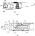
- Figure 3 is an illustrative perspective view of an optical fibre connector 300 suitable to be inserted into the fibre jumper end of the optical fibre adapter 100 of Figures 1 and 2
- Figure 4 is a cross section view of the assembled dust cap 200 and optical fibre adapter 100 of Figure 2 .
- an optical fibre connector dust cap is disclosed. As shown in Figures 1 and 2 , the dust cap is made of transparent material and suitable to fit within port 101 (the user end) of the optical fibre adapter 100, being for the purpose of preventing dust from entering the optical fibre adapter 100.
- an indicator lamp 112 is provided at port 101 of the optical fibre adapter 100 in the embodiment shown, being for the purpose of indicating the operational status of the optical fibre adapter.
- a reflective surface 212 is provided inside the dust cap 200.
- the dust cap 200 When the dust cap 200 is fitted within port 101 of the optical fibre adapter 100, and when the optical fibre connector 300 is inserted into the other port 102 of the optical fibre adapter 100, (i) light L1 emitted from the indicator lamp 112 hits one side of the reflective surface 212 (the left side in Figure 4 ), and is then reflected towards the external end section 230 of the dust cap 200 by the reflective surface 212, and is output from the external end section 230 of the dust cap 200; and (ii) laser L2 emitted from a fibre jumper optical fibre 330 in the optical fibre connector 300 hits the other side of the reflective surface 212 (the right side in Figure 4 ), and is then reflected towards the side section of the dust cap 200 by the reflective surface 212, and is output from the side section of the optical fibre adapter 100.
- the angle ⁇ between the reflective surface 212 and the axis of the optical fibre adapter 100 is larger than 0 degrees and less than 90 degrees.
- the angle ⁇ between the reflective surface 212 and the axis of the optical fibre adapter 100 is larger than 30 degrees and less than 60 degrees.
- the angle ⁇ between the reflective surface 212 and the axis of the optical fibre adapter 100 is equal to 45 degrees.
- the laser L2 emitted from the fibre jumper optical fibre 330 in the optical fibre connector 300 may be output to the exterior of the optical fibre adapter 100 in a direction perpendicular to the axis along the optical fibre adapter 100.
- optical fibre adapters 100 are generally densely installed in fibre junction boxes in rows. Thereby, only a very narrow gap is left at the sides of the optical fibre adapters 100. In this way, the operator can only see the indicator lamp on the optical fibre adapter 100 from the external end section of the dust cap 200 or the optical fibre adapter 100 when inserting or removing the optical fibre connectors 300.
- the light L1 emitted from the indicator lamp 112 is output from the external end section 230 of the dust cap 200, therefore, the operator may clearly see the operational status of the indicator lamp 112 at the external end section 230 of the dust cap 200.
- the laser L2 emitted from the fibre jumper optical fibre 330 in the optical fibre connector 300 is output from the side section of the optical fibre adapter 100, instead of being output from the external end section 230 of the dust cap 200, the operator cannot see the laser output from the side portion of the optical fibre adapter 100. In this way, operator eye injuries caused by the laser emitted from the fibre jumper optical fibre 330 are effectively prevented.
- the optical fibre connector 300 comprises a ferrule 320, the fibre jumper optical fibre 330 being retained by the ferrule 320.
- the external end section 230 of the dust cap 200 has a light output surface (may be referred to as a light output window) 230a, the light L1 emitted from the indicator lamp 112 being outputvia the light output surface 230a.
- the light output surface 230a is arranged perpendicular to the axis of the optical fibre adapter 100.
- the dust cap 200 has an insertion section 210 suitable to be inserted into and retained within port 101 of the optical fibre adapter 100.
- the reflective surface 212 is located within the insertion section 210 of the dust cap 200.
- a chamber 211 is formed within the bottom section of the insertion section 210 of the dust cap 200, and the reflective surface 212 constitutes an inclined wall surface of the chamber 211.
- the dust cap 200 has a flange 220 formed between the insertion section 210 and the external end section 230.
- the flange 220 abuts against the external end surface of port 101 of the optical fibre adapter 100, thereby improving the sealing of the optical fibre adapter 100.
- the indicator lamp 112 is an LED lamp.
- the indicator lamp 112 is provided on the bottom wall of the optical fibre adapter 100.
- an optical fibre connection assembly is disclosed. As shown in Figures 1 to 4 , the optical fibre connection assembly mainly comprises the optical fibre adapter 100, the above mentioned dust cap 200 and the optical fibre connector 300.
- the optical fibre adapter 100 has a first port 101 and a second port 102 opposite to the first port 101.
- An indicator lamp 112 is provided at the first port 101.
- the dust cap 200 is fitted within the first port 101 of the optical fibre adapter 100, and is for the purpose of sealing the first port 101.
- the optical fibre connector 300 is inserted into the second port 102 of the optical fibre adapter 100.
- an electronic chip 310 is provided within the optical fibre connector 300, said electronic chip 310 being provided to store information identifying the fibre jumper optical fibre 330.
- a signal reader 111 is provided on the optical fibre adapter 100, said signal reader 111 being for the purpose of reading the fibre jumper optical fibre 330 identification information stored in the electronic chip 310.
- the fibre jumper optical fibre 330 being read may be assigned to a specific user terminal, thus improving the efficiency of interconnection of the optical fibres, in addition to preventing connection of fibre jumper optical fibres 330 to incorrect user terminals.
- the signal reader 111 and the indicator lamp 112 are both mounted on the same circuit board 110; additionally, the circuit board 110 is mounted in the bottom section of the optical fibre adapter 100.
- the laser L2 emitted from the optical fibre connector 300 is reflected by the reflective surface 212 to a side-wall of the optical fibre adapter 100, instead of being output from the external end section 230 of the dust cap 200.
- the laser L2 emitted from the optical fibre connector 300 is prevented from causing operator eye injuries.
Landscapes
- Physics & Mathematics (AREA)
- General Physics & Mathematics (AREA)
- Optics & Photonics (AREA)
- Optical Couplings Of Light Guides (AREA)
- Mechanical Coupling Of Light Guides (AREA)
Applications Claiming Priority (2)
| Application Number | Priority Date | Filing Date | Title |
|---|---|---|---|
| CN201510119797.1A CN106033140B (zh) | 2015-03-18 | 2015-03-18 | 光纤适配器的防尘帽和光纤连接组件 |
| PCT/CN2016/076704 WO2016146081A1 (zh) | 2015-03-18 | 2016-03-18 | 光纤适配器的防尘帽和光纤连接组件 |
Publications (2)
| Publication Number | Publication Date |
|---|---|
| EP3285103A1 true EP3285103A1 (de) | 2018-02-21 |
| EP3285103A4 EP3285103A4 (de) | 2018-11-14 |
Family
ID=56918382
Family Applications (1)
| Application Number | Title | Priority Date | Filing Date |
|---|---|---|---|
| EP16764261.0A Withdrawn EP3285103A4 (de) | 2015-03-18 | 2016-03-18 | Staubdichte kappe eines glasfaseradapters und glasfaserverbindungsanordnung |
Country Status (4)
| Country | Link |
|---|---|
| US (1) | US10241276B2 (de) |
| EP (1) | EP3285103A4 (de) |
| CN (1) | CN106033140B (de) |
| WO (1) | WO2016146081A1 (de) |
Cited By (1)
| Publication number | Priority date | Publication date | Assignee | Title |
|---|---|---|---|---|
| CN110398805A (zh) * | 2019-07-30 | 2019-11-01 | 浙江申华电子科技有限公司 | 一种光纤适配器检测光提取装置以及sc光纤适配器 |
Families Citing this family (7)
| Publication number | Priority date | Publication date | Assignee | Title |
|---|---|---|---|---|
| JP1584768S (de) * | 2016-12-13 | 2017-08-28 | ||
| US10175427B2 (en) * | 2017-04-07 | 2019-01-08 | US Conec, Ltd | Low debris dust cap for MPO connectors |
| WO2019104273A1 (en) * | 2017-11-25 | 2019-05-31 | Smith Jack William | Dust and port idetification cap for fiber optic adapters |
| CN108614329B (zh) * | 2018-07-04 | 2024-04-05 | 南京华脉科技股份有限公司 | 一种适配器智能防尘帽 |
| CN113406753A (zh) * | 2021-06-30 | 2021-09-17 | 杭州精工技研有限公司 | 一种通光识别防尘帽 |
| US12700722B2 (en) * | 2022-03-18 | 2026-08-04 | Afl Telecommunications Llc | Quick-connect closure and handhole system |
| US12704686B1 (en) * | 2023-03-27 | 2026-08-11 | Senko Advanced Components, Inc. | Dust cap |
Family Cites Families (26)
| Publication number | Priority date | Publication date | Assignee | Title |
|---|---|---|---|---|
| JPH0833498B2 (ja) * | 1990-07-31 | 1996-03-29 | 富士通株式会社 | 通信装置の状態表示灯用受光アダプタ |
| US6227717B1 (en) | 1997-12-16 | 2001-05-08 | The Siemon Company | Dust caps for use with telecommunications adapters and connectors |
| US6188825B1 (en) | 1999-04-15 | 2001-02-13 | Lucent Technologies, Inc. | Dust cover for protecting optical fiber sleeve housing |
| US6554485B1 (en) | 2000-09-11 | 2003-04-29 | Corning Cable Systems Llc | Translucent dust cap and associated method for testing the continuity of an optical fiber jumper |
| AUPR245701A0 (en) | 2001-01-10 | 2001-02-01 | Silverbrook Research Pty Ltd | An apparatus (WSM10) |
| US6522806B1 (en) | 2001-02-16 | 2003-02-18 | Ethicon Endo-Surgury, Inc. | Optical fiber including a diffuser portion and continuous sleeve for the transmission of light |
| US20030002810A1 (en) | 2001-07-02 | 2003-01-02 | Yu-Feng Cheng | Illuminating optical fiber plug |
| US6634798B2 (en) | 2001-11-26 | 2003-10-21 | Yu-Feng Cheng | Illuminating dust proof cap for an optical fiber socket |
| CN2514361Y (zh) * | 2001-12-12 | 2002-10-02 | 伸金股份有限公司 | 光纤插座防尘盖 |
| JP2004094109A (ja) * | 2002-09-03 | 2004-03-25 | Furukawa Electric Co Ltd:The | 光コネクタ部品 |
| JP2004325522A (ja) * | 2003-04-21 | 2004-11-18 | Fujikura Ltd | 光コネクタ用キャップ |
| US7003198B2 (en) | 2003-09-09 | 2006-02-21 | Lucent Technologies Inc. | Integrateable band filter using waveguide grating routers |
| US7389024B2 (en) | 2003-10-09 | 2008-06-17 | Kilolambda Technologies Ltd. | Optical hot tip |
| US20050135772A1 (en) | 2003-12-19 | 2005-06-23 | Nield Scott A. | Optical fiber for a laser device having an improved tip diffuser and method of making same |
| US7164840B2 (en) | 2004-03-30 | 2007-01-16 | Finisar Corporation | Dust cap for fiber optic components |
| JP2006235502A (ja) * | 2005-02-28 | 2006-09-07 | Sanwa Denki Kogyo Co Ltd | 光プラグ用フェルールの保護キャップ |
| US7349619B2 (en) | 2005-05-25 | 2008-03-25 | Adc Telecommunications, Inc. | Fiber service blocker |
| US7329049B2 (en) | 2005-12-27 | 2008-02-12 | Corning Cable Systems Llc | Splice connector for verifying an acceptable splice termination |
| JP2007206584A (ja) | 2006-02-06 | 2007-08-16 | Hitachi Metals Ltd | 一方向性光パワーモニター |
| US7572066B2 (en) | 2006-03-14 | 2009-08-11 | Corning Cable Systems Llc | Translucent dust cap for fiber optic adapter |
| US7565053B2 (en) | 2007-06-05 | 2009-07-21 | Adc Telecommunications, Inc. | Fiber optic dust cap and dust plug with high power protection |
| US7945139B2 (en) * | 2007-06-13 | 2011-05-17 | Corning Cable Systems Llc | Dust cap for fiber optic adapter |
| CN201673299U (zh) * | 2010-06-01 | 2010-12-15 | 江苏省邮电规划设计院有限责任公司 | 一种具有智能光纤管理和标识功能的光纤配线装置 |
| CN201812056U (zh) * | 2010-08-09 | 2011-04-27 | 吴小荣 | 光纤适配器 |
| US8734024B2 (en) * | 2011-11-28 | 2014-05-27 | Corning Cable Systems Llc | Optical couplings having a coded magnetic array, and connector assemblies and electronic devices having the same |
| TW201339679A (zh) * | 2012-03-22 | 2013-10-01 | Hon Hai Prec Ind Co Ltd | 光電轉換器 |
-
2015
- 2015-03-18 CN CN201510119797.1A patent/CN106033140B/zh not_active Expired - Fee Related
-
2016
- 2016-03-18 EP EP16764261.0A patent/EP3285103A4/de not_active Withdrawn
- 2016-03-18 WO PCT/CN2016/076704 patent/WO2016146081A1/zh not_active Ceased
- 2016-03-18 US US15/559,303 patent/US10241276B2/en active Active
Cited By (1)
| Publication number | Priority date | Publication date | Assignee | Title |
|---|---|---|---|---|
| CN110398805A (zh) * | 2019-07-30 | 2019-11-01 | 浙江申华电子科技有限公司 | 一种光纤适配器检测光提取装置以及sc光纤适配器 |
Also Published As
| Publication number | Publication date |
|---|---|
| EP3285103A4 (de) | 2018-11-14 |
| CN106033140B (zh) | 2018-04-27 |
| WO2016146081A1 (zh) | 2016-09-22 |
| US10241276B2 (en) | 2019-03-26 |
| US20180196201A1 (en) | 2018-07-12 |
| CN106033140A (zh) | 2016-10-19 |
Similar Documents
| Publication | Publication Date | Title |
|---|---|---|
| US10241276B2 (en) | Dustproof cap of optical fiber adapter, and optical fiber connection assembly | |
| US10215928B2 (en) | Unitary fiber optic ferrule and adapter therefor | |
| AU2013100899B4 (en) | Female hardened optical connectors for use with male plug connectors | |
| US8314603B2 (en) | Network cable with tracer optical waveguide | |
| US9791639B2 (en) | Optical fiber connector assembly, optical fiber connector plug, and adapter assembly | |
| CN1133886C (zh) | 光纤连接器的适配组件 | |
| CN212569204U (zh) | 光学连接器和光学连接器组件 | |
| US9002170B2 (en) | Dust cap for fiber optic cable or adapter | |
| AU2016354003A1 (en) | Bladed chassis systems and removable cassettes | |
| EP0945933B1 (de) | Moduläre Steckerbuchsenanordnung mit Anzeigenleuchte | |
| CN111213150A (zh) | 光纤连接器组件 | |
| US11874507B2 (en) | Dust cap for fiber optic adapters | |
| WO2018066581A1 (ja) | 導光部品、プラグ、及びアダプター | |
| CN107250864B (zh) | 光纤电缆组件及测定装置 | |
| TW201447410A (zh) | 光纖耦合連接器 | |
| KR101410495B1 (ko) | 광커넥터 접속용 어댑터의 더스트 캡 | |
| US20180267262A1 (en) | Optical connector attachment tool having light transmissive wedge | |
| CN211061735U (zh) | 一种光纤适配器及其光路侧向显示器 | |
| CN105824082B (zh) | 一种跳纤 | |
| US8602659B2 (en) | Optical fiber connector | |
| CN209911602U (zh) | 一种光纤适配器 | |
| US9870680B2 (en) | Communication light visualization structure | |
| US20240151914A1 (en) | Dust and port identification cap for fiber optic adapters | |
| US20130071069A1 (en) | Optical fiber connector | |
| EP4632454A1 (de) | Mit verbinder ausgestattetes glasfaserkabel und optisches übertragungssystem |
Legal Events
| Date | Code | Title | Description |
|---|---|---|---|
| STAA | Information on the status of an ep patent application or granted ep patent |
Free format text: STATUS: THE INTERNATIONAL PUBLICATION HAS BEEN MADE |
|
| PUAI | Public reference made under article 153(3) epc to a published international application that has entered the european phase |
Free format text: ORIGINAL CODE: 0009012 |
|
| STAA | Information on the status of an ep patent application or granted ep patent |
Free format text: STATUS: THE APPLICATION HAS BEEN PUBLISHED |
|
| STAA | Information on the status of an ep patent application or granted ep patent |
Free format text: STATUS: REQUEST FOR EXAMINATION WAS MADE |
|
| 17P | Request for examination filed |
Effective date: 20171017 |
|
| AK | Designated contracting states |
Kind code of ref document: A1 Designated state(s): AL AT BE BG CH CY CZ DE DK EE ES FI FR GB GR HR HU IE IS IT LI LT LU LV MC MK MT NL NO PL PT RO RS SE SI SK SM TR |
|
| AX | Request for extension of the european patent |
Extension state: BA ME |
|
| DAV | Request for validation of the european patent (deleted) | ||
| DAX | Request for extension of the european patent (deleted) | ||
| A4 | Supplementary search report drawn up and despatched |
Effective date: 20181017 |
|
| RIC1 | Information provided on ipc code assigned before grant |
Ipc: G02B 6/36 20060101ALI20181010BHEP Ipc: G02B 6/38 20060101AFI20181010BHEP |
|
| STAA | Information on the status of an ep patent application or granted ep patent |
Free format text: STATUS: THE APPLICATION HAS BEEN WITHDRAWN |
|
| 18W | Application withdrawn |
Effective date: 20190722 |