EP3285200A1 - Lesevorrichtung und steuerungsprogramm für lesevorrichtung - Google Patents
Lesevorrichtung und steuerungsprogramm für lesevorrichtung Download PDFInfo
- Publication number
- EP3285200A1 EP3285200A1 EP17186859.9A EP17186859A EP3285200A1 EP 3285200 A1 EP3285200 A1 EP 3285200A1 EP 17186859 A EP17186859 A EP 17186859A EP 3285200 A1 EP3285200 A1 EP 3285200A1
- Authority
- EP
- European Patent Office
- Prior art keywords
- antenna
- tag
- reading
- rotate
- controller
- Prior art date
- Legal status (The legal status is an assumption and is not a legal conclusion. Google has not performed a legal analysis and makes no representation as to the accuracy of the status listed.)
- Withdrawn
Links
Images




Classifications
-
- G—PHYSICS
- G06—COMPUTING OR CALCULATING; COUNTING
- G06K—GRAPHICAL DATA READING; PRESENTATION OF DATA; RECORD CARRIERS; HANDLING RECORD CARRIERS
- G06K7/00—Methods or arrangements for sensing record carriers, e.g. for reading patterns
- G06K7/10—Methods or arrangements for sensing record carriers, e.g. for reading patterns by electromagnetic radiation, e.g. optical sensing; by corpuscular radiation
- G06K7/10009—Methods or arrangements for sensing record carriers, e.g. for reading patterns by electromagnetic radiation, e.g. optical sensing; by corpuscular radiation sensing by radiation using wavelengths larger than 0.1 mm, e.g. radio-waves or microwaves
- G06K7/10316—Methods or arrangements for sensing record carriers, e.g. for reading patterns by electromagnetic radiation, e.g. optical sensing; by corpuscular radiation sensing by radiation using wavelengths larger than 0.1 mm, e.g. radio-waves or microwaves using at least one antenna particularly designed for interrogating the wireless record carriers
-
- G—PHYSICS
- G06—COMPUTING OR CALCULATING; COUNTING
- G06K—GRAPHICAL DATA READING; PRESENTATION OF DATA; RECORD CARRIERS; HANDLING RECORD CARRIERS
- G06K7/00—Methods or arrangements for sensing record carriers, e.g. for reading patterns
- G06K7/10—Methods or arrangements for sensing record carriers, e.g. for reading patterns by electromagnetic radiation, e.g. optical sensing; by corpuscular radiation
- G06K7/10009—Methods or arrangements for sensing record carriers, e.g. for reading patterns by electromagnetic radiation, e.g. optical sensing; by corpuscular radiation sensing by radiation using wavelengths larger than 0.1 mm, e.g. radio-waves or microwaves
-
- G—PHYSICS
- G06—COMPUTING OR CALCULATING; COUNTING
- G06K—GRAPHICAL DATA READING; PRESENTATION OF DATA; RECORD CARRIERS; HANDLING RECORD CARRIERS
- G06K7/00—Methods or arrangements for sensing record carriers, e.g. for reading patterns
- G06K7/10—Methods or arrangements for sensing record carriers, e.g. for reading patterns by electromagnetic radiation, e.g. optical sensing; by corpuscular radiation
- G06K7/10009—Methods or arrangements for sensing record carriers, e.g. for reading patterns by electromagnetic radiation, e.g. optical sensing; by corpuscular radiation sensing by radiation using wavelengths larger than 0.1 mm, e.g. radio-waves or microwaves
- G06K7/10019—Methods or arrangements for sensing record carriers, e.g. for reading patterns by electromagnetic radiation, e.g. optical sensing; by corpuscular radiation sensing by radiation using wavelengths larger than 0.1 mm, e.g. radio-waves or microwaves resolving collision on the communication channels between simultaneously or concurrently interrogated record carriers.
- G06K7/10079—Methods or arrangements for sensing record carriers, e.g. for reading patterns by electromagnetic radiation, e.g. optical sensing; by corpuscular radiation sensing by radiation using wavelengths larger than 0.1 mm, e.g. radio-waves or microwaves resolving collision on the communication channels between simultaneously or concurrently interrogated record carriers. the collision being resolved in the spatial domain, e.g. temporary shields for blindfolding the interrogator in specific directions
- G06K7/10089—Methods or arrangements for sensing record carriers, e.g. for reading patterns by electromagnetic radiation, e.g. optical sensing; by corpuscular radiation sensing by radiation using wavelengths larger than 0.1 mm, e.g. radio-waves or microwaves resolving collision on the communication channels between simultaneously or concurrently interrogated record carriers. the collision being resolved in the spatial domain, e.g. temporary shields for blindfolding the interrogator in specific directions the interrogation device using at least one directional antenna or directional interrogation field to resolve the collision
-
- G—PHYSICS
- G06—COMPUTING OR CALCULATING; COUNTING
- G06K—GRAPHICAL DATA READING; PRESENTATION OF DATA; RECORD CARRIERS; HANDLING RECORD CARRIERS
- G06K7/00—Methods or arrangements for sensing record carriers, e.g. for reading patterns
- G06K7/10—Methods or arrangements for sensing record carriers, e.g. for reading patterns by electromagnetic radiation, e.g. optical sensing; by corpuscular radiation
- G06K7/10009—Methods or arrangements for sensing record carriers, e.g. for reading patterns by electromagnetic radiation, e.g. optical sensing; by corpuscular radiation sensing by radiation using wavelengths larger than 0.1 mm, e.g. radio-waves or microwaves
- G06K7/10366—Methods or arrangements for sensing record carriers, e.g. for reading patterns by electromagnetic radiation, e.g. optical sensing; by corpuscular radiation sensing by radiation using wavelengths larger than 0.1 mm, e.g. radio-waves or microwaves the interrogation device being adapted for miscellaneous applications
- G06K7/10415—Methods or arrangements for sensing record carriers, e.g. for reading patterns by electromagnetic radiation, e.g. optical sensing; by corpuscular radiation sensing by radiation using wavelengths larger than 0.1 mm, e.g. radio-waves or microwaves the interrogation device being adapted for miscellaneous applications the interrogation device being fixed in its position, such as an access control device for reading wireless access cards, or a wireless ATM
- G06K7/10425—Methods or arrangements for sensing record carriers, e.g. for reading patterns by electromagnetic radiation, e.g. optical sensing; by corpuscular radiation sensing by radiation using wavelengths larger than 0.1 mm, e.g. radio-waves or microwaves the interrogation device being adapted for miscellaneous applications the interrogation device being fixed in its position, such as an access control device for reading wireless access cards, or a wireless ATM the interrogation device being arranged for interrogation of record carriers passing by the interrogation device
Definitions
- the present invention relates to a tag reading technology in general, and embodiments described herein relate in particular to a reading device and a control program for a reading device.
- RFID Radio Frequency Identification
- the RFID tags store information regarding the merchandise or the inventory and this stored information can be read from the tag using a reading device.
- the tag reading process can read a plurality of RFID tags at the same time, or substantially so, to improve the efficiency of the merchandise or inventory management process.
- a reading device which can read a plurality of RFID tags at once, it is also desirable to prevent failures in the reading of the RFID tags so as to improve efficiency of the reading process.
- a reading device comprising:
- the stages moves the antenna from a first position to a second position and from the second position to the first position, rotates the antenna by a predetermined amount when the antenna is at the second position after being moved from the first position, and rotates the antenna by the predetermined amount when the antenna is at the first position after being moved from the second position, and the tag reader supplies signals to the antenna for reading information from the wireless tag while the antenna is traversing between the first and second positions.
- the predetermined amount is preferably 30°.
- the stage moves the antenna from a first position to a second position and from the second position to the first position, rotates the antenna by a predetermined amount while the antenna traversing from the first position to second position, and rotates the antenna by the predetermined amount while the antenna traversing from the second position to the first position, and the tag reader supplies signals to the antenna for reading information from the wireless tag while the antenna is traversing between the first and second positions.
- the predetermined amount is preferably 30°.
- the antenna is a planar patch antenna.
- the wireless tag is preferably an RFID tag.
- the invention also relates to a tag reading apparatus, comprising:
- the tag reading apparatus further comprises a controller configured to:
- the controller causes the rotational movement mechanism to rotate the antenna about the axis by the predetermined amount when the antenna is at the second position during the tag reading process.
- the controller causes the rotational movement mechanism to rotate the antenna about the axis by the predetermined amount while the linear movement mechanism is moving the antenna along the second direction between the first position and the second position during the tag reading process.
- the controller causes the rotational movement mechanism to rotate a total of 90° about the axis from an initial position during the tag reading process.
- the predetermined amount is preferably 30°.
- the tag reading apparatus further comprises:
- the wireless tag is preferably an RFID tag.
- the antenna is a planar patch antenna.
- the invention further concerns a non-transitory computer readable medium storing program instructions that when executed by a wireless tag reading device causes:
- the program instructions when executed further cause:
- program instructions when executed further cause:
- the antenna is a planar patch antenna.
- a reading device includes an antenna having a signal radiating surface and configured to output a linearly polarized wave from the radiating surface, a movable and rotatable stage supporting the antenna and configured to move the antenna along a first direction parallel to the radiating surface of the antenna and rotate the antenna on an axis that is normal to the radiating surface of the antenna, and a tag reader connected to the antenna and configured to supply signals to the antenna for reading information from a wireless tag and to receive signals from the antenna including information read from the wireless tag.
- FIG. 1 is an exterior perspective view of a check-out counter 10 in which a reading device 2 is installed.
- a point-of-sale (POS) terminal 1 is a merchandise sales data processing device (e.g., a cash register or the like) which is installed in a store such as a supermarket or the like and used for registration and settlement processing of merchandise being purchased by a customer.
- the reading device 2 reads information of an RFID tag that is attached to merchandise. The reading is performed in a non-contact manner using radio waves.
- the POS terminal 1 includes a main body 11, a salesperson side display 3, a customer side display 4, a keyboard 5, a bar-code reader 6, a card reader 7, a receipt printer 8, and a drawer 9.
- the POS terminal 1 is connected to the reading device 2.
- the main body 11 includes the salesperson side display 3, the customer side display 4, the keyboard 5, the bar-code reader 6, the card reader 7, the receipt printer 8, and the drawer 9.
- the salesperson side display 3 is attached to an upper part of the main body 11 towards an inside (salesperson side) of the check-out counter 10.
- the salesperson side display 3 displays information such as a name, a price, or the like of the merchandise corresponding to a commodity code input into the POS terminal 1.
- the salesperson side display 3 may have a function of a touch panel capable of recognizing an instruction by a salesperson's pressing of keys or buttons.
- the customer side display 4 is attached to an outside (customer side) of the check-out counter 10 while facing a back surface to the salesperson side display 3.
- the keyboard 5 includes a key such as a closing key for declaring an end of sales registration processing of merchandise M being purchased by a customer.
- the bar-code reader 6 reads information such as a merchandise code or the like from a bar-code that is attached to the merchandise M.
- the card reader 7 reads information of customer's points card (e.g., a customer loyalty card) or a credit card inserted in a card insertion slot (not specifically illustrated in Fig. 1 ).
- the receipt printer 8 prints a receipt after an accounting process and issues the receipt from a receipt issue opening (not specifically illustrated in Fig. 1 ).
- the drawer 9 includes a drawer capable of opening and closing and accommodates cash or the like in the drawer.
- a controller 26 housed inside the main body 11 is connected to a store controller, such as a server or the like, which has a merchandise database.
- the POS terminal 1 queries the store controller for information associated with a merchandise code read by the bar-code reader 6 or a merchandise code read by the reading device 2 and can thus obtain merchandise information such as a merchandise name, a merchandise image, and a merchandise unit price corresponding to the merchandise code.
- the POS terminal 1 performs sales registration processing of the merchandise using the merchandise information.
- the wireless tag is an RFID tag operating in an UHF band.
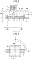
- Fig. 2 is a side view (viewed along the arrow A in Fig. 1 ) illustrating a schematic configuration of the reading device 2.
- the reading device 2 can be installed inside the check-out counter 10.
- the reading device 2 may be embedded in the check-out counter 10 or may be placed in a drawer or on a shelf board, or the like of the check-out counter 10.
- a top board of the check-out counter 10 is made of a material through which radio waves penetrate and may be made of, for example, a wooden material.
- the customer may directly place the merchandise M to be purchased on the top board of the check-out counter 10.
- the customer may place a shopping basket containing the merchandise M on the top board of the check-out counter 10.
- An RFID tag T that is attached to the merchandise M stores unique identification information and other information such as a merchandise code or the like corresponding to the merchandise M to which the RFID tag T is attached.
- the reading device 2 reads tag information such as tag identification information, the merchandise code, and the like from the RFID tag T attached to the merchandise M and then transmits the read tag information to the POS terminal 1.
- the reading device 2 includes an RFID antenna 22 of a linearly polarized wave type. As indicated by the upward arrow in Fig. 2 , the antenna 22 is provided so that a traveling direction of a linearly polarized RFID radio wave emitted from the antenna 22 is directed to the top board of the check-out counter 10.
- the antenna 22 of RFID is attached to a rotation axis 222 of a stepping motor 13.
- the upward arrow in Fig. 2 is a traveling direction of a linearly polarized wave of RFID.
- the antenna 22 is rotatable about an axis parallel to the traveling direction of the linearly polarized wave.
- the stepping motor 13 is provided on a moving stage 20 horizontally (in a direction perpendicular to the traveling direction of the linearly polarized wave) moved by a moving mechanism 24.
- the antenna 22 on the stepping motor 13 reads the RFID tag while moving in the directions indicated by the arrows M1 and M2 in Fig. 2 .
- the reading device 2 changes a polarization direction of a linearly polarized RFID wave by rotating an antenna surface of the antenna 22. Accordingly, tag information can be read regardless of an orientation of the RFID tag T on the check-out counter 10 and failure to read the RFID tag can be prevented. That is, by adopting the rotatable antenna 22 of the linearly polarized wave type, a reading area with higher electric field intensity for RFID communication can be expanded as compared to an RFID antenna of a circularly polarized wave type. Therefore, information communication efficiency and reading accuracy are improved with antenna 22. Furthermore, due to the rotation of the antenna 22 around the traveling direction of a radio wave, reading of tag information can still be performed without failure to read RFID tags of various orientations with respect to the antenna in substantially the same manner as with a circularly polarized wave type antenna.
- Fig. 3 is a diagram illustrating a schematic configuration of the rotation mechanism of the antenna 22.
- the stepping motor 13 is attached to an upper surface of the moving stage 20.
- the antenna 22 is fixed to the rotation axis 222 of the stepping motor 13 and rotated in a clockwise direction or in a counterclockwise direction together with rotation of the rotation axis 222.
- the moving stage 20 has a through hole, and a screw shaft 18 is fitted in the through hole as illustrated in Fig. 2 . This configuration will be described below in explanation of the moving mechanism 24.
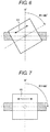
- Figs. 4 to 7 are explanatory diagrams illustrating rotation operations of the antenna 22.
- Fig. 4 illustrates an initial state related to a rotation angle of the antenna 22. In this state, assuming that a rotation angle R1 is 0°, the antenna 22 is subsequently rotated in a clockwise direction, the rotation angle R1 is 30° as illustrated in Fig. 5 , the rotation angle R1 is 60° as illustrated in Fig. 6 , and then the rotation angle R1 becomes 90° as illustrated in Fig. 7 .
- a polarization direction H1 of a linearly polarized wave is also rotated together with the rotation angle R1 of the antenna 22.
- an antenna of a linearly polarized wave type can have a wider reading area with higher electric field intensity.
- a rotatable antenna 22 by rotating the antenna 22 of the linearly polarized wave type by the rotation mechanism, the reading device 2 combines advantages of the antenna of the linearly polarized wave type and advantages of the antenna of the circularly polarized wave type.
- the reading device 2 includes the moving mechanism 24 which allows the antenna 22 to move along the top board of the check-out counter 10.
- the moving mechanism 24 is a mechanism for moving the antenna 22 in parallel with the antenna surface.
- the moving mechanism 24 includes a linear motion mechanism having the screw shaft 18, a bearing 16 of the screw shaft 18, a stepping motor 12, a coupling 14, and the moving stage 20.
- the stepping motor 12 is a rotational power source.
- the coupling 14 transmits rotational power of the stepping motor 12 to the screw shaft 18.
- the moving stage 20 is integrally configured with a ball screw nut screwed to the screw shaft 18.
- One end of the screw shaft 18 is horizontally supported by the bearing 16 and the other end of the screw shaft 18 is horizontally supported by the coupling 14.
- the screw shaft 18 so installed is thus axially-rotatable.
- an output shaft 12a of the stepping motor 12 is connected with the other end of the screw shaft 18 in the coupling 14. With this configuration, rotation power of the stepping motor 12 is transmitted from the output shaft 12a to the screw shaft 18 via the coupling 14.
- the moving stage 20 has a through hole and the ball screw nut of the screw shaft 18 is embedded in the through hole.
- the moving stage 20 moves forward and backward along the screw shaft 18 together with rotation of the screw shaft 18, that is, moves in the directions of the arrow M1 and the arrow M2 in Fig. 2 . Since a metallic ball (e.g., steel ball) is interposed in a threaded unit between the screw shaft 18 and the ball screw nut, the moving stage 20 can be moved smoothly.
- the moving mechanism 24 changes a rotational motion of the stepping motor 12 to a linear motion by a mechanism of the ball screw described above, so that the moving stage 20 can move forward and backward.
- the moving stage 20 is moved while keeping a part of the moving stage 20 in contact with a supporting plate 21.
- the moving stage 20 so installed is not to rotate as the screw shaft 18 rotates. Accordingly, the moving stage 20 is moved without rotating.
- the antenna 22 On an upper surface of the moving stage 20, the antenna 22 is fixed so that a reading surface of the antenna 22 is facing the top board of the check-out counter 10.
- the reading surface of the antenna 22 refers to a radiation surface from which a planar patch antenna emits a radio wave. According to this disposition, the antenna 22 emits a radio wave towards the reading surface, that is, toward the top board of the check-out counter 10. Then, the antenna 22 is moved along the screw shaft 18 integrally with the moving stage 20.
- the moving stage 20 moves on the screw shaft 18 in a direction of the arrow M2 in Fig. 2 .
- the moving stage 20 moves on the screw shaft 18 in a direction of the arrow M1 in Fig. 2 .
- the antenna 22 integrally moves with the moving stage 20 so that a reading surface of the antenna 22 is facing upward (in a direction of the top board of the check-out counter 10). With this movement, the antenna 22 communicates with the RFID tag T while changing a range of communication with the RFID tag T.
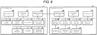
- FIG. 8 is a block diagram illustrating hardware aspects of the POS terminal 1 and the reading device 2.
- the POS terminal 1 includes the controller 26 having a Central Processing Unit (CPU), a Read Only Memory (ROM), a Random Access Memory (RAM), and the like.
- CPU Central Processing Unit
- ROM Read Only Memory
- RAM Random Access Memory
- ROM stores various programs executed by CPU and various types of data.
- RAM temporarily stores data or programs when CPU executes various programs.
- the salesperson side display 3, the customer side display 4, the keyboard 5, the bar-code reader 6, the card reader 7, the drawer 9, and the receipt printer 8 are connected to the controller 26 via various input/output (I/O) circuits (not specifically illustrated).
- I/O input/output
- a storage unit 27 and a communication I/F 28 are connected to the controller 26 via various input/output circuits.
- the storage unit 27 is a storage device including a nonvolatile storage medium, such as a Hard Disk Drive (HDD) or a Solid State Drive (SSD).
- the storage unit 27 stores various programs or various types of data related to an operation of the POS terminal 1.
- data stored in the storage unit 27 there is, for example, a merchandise master list in which merchandise information related to each piece of merchandise has been registered in association with a merchandise code for identifying the merchandise.
- Relevant merchandise information includes, for example, a merchandise name, a price, and the like of the corresponding merchandise.
- the communication I/F 28 is an interface for performing transmission and reception of various types of data to and from the reading device 2.
- the reading device 2 includes a controller 32 having CPU, ROM, RAM, and the like.
- ROM stores various programs executed by CPU and various types of data.
- RAM temporarily stores data or programs when CPU executes various programs.
- a storage unit 34 a communication I/F 36, a reader/writer 38, a motor driver 40, a motor driver 41, a position sensor 42, and the like are connected to the controller 32 via various input/output (I/O) circuits.
- I/O input/output
- the reader/writer 38 and the antenna 22 can be connected with each other using a flexible coaxial cable.
- the reader/writer 38 communicates with the RFID tag T and performs transmission and reception of data through the antenna 22 under the instruction from the controller 32.
- the reader/writer 38 can be referred to as a tag reader.
- the storage unit 34 is a storage device including a nonvolatile storage medium such as HDD or SSD.
- the storage unit 34 stores various programs or various types of data related to an operation of the reading device 2.
- the communication I/F 36 is an interface for performing transmission and reception of various types of data to and from the POS terminal 1.
- the motor driver 40 is a driver circuit for operating the stepping motor 12.
- the motor driver 40 outputs a pulse signal for rotating the stepping motor 12 by a predetermined angle based on an instruction of the controller 32.
- the motor driver 41 is a driver circuit for operating the stepping motor 13.
- the motor driver 41 outputs a pulse signal for rotating the stepping motor 13 by a predetermined angle based on an instruction of the controller 32.
- the position sensor 42 is a sensor for improving positioning accuracy of the moving stage 20 and for example, a micro switch, a proximity sensor, or the like can be used.
- the position sensor 42 detects that the moving stage 20 is at the point B (e.g., a start position) in Fig. 2 or at the point C (e.g., an end position) in Fig. 2 .
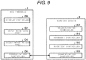
- FIG. 9 is a block diagram illustrating the functional aspects of the POS terminal 1 and the reading device 2.
- CPU of the controller 26 of the POS terminal 1 functions as a display controller 100, an input receiving unit 102, a sales registration unit 104, and a communication controller 106 by executing programs saved in the storage unit 27.
- the display controller 100 controls the salesperson side display 3 and displays various screens on the salesperson side display 3. For example, the display controller 100 generates a screen having a button, an icon, or the like (hereinafter, referred to as "reading start button”) for instructing the start of the reading the merchandise code or a button, an icon, or the like (hereinafter, referred to as "reading end button”) for instructing the end of the reading.
- the display controller 100 reads merchandise information corresponding to the merchandise code from a merchandise master list and carries out a process to display a merchandise name, a price, tendered amount, change due amount, and the like of the merchandise M on the salesperson side display 3.
- the display controller 100 controls the customer side display 4 and displays various screens on the customer side display 4. For example, based on a merchandise code transmitted from the reading device 2, the display controller 100 carries out a process to display a merchandise name, a price, and the like of the merchandise M being purchased by a customer on both the salesperson side display 3 and the customer side display 4.
- the input receiving unit 102 receives an input via the keyboard 5 or a touch panel. For example, when the button or key is pressed on an operation screen displayed on the salesperson side display 3, the input receiving unit 102 outputs instruction information corresponding to the pressed button or key to the controller 26.
- the sales registration unit 104 When the payment is confirmed upon settlement with respect to each piece of merchandise corresponding to a merchandise code transmitted from the reading device 2, the sales registration unit 104 performs sales registration the merchandise being purchased by a customer. Specifically, the sales registration unit 104 registers the merchandise code of each piece of merchandise together with a tendered amount, change due, transaction date and time in a database for registration.
- the database for registration may be included in the storage unit 27 of the POS terminal 1 or in an external device capable of communicating with the POS terminal 1.
- the communication controller 106 transmits and receives various types of information to and from the reading device 2 via the communication I/F 28. For example, if the reading start button is pressed, the communication controller 106 transmits instruction information for instructing a reading start to the reading device 2. In addition, the communication controller 106 receives a merchandise code transmitted from the reading device 2. In addition, if the reading end button is pressed, the communication controller 106 transmits instruction information for instructing a reading end to the reading device 2.
- the controller 32 (CPU) of the reading device 2 functions as a reader/writer controller 112, a movement controller 114, a rotation controller 116, and a communication controller 118 by cooperating with a program saved in the storage unit 34.
- the reader/writer controller 112 performs a reading from the RFID tag attached to merchandise and writing to the RFID tag via the antenna 22 by controlling the reader/writer 38 (see Fig. 8 ).
- the reader/writer controller 112 starts reading of the RFID tag.
- the reader/writer controller 112 reads tag information saved in the RFID tag by receiving a reflected wave of a radio wave emitted from the antenna 22.
- the reader/writer controller 112 transmits the tag information read from the RFID tag to the POS terminal 1 at any time during or after the reading.
- the reader/writer controller 112 ends the reading by the reader/writer 38. If the end of the registration has been instructed from the POS terminal 1, the reader/writer controller 112 controls the reader/writer 38 and writes a registration end flag to the RFID tag.
- the registration end flag is information indicating an end of sales registration for the particular RFID tag and is written to a predetermined storage area of each RFID tag.
- the movement controller 114 controls an operation of the stepping motor 12 via the motor driver 40 and controls a movement of the moving stage 20, that is, a movement of the antenna 22. More specifically, the movement controller 114 controls the stepping motor 12 to rotate in a direction by a predetermined number of pulses to move the moving stage 20 from the point B to the point C in Fig. 2 . The predetermined number of pulses may appropriately be set according to a pitch or the like of a screw formed on the stepping motor 12 and the screw shaft 18. In addition, the movement controller 114 controls the stepping motor 12 to rotate in a reverse direction to move the moving stage 20 from the point C to the point B in Fig. 2 .
- the movement controller 114 monitors an output of the position sensor 42 and detects that the moving stage 20 reaches the point B or the point C. For example, when the moving stage 20 is reciprocated between the point B and the point C, if the position sensor 42 detects that the moving stage 20 reaches the point B, the movement controller 114 switches a rotation direction of the stepping motor 12 from a normal direction to a reverse direction. The movement controller 114 controls movement of the moving stage 20 from the point C to the point B. For two reciprocating cycles, this operation is repeated twice. Other examples of a movement pattern will be described below with a flowchart.
- the movement controller 114 controls movement of the moving stage 20 to the point B, which is a home position.
- the rotation controller 116 controls an operation of the stepping motor 13 via the motor driver 41 and rotates the antenna 22 in a clockwise direction or in a counterclockwise direction. More specifically, the rotation controller 116 outputs a rotation angle and a rotation direction of the antenna 22 to the motor driver 41, and the motor driver 41 rotates and moves the stepping motor 13 by the number of steps in accordance with the rotation angle.
- the rotation controller 116 controls the rotation and movement of the antenna 22 at a predetermined timing by cooperating with the movement controller 114.
- a timing of rotation for example, the rotation controller 116 performs a rotation operation of the antenna 22 when the antenna 22 reaches the point B or the point C.
- the rotation controller 116 performs a rotation operation of the antenna 22 while the antenna 22 is moved from the point B to the point C.
- the rotation controller 116 returns the rotation angle R1 (see Fig. 3 ) of the antenna 22 to 0°, which is an initial state, and ends the rotation operation.
- a timing at which the rotation angle is 0° may be set while the antenna 22 is moved to the point B, which is the home position, or after a movement of the antenna 22 to the point B has been completed.
- the communication controller 118 transmits and receives various types of information to and from the POS terminal 1 via the communication I/F 36. For example, the communication controller 118 receives instruction information for instructing a reading start received from the POS terminal 1. In addition, the communication controller 118 receives instruction information for instructing a reading end received from the POS terminal 1. In addition, the communication controller 118 transmits a merchandise code read from the RFID tag by the reader/writer controller 112 to the POS terminal 1. In this manner, the reader/writer controller 112 and the communication controller 118 function as an information output unit which reads information from the RFID tag via the antenna 22 and outputs the information.
- FIG. 10 is a flowchart illustrating a procedural example of a reading process for reading information from the RFID tag performed by the POS terminal 1 and the reading device 2.
- the reading start may be instructed from the button or key displayed on the salesperson side display 3 including a touch panel function instead of the keyboard 5.
- the input receiving unit 102 of the POS terminal 1 receives a reading start instruction of the RFID tag by receiving the pressed button or key (step S1).
- the reader/writer controller 112 of the reading device 2 instructs a reading start to the reader/writer 38 and starts a reading process of the RFID tag (step S11).
- the movement controller 114 starts reciprocating movement control of the antenna 22 and the rotation controller 116 starts rotation driving control of the antenna 22 at a beginning of the reading process (step S11).
- a procedural example of reciprocating movement control and rotation driving control will be described below with reference to Fig. 11 and the following Figs.
- step S12 If the reader/writer controller 112 reads tag information from the RFID tag (Yes in step S12), the communication controller 118 transmits the read tag information to the POS terminal 1 at any time during or after the reading (step S 13). If tag information is not read (No in step S12), the reading process is continued together with a movement operation and a rotation operation of the moving stage 20 and the process is moved to step S14.
- step S2 If tag information is received from the reading device 2 (step S2), the communication controller 106 of the POS terminal 1 reads merchandise information corresponding to a merchandise code included in the tag information from a merchandise master list.
- the display controller 100 carries out a process to display the merchandise information that has been read on the salesperson side display 3 and the customer side display 4 (step S3).
- the display controller 100 determines whether or not the newly read tag information overlaps with the tag information that has already been read based on tag identification information and displays a reading result to avoid displaying inadvertently repeated reading results. Overlapping information may be excluded on the POS terminal 1 side. Alternatively, a reading result may be transmitted to the POS terminal 1 only after excluding the overlapping information on the reading device 2 side.
- step S4 When a salesperson determines that reading of the RFID tags for all of merchandise has been completed and merchandise information is correctly displayed on the salesperson side display 3, the salesperson presses the reading end button. If the input receiving unit 102 receives the instruction of the reading end button being pressed (Yes in step S4), the communication controller 106 transmits instruction information for instructing a reading end to the reading device 2 (step S5). While the reading end button is not pressed (No in step S4), the process returns to step S2.
- the reader/writer controller 112 stops the reading process of the RFID tags (step S15).
- the movement controller 114 stops reciprocating movement control of the antenna 22 and the rotation controller 116 stops rotation driving control of the antenna 22 (step S15). That is, the movement controller 114 stops a movement of the moving stage 20, returns the moving stage 20 to the point B, which is the home position, and stops driving of the stepping motor 12.
- the rotation controller 116 stops rotational driving of the antenna 22, sets the rotation angle R1 of the antenna 22 to 0°, and stops driving of the stepping motor 13.
- step S 14 If the instruction information for instructing a reading end is not yet received (No in step S 14), the process returns to step S12.
- the sales registration unit 104 of the POS terminal 1 performs settlement processing by calculating a deposit, a change due amount, and the like according to a selection operation of a transaction end key or the like (step S6). If the settlement processing is ended, the sales registration unit 104 registers the merchandise to a journal or the like for record keeping and the communication controller 106 transmits instruction information for instructing a registration end to the reading device 2 (step S7) and ends the process.
- the reader/writer controller 112 controls the reader/writer 38, writes a registration end flag to all of the RFID tag (step S17), and stops the processing. While the instruction information is not received (No in step S16), the process waits to receive the instruction information.
- the antenna 22 is moved and rotated during the reading process.
- the antenna 22 may be moved and rotated during a process of writing a registration end flag (step S17). In this manner, it is possible to improve efficiency of the writing process.
- Fig. 11 is an explanatory diagram illustrating an example of reciprocating movement control and rotation driving control.
- the rotation controller 116 may control rotation of the antenna 22 by 30° each time the antenna 22 is moved to an end portion of one section turned back at the end portion of the section. That is, when the antenna 22 is turned back at the point C after a forward movement from the point B to the point C, or when the antenna 22 is turned back at the point B after a backward movement from the point C to the point B, the rotation controller 116 may control rotation of the antenna 22 in a clockwise direction by 30° and then end the reading after a total of two reciprocating cycles.
- Fig. 12 is a flowchart illustrating an example in a case of rotating the antenna 22 each time a movement of one segment is ended.
- the rotation controller 116 drives and controls the stepping motor 13 to set the rotation angle R1 to 0° as an initial state.
- the movement controller 114 controls rotation of the stepping motor 12 in a forward direction to start movement of the moving stage 20 in a first direction (step S22).
- the movement controller 114 monitors an output of the position sensor 42 and determines whether or not a forward movement has ended and the moving stage 20 has reached the point C (step S23). Until the position sensor 42 at the point C detects the moving stage 20 (No in step S23), the stepping motor 12 is continuously rotated in the forward direction and the moving stage 20 is continuously moved in the first direction.
- step S23 When the position sensor 42 at the point C detects the moving stage 20 and the moving stage 20 reaches the point C (Yes in step S23), the movement controller 114 temporarily stops the stepping motor 12. In addition, the rotation controller 116 controls rotation of the stepping motor 13 by +30° to set the rotation angle R1 to 30° (step S24). After then, the movement controller 114 starts rotation of the stepping motor 12 in a reverse direction and starts a backward movement of the moving stage 20, that is, a movement from the point C to the point B (step S25). In a case of No in step S23, the movement controller 114 continues to drive the stepping motor 12 until the position sensor 42 detects the moving stage 20 (step S22).
- step S26 if the position sensor 42 at the point B detects the moving stage 20 and the moving stage 20 reaches the point B (Yes in step S26), the movement controller 114 temporarily stops the stepping motor 12. The movement controller 114 increases the count value y for counting the number of reciprocating cycles by 1 (step S27) and determines whether or not the count value y equals 2 (step S28).
- step S28 the rotation controller 116 controls rotation of the stepping motor 13 by +30° to set the rotation angle R1 to 60° (step S29). After step S29, the process is returned to step S22.
- the movement controller 114 controls movement of the antenna 22 to the point C in a state where the rotation angle R1 is 60° (step S22).
- the rotation controller 116 controls rotation of the stepping motor 13 by +30° to set the rotation angle R1 to 90° (step S24).
- the movement controller 114 then starts a backward movement of the antenna 22 from the point C to the point B (step S25).
- the movement controller 114 temporarily stops rotation of the stepping motor 12 and increases the count value y by 1 (step S27). If the count value y now equals 2 (Yes in step S28), rotation control from 0° to 90° is ended and movement control for two reciprocating cycle is ended.
- the rotation controller 116 controls rotation of the stepping motor 13 in a by 90° to return the rotation angle R1 to 0°, and then stops driving the stepping motor 13 and ends the processing (step S30).
- step S 14 when receiving a reading end instruction from the POS terminal 1 (Yes in step S 14), the movement controller 114 and the rotation controller 116 stop driving control.
- the moving stage 20 is returned to the point B, which is the home position, and the rotation angle R1 is returned to 0°.
- the antenna 22 is rotated when the moving stage 20 returns to the point B or is at the point C.
- a timing of rotation is not limited thereto.
- the antenna 22 may be rotated during a forward movement and/or during a backward movement.
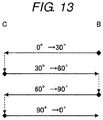
- Fig. 13 is an explanatory diagram illustrating a rotation operation example of the antenna 22 in a case where a rotation operation is performed during a movement operation.
- the rotation controller 116 may control rotation of the antenna 22 while the antenna 22 is moving from the point B to the point C or while the antenna 22 is moving from the point C to the point B.
- the example in Fig. 13 illustrates an example in which the antenna 22 is rotated in a clockwise direction in increments 30°. In this case, the antenna 22 is rotated from 0° to 90° in 1.5 reciprocations between point B and point C. Accordingly, it is possible to rotate the antenna 22 up to 90° in a shorter time than the example illustrated in Fig. 11 and it is possible to more efficiently read information from the RFID tag.
- the reading device 2 in the above embodiments has been applied to a case where information saved in the RFID tag T attached to the merchandise M is being read.
- the reading device 2 can also be used as an RFID tag writing device for writing information to the RFID tags T. That is, the antenna 22 may also record merchandise registrations by writing predetermined information to the RFID tag T. This writing to the tags may be conducted in conjunction with the reading of the tags.
- the information written to the RFID tag T can be used not only as information indicating that the merchandise has been registered but also as information for security purposes.
- the antenna 22 is rotated while being reciprocated.
- a moving method is not limited to the above example.
- the antenna 22 may be rotated from 0° to 90° while moving one-way from the point B to the point C.
- an operation example in which the antenna 22 is moved only in a uni-axial direction e.g., along x-axis
- the configuration in which the antenna 22 linearly moves in the x-axis direction is described.
- the antenna 22 may be configured to move along a curved path.
- a program executed by each of the devices according to the embodiment describe above can be provided in advance in a storage medium (ROM or storage unit).
- the program is not limited thereto.
- the program may be configured to be recorded and provided in a computer-readable recording medium such as a CD-ROM, a flexible disk (FD), a CD-R, a Digital Versatile Disk (DVD), or the like as a file in installable format or executable format.
- the storage medium may be an embedded system within the computer.
- the storage medium may also be a storage medium from which a program is transmitted via a LAN, the Internet, or the like to be downloaded and stored or temporarily stored in another device for execution.
- the program executed by each of the devices according to the embodiments describe above may be saved on a computer connected to a network such as the Internet and provided by downloading the program via a network, and the program may be provided and distributed via a network such as the Internet.
- the antenna 22 is rotated around a traveling direction of a linearly polarized wave and also moved in parallel with the antenna surface. Accordingly, it is possible to widen a reading area that has high electric field intensity and thus improve information communication efficiency and reading accuracy while taking an advantage of the linearly polarized wave output. It is thus possible to read information from tags oriented in any direction of an in-plane direction of the antenna surface by linearly polarized waves in substantially the same manner as circularly polarized waves. That is, according to the present disclosure, it is possible to prevent failed readings of the arbitrarily oriented RFID tags and to improve efficiency of the reading process.
Landscapes
- Engineering & Computer Science (AREA)
- Toxicology (AREA)
- Physics & Mathematics (AREA)
- Health & Medical Sciences (AREA)
- Artificial Intelligence (AREA)
- General Health & Medical Sciences (AREA)
- Electromagnetism (AREA)
- Computer Vision & Pattern Recognition (AREA)
- General Physics & Mathematics (AREA)
- Theoretical Computer Science (AREA)
- Computer Networks & Wireless Communication (AREA)
- Cash Registers Or Receiving Machines (AREA)
- Support Of Aerials (AREA)
Applications Claiming Priority (1)
| Application Number | Priority Date | Filing Date | Title |
|---|---|---|---|
| JP2016161219A JP2018028849A (ja) | 2016-08-19 | 2016-08-19 | 読取装置およびプログラム |
Publications (1)
| Publication Number | Publication Date |
|---|---|
| EP3285200A1 true EP3285200A1 (de) | 2018-02-21 |
Family
ID=59683436
Family Applications (1)
| Application Number | Title | Priority Date | Filing Date |
|---|---|---|---|
| EP17186859.9A Withdrawn EP3285200A1 (de) | 2016-08-19 | 2017-08-18 | Lesevorrichtung und steuerungsprogramm für lesevorrichtung |
Country Status (3)
| Country | Link |
|---|---|
| US (2) | US9977934B2 (de) |
| EP (1) | EP3285200A1 (de) |
| JP (1) | JP2018028849A (de) |
Cited By (1)
| Publication number | Priority date | Publication date | Assignee | Title |
|---|---|---|---|---|
| CN109244653A (zh) * | 2018-11-08 | 2019-01-18 | 广州安的电子科技有限公司 | 天线组件、天线层板及无人售卖装置 |
Families Citing this family (9)
| Publication number | Priority date | Publication date | Assignee | Title |
|---|---|---|---|---|
| KR101589880B1 (ko) * | 2015-10-01 | 2016-02-01 | 남상용 | Rfid태그 정보입력장치 |
| JP7007170B2 (ja) * | 2017-12-13 | 2022-01-24 | 東芝テック株式会社 | 無線タグ読取装置及びプログラム |
| CN109271820B (zh) * | 2018-10-18 | 2024-01-23 | 成都芯创智联科技股份有限公司 | 一种rfid单头全向动态扫描系统及快速扫描方法 |
| JP7014442B2 (ja) | 2019-07-03 | 2022-02-01 | Necプラットフォームズ株式会社 | 読取装置 |
| JP7321855B2 (ja) * | 2019-09-13 | 2023-08-07 | 東芝テック株式会社 | 無線タグ読取装置及び無線タグ読取方法 |
| JPWO2022191153A1 (de) * | 2021-03-08 | 2022-09-15 | ||
| JP7692751B2 (ja) * | 2021-07-16 | 2025-06-16 | 東芝テック株式会社 | 無線タグ読取装置 |
| JP2023028823A (ja) * | 2021-08-20 | 2023-03-03 | 東芝テック株式会社 | 通信装置 |
| JP2025091833A (ja) * | 2023-12-07 | 2025-06-19 | 電気興業株式会社 | 無線中継器および無線中継システム |
Citations (4)
| Publication number | Priority date | Publication date | Assignee | Title |
|---|---|---|---|---|
| EP2474939A1 (de) * | 2010-09-15 | 2012-07-11 | Omron Corporation | Rfid-tag und rfid-system |
| EP2808831A1 (de) * | 2012-01-26 | 2014-12-03 | Hanmi IT Co., Ltd. | Scanner, scanvorrichtung und scanverfahren für ein regal |
| CN204215427U (zh) * | 2014-12-01 | 2015-03-18 | 南京大学 | 一种基于rfid技术的龙门式自动扫描识别装置 |
| US20150302708A1 (en) * | 2014-04-18 | 2015-10-22 | Toshiba Tec Kabushiki Kaisha | Self-checkout apparatus and self-checkout method |
Family Cites Families (10)
| Publication number | Priority date | Publication date | Assignee | Title |
|---|---|---|---|---|
| JP4095467B2 (ja) * | 2003-02-26 | 2008-06-04 | 東芝テック株式会社 | 無線タグ読取装置 |
| JP4347673B2 (ja) | 2003-11-27 | 2009-10-21 | 東芝テック株式会社 | 無線タグ読取装置 |
| JP4305420B2 (ja) * | 2005-06-24 | 2009-07-29 | ブラザー工業株式会社 | 質問器 |
| JP4607802B2 (ja) * | 2006-03-16 | 2011-01-05 | 富士通株式会社 | Rfidリーダライタ |
| JP2008123231A (ja) * | 2006-11-10 | 2008-05-29 | Hitachi Ltd | Rfidタグ読取システムおよびrfidタグ読取方法 |
| US8400269B2 (en) * | 2007-08-30 | 2013-03-19 | Round Rock Research, Llc | Methods and systems using polarization modulated electromagnetic waves |
| US8743006B2 (en) * | 2007-10-31 | 2014-06-03 | Nitta Corporation | Wireless communication-improving sheet member, wireless IC tag, antenna, and wireless communication system using the same |
| JP4841659B2 (ja) * | 2009-09-11 | 2011-12-21 | 東芝テック株式会社 | アンテナ装置 |
| JP6099872B2 (ja) * | 2012-03-15 | 2017-03-22 | オムロン株式会社 | Rfidリーダライタおよびrfidタグシステム |
| FI124728B (en) * | 2012-10-08 | 2014-12-31 | Nordic Id Oy | RFID device antenna |
-
2016
- 2016-08-19 JP JP2016161219A patent/JP2018028849A/ja active Pending
-
2017
- 2017-07-05 US US15/642,106 patent/US9977934B2/en active Active
- 2017-08-18 EP EP17186859.9A patent/EP3285200A1/de not_active Withdrawn
-
2018
- 2018-04-20 US US15/958,910 patent/US10181062B2/en active Active
Patent Citations (4)
| Publication number | Priority date | Publication date | Assignee | Title |
|---|---|---|---|---|
| EP2474939A1 (de) * | 2010-09-15 | 2012-07-11 | Omron Corporation | Rfid-tag und rfid-system |
| EP2808831A1 (de) * | 2012-01-26 | 2014-12-03 | Hanmi IT Co., Ltd. | Scanner, scanvorrichtung und scanverfahren für ein regal |
| US20150302708A1 (en) * | 2014-04-18 | 2015-10-22 | Toshiba Tec Kabushiki Kaisha | Self-checkout apparatus and self-checkout method |
| CN204215427U (zh) * | 2014-12-01 | 2015-03-18 | 南京大学 | 一种基于rfid技术的龙门式自动扫描识别装置 |
Cited By (2)
| Publication number | Priority date | Publication date | Assignee | Title |
|---|---|---|---|---|
| CN109244653A (zh) * | 2018-11-08 | 2019-01-18 | 广州安的电子科技有限公司 | 天线组件、天线层板及无人售卖装置 |
| CN109244653B (zh) * | 2018-11-08 | 2024-05-14 | 广州安的电子科技有限公司 | 天线组件、天线层板及无人售卖装置 |
Also Published As
| Publication number | Publication date |
|---|---|
| US9977934B2 (en) | 2018-05-22 |
| US10181062B2 (en) | 2019-01-15 |
| JP2018028849A (ja) | 2018-02-22 |
| US20180239935A1 (en) | 2018-08-23 |
| US20180053022A1 (en) | 2018-02-22 |
Similar Documents
| Publication | Publication Date | Title |
|---|---|---|
| US10181062B2 (en) | Reading device and control program for reading device | |
| US11087303B2 (en) | Method for reading information from electronic tag | |
| US9858769B2 (en) | Self-checkout apparatus and self-checkout method | |
| EP3285201B1 (de) | Lesevorrichtung und steuerungsprogramm für lesevorrichtung | |
| JP6936087B2 (ja) | 読取装置およびプログラム | |
| US10860818B2 (en) | Communication apparatus, communication method, and computer program | |
| US10599891B2 (en) | Antenna control apparatus | |
| JP7483530B2 (ja) | 情報読取装置、無線タグリーダ、およびコードリーダ | |
| JP2018018195A (ja) | 物品読取装置 | |
| US20180039801A1 (en) | Tag reading device and control program for tag reading device | |
| EP3454276A1 (de) | Lesevorrichtung und verfahren zum lesen von informationen von rfid-etiketten damit | |
| US11217071B2 (en) | Reading apparatus | |
| JP6679653B2 (ja) | セルフチェックアウト装置及びプログラム | |
| JP2019191919A (ja) | レジシステム及びレジ精算方法 | |
| JP7345367B2 (ja) | 情報処理装置、情報処理システム、およびプログラム | |
| US20200143126A1 (en) | Reading apparatus and method for reading information from rfid tag by the same | |
| JP7844364B2 (ja) | 商品情報読取装置およびプログラム |
Legal Events
| Date | Code | Title | Description |
|---|---|---|---|
| PUAI | Public reference made under article 153(3) epc to a published international application that has entered the european phase |
Free format text: ORIGINAL CODE: 0009012 |
|
| STAA | Information on the status of an ep patent application or granted ep patent |
Free format text: STATUS: THE APPLICATION HAS BEEN PUBLISHED |
|
| AK | Designated contracting states |
Kind code of ref document: A1 Designated state(s): AL AT BE BG CH CY CZ DE DK EE ES FI FR GB GR HR HU IE IS IT LI LT LU LV MC MK MT NL NO PL PT RO RS SE SI SK SM TR |
|
| AX | Request for extension of the european patent |
Extension state: BA ME |
|
| STAA | Information on the status of an ep patent application or granted ep patent |
Free format text: STATUS: REQUEST FOR EXAMINATION WAS MADE |
|
| 17P | Request for examination filed |
Effective date: 20180821 |
|
| RBV | Designated contracting states (corrected) |
Designated state(s): AL AT BE BG CH CY CZ DE DK EE ES FI FR GB GR HR HU IE IS IT LI LT LU LV MC MK MT NL NO PL PT RO RS SE SI SK SM TR |
|
| STAA | Information on the status of an ep patent application or granted ep patent |
Free format text: STATUS: EXAMINATION IS IN PROGRESS |
|
| 17Q | First examination report despatched |
Effective date: 20191011 |
|
| STAA | Information on the status of an ep patent application or granted ep patent |
Free format text: STATUS: THE APPLICATION IS DEEMED TO BE WITHDRAWN |
|
| 18D | Application deemed to be withdrawn |
Effective date: 20210212 |