EP3286460B1 - Mécanisme de changement de vitesse pour une boîte à vitesses de véhicule - Google Patents
Mécanisme de changement de vitesse pour une boîte à vitesses de véhicule Download PDFInfo
- Publication number
- EP3286460B1 EP3286460B1 EP15717902.9A EP15717902A EP3286460B1 EP 3286460 B1 EP3286460 B1 EP 3286460B1 EP 15717902 A EP15717902 A EP 15717902A EP 3286460 B1 EP3286460 B1 EP 3286460B1
- Authority
- EP
- European Patent Office
- Prior art keywords
- detent
- shift shaft
- shift
- longitudinal axis
- track
- Prior art date
- Legal status (The legal status is an assumption and is not a legal conclusion. Google has not performed a legal analysis and makes no representation as to the accuracy of the status listed.)
- Not-in-force
Links
- 230000007246 mechanism Effects 0.000 title claims description 57
- 230000005540 biological transmission Effects 0.000 title claims description 15
- 230000006835 compression Effects 0.000 claims description 16
- 238000007906 compression Methods 0.000 claims description 16
- 230000000694 effects Effects 0.000 claims description 7
- 238000006073 displacement reaction Methods 0.000 description 7
- 230000007935 neutral effect Effects 0.000 description 6
- 230000000630 rising effect Effects 0.000 description 3
- 230000001419 dependent effect Effects 0.000 description 1
- 238000009434 installation Methods 0.000 description 1
Images


Classifications
-
- F—MECHANICAL ENGINEERING; LIGHTING; HEATING; WEAPONS; BLASTING
- F16—ENGINEERING ELEMENTS AND UNITS; GENERAL MEASURES FOR PRODUCING AND MAINTAINING EFFECTIVE FUNCTIONING OF MACHINES OR INSTALLATIONS; THERMAL INSULATION IN GENERAL
- F16H—GEARING
- F16H63/00—Control outputs from the control unit to change-speed- or reversing-gearings for conveying rotary motion or to other devices than the final output mechanism
- F16H63/02—Final output mechanisms therefor; Actuating means for the final output mechanisms
- F16H63/30—Constructional features of the final output mechanisms
- F16H63/38—Detents
Definitions
- the present invention relates to a gear shift mechanism for a vehicle transmission, the gear shift mechanism comprising a shift shaft, an actuator for acting on the shift shaft to move it between at least two positions, and a detent mechanism including a detent, a detent track having at least one valley, and a spring urging the detent onto the detent track, the detent mechanism being arranged such that the detent moves relative to the detent track responsive to shift shaft movements and reaches a valley when the shift shaft reaches one of the at least two positions to engage the shift shaft there.
- Such gear shift mechanisms are utilized in various configurations to change the state of a transmission in response to movement of an input element by the driver.
- a semi-automatic transmission also known as clutch-less manual transmission, automated manual transmission, flap-py-paddle gearbox, or paddle-shift gearbox. This eliminates the need for a clutch pedal which the driver otherwise needs to depress before making a gear change, since the clutch itself is actuated by electronic equipment which can synchronize the timing and torque required to make quick, smooth gear shifts.
- Input commands can also be transmitted by a cable or other transmission means to a shift shaft of the transmission, wherein the cable or other transmission means acts as an actuator on the shift shaft to move the shift shaft along its longitudinal direction.
- the shift shaft is provided with a detent track extending along its longitudinal direction and comprising a central valley and a further valley in each direction along its longitudinal direction.
- a detent is biased by a spring which is oriented perpendicular to the longitudinal direction of the shift shaft and which biases the detent to be pressed onto the detent track.
- the central valley of the detent track corresponds to the neutral position, and the two adjacent valleys correspond to in gear positions.
- a shift mechanism of this kind is for example described in JP 2014-152822 A . This document describes a shift mechanism comprising the features of the preamble of claim 1.
- shift mechanisms transmitting a movement of an input element, such as a shift lever, via an actuator, for example a cable, to a shift shaft to move the shift shaft along its longitudinal direction or to turn it about its longitudinal axis.
- an actuator for example a cable
- An example for a mechanism of the latter kind is described in WO 2007/129902 A1 in which a servo actuator acts on an actuation lever connected to and extending perpendicular to the shift shaft to turn the shift shaft about its longitudinal axis.
- a further lever is connected to the shift shaft and carries a detent at its outer end which is urged by a spring within the lever onto a stationary detent track having three valleys corresponding to three turning states of the shift shaft.
- a further gear shift mechanism is known from EP 2 140 176 B1 .
- the gear shift system comprises a shift lever to which a shift cable is connected which transmits shift lever movements to an input actuating member which is part of a transmission mechanism for transferring shift commands from the shift lever to the shift shaft.
- the input actuating member is in this case a valve control lever which is rotatably connected to a shift actuation lever which is fixed to the shift shaft and extends perpendicular therefrom.
- a servo cylinder is controlled by a servo valve arrangement and coupled to the shift actuation lever so that it can assist in turning the shift shaft about its longitudinal axis.
- the valve control lever comprises an annular portion with an opening through which the shift shaft extends with limited play.
- the rotatable connection of the valve control lever to the shift actuation lever is disposed such that the axis of rotation of this connection is parallel to the longitudinal axis of the shift shaft but at a distance to the longitudinal axis of the shift shaft.
- the servo valve arrangement comprises two opposing servo valves with spring biased plungers which abut against opposite outer surface portions of the annular portion of the valve control lever.
- the connection between the valve control arm and the shift actuation lever is a connection with limited play, since the valve control arm may rotate with respect to the shift actuation lever but this rotation is limited by the shift shaft which extends through the annular end portion of the valve control arm and thus limits the rotational moving range.
- Such limited play connection also in principle allows for a purely mechanical actuation of the shift shaft in case of a servo failure, since after the limited shift is used up manual force is transferred through the transmission mechanism to the shift actuation lever which then turns the shift shaft.
- valve control lever If the valve control lever is pivoted by a longitudinal displacement of the shift cable caused by a shift lever movement, the valve control lever on the one hand transfers torque to the shift actuation lever, on the other hand the valve control arm is rotated around its rotatable connection to the shift actuation lever which causes a displacement of its annular portion.
- This shift in the relative positioning is controlling the servo mechanism since the rotation of the valve control arm and the corresponding displacement of its annular end portion lead to a displacement of the plunger of the servo valve arrangement which in turn activate the servo cylinder which then exerts a torque on the shift shaft by exerting a force on the shift actuation lever to perform the desired shift movement of the shift shaft.
- a detent mechanism comprising a spring biased detent and a cooperating detent track is acting between the valve control lever and a part fixed with respect to the gearbox housing.
- the detent track is formed on one end portion of the valve control lever and comprises three valleys corresponding to the two shifted positions and the neutral position in the middle.
- a spring which is oriented perpendicular to the longitudinal axis of the shift shaft urges the detent onto the detent track.
- the detent mechanism such that it is acting between (i) the input actuating member or a component that is linked to the input actuating member such that it follows its movements, and (ii) the shift actuation lever or a component that is linked to the shift actuation lever such that it follows its turning movements, so that the detent reaching a central valley of the detent track indicates that the shift shaft has reached its neutral or in-gear position as dictated by the input actuating member.
- a detent track having a single central valley is sufficient since the detent mechanism is giving an indication whether the shift shaft reached the position dictated by the input actuating member which is a single bit information.
- the detent mechanism indicates, when the detent reaches the central valley of the detent track, that the shift shaft reached its rotational shift position that is dictated by the shift actuating member, regardless whether this dictated position is the neutral position, the forward shifted position or the backward shifted position.
- the present invention is also applicable to shift mechanisms having a detent and a detent track with only a single valley.
- gear shift mechanisms utilizing a detent mechanism have in common that the spring that is urging the detent onto the detent track is oriented perpendicular to the detent track such that it can exert a force that is perpendicular to the detent track.
- the spring of the detent mechanism is oriented with its longitudinal axis perpendicular to the longitudinal axis of the shift shaft.
- the spring is a compression or helical spring and has a certain extension in axial direction of the helical spring.
- the spring of the detent mechanism is disposed such that its compression force is directed parallel to the longitudinal axis of the shift shaft.
- the spring is acting on a push body which is moveably amounted in the direction of the longitudinal axis of the spring.
- the push body is in contact with the detent, and at least one of the contact surfaces of the push body and the detent is at least partially inclined such that a force on the push body in a direction parallel to the longitudinal axis of the shift shaft is transmitted to a force perpendicular to the longitudinal axis of the shift shaft and onto the detent track when the detent is displaced from the centre of the valley.
- the spring is arranged with its longitudinal axis parallel to the longitudinal axis of the shift shaft which allows for a much more space efficient arrangement compared to the prior art where the spring with its longitudinal axis has been oriented perpendicular to the longitudinal axis of the shift shaft.
- the detent mechanism includes a housing having a first cylindrical cavity. In this first cylindrical cavity the spring and part of the push body are received, wherein the longitudinal axis of the first cylindrical cavity is parallel to the longitudinal axis of the shift shaft.
- a second cylindrical cavity in the housing is merging with the first the cylindrical cavity so that the push body is disposed in the merging area of the first and second cylindrical cavities.
- the longitudinal axis of the second cylindrical cavity is perpendicular to the longitudinal axis of the shift shaft.
- the detent is slidably received in the second cylindrical cavity such that the push body is able to urge the detent to move towards the detent track.
- the push body has a spherical surface tip facing the detent and the detent has a valley in its outer surface.
- the valley is arranged to be able to receive a portion of the spherical surface of the push body. In this manner the push body exerts a force on the detent along its longitudinal axis further compressing the spring when the push body is displaced from the center of the valley in the outer surface of the detent.
- this valley in the outer surface of the detent is formed by a circumferential groove extending around the circumference of a piston-like body of the detent.
- the push body and the detent each have a wedge surface portion which wedge surface portions are in contact with each other and which are inclined with respect to the longitudinal direction of the shift shaft and inclined with respect to the direction of the compression force of the spring.
- the wedge surface portions in contact with each other create a wedge effect which deflects the compression force of the spring which is directed parallel to the longitudinal axis of the shift shaft into a force perpendicular thereto urging the detent onto the detent track.
- the angle of inclination of the wedge surface portions with respect to the longitudinal direction of the shift shaft is about 45°.
- the gear shift mechanism is arranged to effect shift shaft movements along its longitudinal axis, in that the detent track is formed on the outer surface of the shift shaft or of component fixed to the shift shaft and extends along its longitudinal direction, and in that the spring is arranged parallel to the detent track and parallel to the longitudinal axis of the shift shaft above the detent track.
- the gear shift mechanism is arranged to effect a shift shaft movement by turning the shift shaft about its longitudinal axis by exerting force on a shift actuation lever extending perpendicular to the shift shaft. This results in a torque on the shift shaft.
- the detent and the detent track are arranged such that the detent moves along the detent track in response to pivotal movements of the shift actuation lever.
- the spring is disposed such that its compression force is directed perpendicular to the shift actuation lever.
- the detent carries at its end facing the detent track a ball which is in contact with the detent track.
- the ball is mounted in a tip portion of the detent to be rotatable therein.
- the detent can have the form of a piston which is moveable in a direction perpendicular to the detent track so that it is moved up and down when the detent slides along an elevation on the detent track.
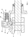
- the detent track 10 is formed on the outer surface of a sleeve 4 which is fixed to the shift shaft 2 such that it follows its movement.
- the detent track 10 has a central valley 11 and an adjacent valley 14 in one direction and an adjacent valley 16 in the opposite direction. Between adjacent valleys a crest 12 is formed.
- Such a shifter mechanism can for example be employed in a semi-automatic transmission in which gear changes are effected by tipping on a rocker on the steering wheel.
- the detent mechanism comprises a housing 34 stationary with respect to the transmission.
- This housing has two bores or cylindrical cavities, namely a first cylindrical cavity 36 with an axial direction parallel to the longitudinal axis of the shift shaft 2, and a second cylindrical cavity 38 with an axial direction perpendicular to the longitudinal axis of the shift shaft 2.
- the first cylindrical cavity 36 opens into the second cylindrical cavity 38.
- a compression spring 30 is disposed which acts between a bottom wall of the first cylindrical cavity 36 and a push body 40.
- the push body 40 is formed by a ball. The ball is received in the first cylindrical cavity 36 such that it can perform sliding movements along the axial direction within the firs cylindrical cavity 36.
- a detent 20 is disposed that can slide along the longitudinal axis of the second cylindrical cavity 38.
- the plunger or detent 20 carries a ball 26 at its outer end facing the detent track 10.
- the detent 20 is provided with a valley 22 in its outer surface. This valley 22 can be formed by a circumferential groove extending around the detent 20.
- the valley 22 is dimensioned such that it can receive a spherical front portion of the push body 40 in the form of a ball.
- the valley 22 in the detent 20 has a valley centre 24, and on opposite sides of the valley centre 24 inclined side wall portions rising up to the outer surface of the detent outside of the valley.
- the inclined wall portions of the valley 22 are inclined both with respect to the longitudinal axis of the first cylindrical cavity 36 and with respect to the longitudinal axis of the second cylindrical cavity 38.
- inclined an orientation is meant which is noticeably different from 0° and 90° with respect to the mentioned directions.
- the inclined side portions of the valley 22 cooperate with the inclined or curved surface portions of the ball of the push body 40 to effect a wedge function which is suitable to deflect the force of the compression spring 30 along the longitudinal direction of the first cylindrical cavity 36 to a force perpendicular thereto acting on detent 20 along the longitudinal direction of the second cylindrical cavity 38.
- Fig. 1 shows the detent mechanism of the gear shifter mechanism in its centre, neutral position which means that the ball 26 of the detent 20 is disposed with its outer tip portion in the centre 9 of the central valley 11.
- the push body 40 in the form of a ball is located in the centre 24 of the valley 22 in the outer surface of the detent 20. It should be noted that in this centered position no force is exerted on the detent 20 towards the detent track 10 because the inclined side wall portions of the valley 22 and the tip portion on the ball of the push body 40 are symmetrical so that no net force on the detent is generated in the direction of longitudinal axis of the second cylindrical cavity 38.
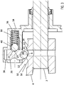
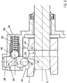
- a shift actuation movement has started which causes a movement of the shift shaft 2 along its longitudinal axis (to the right hand side in Fig. 2 and the following Figs. 3 to 6 ).
- the ball 26 of the detent 20 has started to move out of its centered location in the central valley 11 of the detent track 10.
- the central valley is rising rather smoothly at the beginning the displacement of the ball 26 of the detent 20 has not yet resulted in a noticeable displacement of the detent 20 along the longitudinal direction of the second cylindrical cavity 38, i.e. the detent has not yet start to move upwards to a noticeable extent.
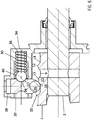
- Fig. 7 shows the shift shaft 2 in its opposite in-gear position with the detent 20 with its ball 26 engaged in the other adjacent valley 14.
- the movement states for a movement of the shift shaft from the neutral position as shown in Fig. 1 to the opposite in-gear position as shown in Fig. 7 correspond to the movement states as shown and explained in connection with Figs. 2 to 6 in a symmetric manner in the opposite direction.
- the arrangement according to the present invention with the spring 30 extending with its longitudinal axis parallel to the longitudinal axis of the shift shaft 2 allows for a more compact design of the gear shift mechanism.
- the spring 30 would be disposed with its longitudinal axis extending along the longitudinal axis of the second cylindrical cavity 38, and the spring 30 would, in the views of the Figures, be located vertically on top of the detent 20.
Landscapes
- Engineering & Computer Science (AREA)
- General Engineering & Computer Science (AREA)
- Mechanical Engineering (AREA)
- Gear-Shifting Mechanisms (AREA)
Claims (10)
- Mécanisme de changement de vitesse pour une boîte à vitesses de véhicule, le mécanisme de changement de vitesse comprenant un arbre de changement de vitesse (2), un actionneur pour agir sur l'arbre de changement de vitesse afin de le déplacer entre au moins deux positions, et un mécanisme d'enclenchement comportant un élément d'enclenchement (20), un chemin d'enclenchement (10) ayant au moins un creux (11, 14, 16), et un ressort (30) amenant l'élément d'enclenchement sur le chemin d'enclenchement, le mécanisme d'enclenchement étant agencé de telle sorte que l'élément d'enclenchement se déplace par rapport au chemin d'enclenchement en réponse aux mouvements de l'arbre de changement de vitesse et atteint un creux lorsque l'arbre de changement de vitesse atteint l'une des au moins deux positions pour que l'arbre de changement de vitesse se mette en prise dans celle-ci, caractérisé en ce que le ressort (30) est disposé de telle sorte que sa force de compression soit dirigée parallèlement à l'axe longitudinal de l'arbre de changement de vitesse (2), le ressort (30) agit sur un corps de poussée (40) qui est en contact avec l'élément d'enclenchement (20), et au moins l'une des surfaces de contact du corps de poussée (40) et de l'élément d'enclenchement (20) est au moins partiellement inclinée de telle sorte que la force du ressort sur le corps de poussée (40) dans une direction parallèle à l'axe longitudinal de l'arbre de changement de vitesse (2) est transmise à une force sur l'élément d'enclenchement (20) perpendiculaire à l'axe longitudinal de l'arbre de changement de vitesse (2) et sur le chemin d'enclenchement (10) lorsque l'élément d'enclenchement (20) est déplacé par rapport au centre du creux.
- Mécanisme de changement de vitesse selon la revendication 1, caractérisé en ce que le mécanisme d'enclenchement comprend un logement (34) comportant une première cavité cylindrique (36) dans laquelle sont reçus le ressort (30) et une partie du corps de poussée (40), l'axe longitudinal de la première cavité cylindrique (36) étant orienté parallèlement à l'axe longitudinal de l'arbre de changement de vitesse (2), et une seconde cavité cylindrique (38) se fondant dans la première cavité cylindrique (36), l'axe longitudinal de la seconde cavité cylindrique (38) étant perpendiculaire à l'axe longitudinal de l'arbre de changement de vitesse (2), l'élément d'enclenchement (20) étant reçu de manière coulissante dans la seconde cavité cylindrique (38) pour amener l'élément d'enclenchement (20) à se déplacer vers le chemin d'enclenchement (10).
- Mécanisme de changement de vitesse selon la revendication 1 ou 2, caractérisé en ce que le corps de poussée (40) a une surface sphérique faisant face à l'élément d'enclenchement (20) et en ce que l'élément d'enclenchement (20) a un creux (22) dans sa surface externe, lequel creux (22) est apte à recevoir une partie de la surface sphérique du corps de poussée (40) de telle sorte que le corps de poussée exerce une force sur l'élément d'enclenchement (20) le long de son axe longitudinal lorsque le corps de poussée (40) est déplacé par rapport au centre (24) du creux (22) dans la surface externe de l'élément d'enclenchement (20).
- Mécanisme de changement de vitesse selon la revendication 3, caractérisé en ce que le creux (22) dans la surface externe de l'élément d'enclenchement (20) est formé par une gorge circonférentielle s'étendant autour d'un corps de l'élément d'enclenchement (20).
- Mécanisme de changement de vitesse selon la revendication 1 ou 2, caractérisé en ce que le corps de poussée et l'élément d'enclenchement ont chacun une partie en pente, lesquelles parties en pente sont en contact l'une avec l'autre et lesquelles sont inclinées par rapport à la direction longitudinale de l'arbre de changement de vitesse et inclinées par rapport à la direction de la force de compression du ressort.
- Mécanisme de changement de vitesse selon la revendication 5, caractérisé en ce que l'angle d'inclinaison des parties en pente par rapport à la direction longitudinale de l'arbre de changement de vitesse est d'environ 45°.
- Mécanisme de changement de vitesse selon l'une quelconque des revendications précédentes, caractérisé en ce que le mécanisme de changement de vitesse est agencé pour effectuer les mouvements de l'arbre de changement de vitesse le long de son axe longitudinal, le chemin d'enclenchement (10) est formé sur la surface externe de l'arbre de changement de vitesse (2) ou sur la surface externe d'un composant fixé à l'arbre de changement de vitesse et s'étend le long de la direction longitudinale de l'arbre de changement de vitesse, et en ce que le ressort (30) est agencé parallèlement au chemin d'enclenchement (10) et parallèlement à l'axe longitudinal de l'arbre de changement de vitesse (2) au-dessus du chemin d'enclenchement (10).
- Mécanisme de changement de vitesse selon l'une quelconque des revendications 1 à 6 précédentes, caractérisé en ce que le mécanisme de changement de vitesse est agencé pour effectuer des mouvements de l'arbre de changement de vitesse en faisant tourner l'arbre de changement de vitesse autour de son axe longitudinal en exerçant une force sur le levier de commande de changement de vitesse s'étendant perpendiculairement à l'arbre de changement de vitesse ce qui aboutit à un couple sur l'arbre de changement de vitesse, l'élément d'enclenchement et le chemin d'enclenchement (10) sont agencés de telle sorte que l'élément d'enclenchement se déplace le long du chemin d'enclenchement en réponse aux mouvements de pivotement du levier de commande de changement de vitesse, et en ce que le ressort est disposé de telle sorte que sa force de compression est dirigée perpendiculairement au levier de commande de changement de vitesse.
- Mécanisme de changement de vitesse selon l'une quelconque des revendications précédentes, caractérisé en ce que l'élément d'enclenchement (20) porte au niveau de son extrémité faisant face au chemin d'enclenchement (10) une bille (26) qui est en contact avec le chemin d'enclenchement.
- Mécanisme de changement de vitesse selon la revendication 9, caractérisé en ce que la bille (26) est montée dans une partie formant pointe de l'élément d'enclenchement (20) pour pouvoir tourner à l'intérieur.
Applications Claiming Priority (1)
| Application Number | Priority Date | Filing Date | Title |
|---|---|---|---|
| PCT/EP2015/058840 WO2016169605A1 (fr) | 2015-04-23 | 2015-04-23 | Mécanisme de changement de vitesse pour une boîte à vitesses de véhicule |
Publications (2)
| Publication Number | Publication Date |
|---|---|
| EP3286460A1 EP3286460A1 (fr) | 2018-02-28 |
| EP3286460B1 true EP3286460B1 (fr) | 2019-03-27 |
Family
ID=52997450
Family Applications (1)
| Application Number | Title | Priority Date | Filing Date |
|---|---|---|---|
| EP15717902.9A Not-in-force EP3286460B1 (fr) | 2015-04-23 | 2015-04-23 | Mécanisme de changement de vitesse pour une boîte à vitesses de véhicule |
Country Status (3)
| Country | Link |
|---|---|
| EP (1) | EP3286460B1 (fr) |
| CN (1) | CN107532714A (fr) |
| WO (1) | WO2016169605A1 (fr) |
Families Citing this family (2)
| Publication number | Priority date | Publication date | Assignee | Title |
|---|---|---|---|---|
| US10337553B2 (en) | 2017-04-11 | 2019-07-02 | Ford Global Technologies, Llc | Spring-loaded cable attachement |
| EP4170205B1 (fr) * | 2021-10-25 | 2024-10-09 | ZF CV Systems Europe BV | Boîte de vitesses utilisant une goupille d'arrêt à double usage |
Family Cites Families (8)
| Publication number | Priority date | Publication date | Assignee | Title |
|---|---|---|---|---|
| BE495172A (fr) * | ||||
| DE3437434A1 (de) * | 1984-10-12 | 1986-04-17 | Dr.Ing.H.C. F. Porsche Ag, 7000 Stuttgart | Schaltvorrichtung fuer ein kraftfahrzeug-wechselgetriebe |
| JP3377154B2 (ja) * | 1996-02-15 | 2003-02-17 | 日野自動車株式会社 | 変速機のギヤシフト装置 |
| JP4758505B2 (ja) * | 2006-04-26 | 2011-08-31 | スカニア シーブイ アクチボラグ(パブル) | 制御配置及びギアボックス |
| SE530136C2 (sv) * | 2006-05-10 | 2008-03-11 | Kongsberg Automotive As | Anordning och metod för att ändra växel i mekaniska växellådor |
| EP1975472B1 (fr) * | 2007-03-26 | 2012-05-16 | Kongsberg Automotive AS | Servo-réduction de changement de vitesses mécanique |
| DE102011009831A1 (de) * | 2011-01-31 | 2012-08-02 | Schaeffler Technologies Gmbh & Co. Kg | Schaltelementverriegelung |
| JP2014152822A (ja) * | 2013-02-06 | 2014-08-25 | Honda Motor Co Ltd | 変速機のギヤ締結装置 |
-
2015
- 2015-04-23 CN CN201580079089.8A patent/CN107532714A/zh active Pending
- 2015-04-23 EP EP15717902.9A patent/EP3286460B1/fr not_active Not-in-force
- 2015-04-23 WO PCT/EP2015/058840 patent/WO2016169605A1/fr not_active Ceased
Non-Patent Citations (1)
| Title |
|---|
| None * |
Also Published As
| Publication number | Publication date |
|---|---|
| WO2016169605A1 (fr) | 2016-10-27 |
| EP3286460A1 (fr) | 2018-02-28 |
| CN107532714A (zh) | 2018-01-02 |
Similar Documents
| Publication | Publication Date | Title |
|---|---|---|
| EP2683960B1 (fr) | Actionneur d'embrayage à auto-ajustement pour le fonctionnement d'un embrayage de véhicule | |
| US8292055B2 (en) | Self-adjusting mechanisms for clutches | |
| US10935132B2 (en) | Gear shifting apparatus for multi-speed transmission for electric vehicles | |
| US7026770B2 (en) | Actuation device | |
| US8347752B2 (en) | Actuating device with shift carriage lock | |
| US5121649A (en) | Motorized gear shift control apparatus for a transmission gearbox, in particular for automotive vehicles | |
| US10975956B2 (en) | Force transmission device for a transmission | |
| WO2007129902A1 (fr) | Appareil et procede de changement de vitesse dans des boites de vitesses mecaniques | |
| EP3286460B1 (fr) | Mécanisme de changement de vitesse pour une boîte à vitesses de véhicule | |
| EP0898099B1 (fr) | Dispositif automatisé de changement de vitesse pour une boíte de transmission | |
| CN106051152A (zh) | 一种用于自动变速器的驻车及换档执行机构 | |
| KR101628104B1 (ko) | 차량용 변속조작기구 | |
| US9555777B2 (en) | Parking device for vehicle | |
| EP3143311B1 (fr) | Système de changement de rapport | |
| CN212106895U (zh) | 一种自动变速器液压换挡驻车系统 | |
| US6561331B1 (en) | Transmission unit for a vehicle | |
| KR100851373B1 (ko) | 수동 변속기용 자동 변속 조작 장치 | |
| US9989145B2 (en) | Drive selector | |
| US20140165768A1 (en) | Push down shifter with cross joint | |
| EP3242820B1 (fr) | Systéme de présélection d'un verrouillage de parc | |
| KR101612970B1 (ko) | 기어 시프팅 시스템 | |
| US20060266147A1 (en) | Shifter assembly for manual transmission | |
| US12529422B2 (en) | Gear-change selector module for a gearshift | |
| WO2014093860A1 (fr) | Sélecteur à poussée vers le bas avec raccord croisé | |
| CN107956869A (zh) | 用于停车锁的致动系统 |
Legal Events
| Date | Code | Title | Description |
|---|---|---|---|
| STAA | Information on the status of an ep patent application or granted ep patent |
Free format text: STATUS: THE INTERNATIONAL PUBLICATION HAS BEEN MADE |
|
| PUAI | Public reference made under article 153(3) epc to a published international application that has entered the european phase |
Free format text: ORIGINAL CODE: 0009012 |
|
| STAA | Information on the status of an ep patent application or granted ep patent |
Free format text: STATUS: REQUEST FOR EXAMINATION WAS MADE |
|
| 17P | Request for examination filed |
Effective date: 20171009 |
|
| AK | Designated contracting states |
Kind code of ref document: A1 Designated state(s): AL AT BE BG CH CY CZ DE DK EE ES FI FR GB GR HR HU IE IS IT LI LT LU LV MC MK MT NL NO PL PT RO RS SE SI SK SM TR |
|
| AX | Request for extension of the european patent |
Extension state: BA ME |
|
| DAV | Request for validation of the european patent (deleted) | ||
| DAX | Request for extension of the european patent (deleted) | ||
| GRAP | Despatch of communication of intention to grant a patent |
Free format text: ORIGINAL CODE: EPIDOSNIGR1 |
|
| STAA | Information on the status of an ep patent application or granted ep patent |
Free format text: STATUS: GRANT OF PATENT IS INTENDED |
|
| GRAS | Grant fee paid |
Free format text: ORIGINAL CODE: EPIDOSNIGR3 |
|
| INTG | Intention to grant announced |
Effective date: 20190122 |
|
| GRAA | (expected) grant |
Free format text: ORIGINAL CODE: 0009210 |
|
| STAA | Information on the status of an ep patent application or granted ep patent |
Free format text: STATUS: THE PATENT HAS BEEN GRANTED |
|
| AK | Designated contracting states |
Kind code of ref document: B1 Designated state(s): AL AT BE BG CH CY CZ DE DK EE ES FI FR GB GR HR HU IE IS IT LI LT LU LV MC MK MT NL NO PL PT RO RS SE SI SK SM TR |
|
| REG | Reference to a national code |
Ref country code: GB Ref legal event code: FG4D |
|
| REG | Reference to a national code |
Ref country code: CH Ref legal event code: EP |
|
| REG | Reference to a national code |
Ref country code: AT Ref legal event code: REF Ref document number: 1113489 Country of ref document: AT Kind code of ref document: T Effective date: 20190415 |
|
| REG | Reference to a national code |
Ref country code: IE Ref legal event code: FG4D |
|
| REG | Reference to a national code |
Ref country code: DE Ref legal event code: R096 Ref document number: 602015027116 Country of ref document: DE |
|
| PG25 | Lapsed in a contracting state [announced via postgrant information from national office to epo] |
Ref country code: LT Free format text: LAPSE BECAUSE OF FAILURE TO SUBMIT A TRANSLATION OF THE DESCRIPTION OR TO PAY THE FEE WITHIN THE PRESCRIBED TIME-LIMIT Effective date: 20190327 Ref country code: FI Free format text: LAPSE BECAUSE OF FAILURE TO SUBMIT A TRANSLATION OF THE DESCRIPTION OR TO PAY THE FEE WITHIN THE PRESCRIBED TIME-LIMIT Effective date: 20190327 Ref country code: NO Free format text: LAPSE BECAUSE OF FAILURE TO SUBMIT A TRANSLATION OF THE DESCRIPTION OR TO PAY THE FEE WITHIN THE PRESCRIBED TIME-LIMIT Effective date: 20190627 Ref country code: SE Free format text: LAPSE BECAUSE OF FAILURE TO SUBMIT A TRANSLATION OF THE DESCRIPTION OR TO PAY THE FEE WITHIN THE PRESCRIBED TIME-LIMIT Effective date: 20190327 |
|
| REG | Reference to a national code |
Ref country code: NL Ref legal event code: MP Effective date: 20190327 |
|
| PG25 | Lapsed in a contracting state [announced via postgrant information from national office to epo] |
Ref country code: BG Free format text: LAPSE BECAUSE OF FAILURE TO SUBMIT A TRANSLATION OF THE DESCRIPTION OR TO PAY THE FEE WITHIN THE PRESCRIBED TIME-LIMIT Effective date: 20190627 Ref country code: GR Free format text: LAPSE BECAUSE OF FAILURE TO SUBMIT A TRANSLATION OF THE DESCRIPTION OR TO PAY THE FEE WITHIN THE PRESCRIBED TIME-LIMIT Effective date: 20190628 Ref country code: LV Free format text: LAPSE BECAUSE OF FAILURE TO SUBMIT A TRANSLATION OF THE DESCRIPTION OR TO PAY THE FEE WITHIN THE PRESCRIBED TIME-LIMIT Effective date: 20190327 Ref country code: RS Free format text: LAPSE BECAUSE OF FAILURE TO SUBMIT A TRANSLATION OF THE DESCRIPTION OR TO PAY THE FEE WITHIN THE PRESCRIBED TIME-LIMIT Effective date: 20190327 Ref country code: HR Free format text: LAPSE BECAUSE OF FAILURE TO SUBMIT A TRANSLATION OF THE DESCRIPTION OR TO PAY THE FEE WITHIN THE PRESCRIBED TIME-LIMIT Effective date: 20190327 Ref country code: NL Free format text: LAPSE BECAUSE OF FAILURE TO SUBMIT A TRANSLATION OF THE DESCRIPTION OR TO PAY THE FEE WITHIN THE PRESCRIBED TIME-LIMIT Effective date: 20190327 |
|
| REG | Reference to a national code |
Ref country code: AT Ref legal event code: MK05 Ref document number: 1113489 Country of ref document: AT Kind code of ref document: T Effective date: 20190327 |
|
| PG25 | Lapsed in a contracting state [announced via postgrant information from national office to epo] |
Ref country code: CZ Free format text: LAPSE BECAUSE OF FAILURE TO SUBMIT A TRANSLATION OF THE DESCRIPTION OR TO PAY THE FEE WITHIN THE PRESCRIBED TIME-LIMIT Effective date: 20190327 Ref country code: SK Free format text: LAPSE BECAUSE OF FAILURE TO SUBMIT A TRANSLATION OF THE DESCRIPTION OR TO PAY THE FEE WITHIN THE PRESCRIBED TIME-LIMIT Effective date: 20190327 Ref country code: AL Free format text: LAPSE BECAUSE OF FAILURE TO SUBMIT A TRANSLATION OF THE DESCRIPTION OR TO PAY THE FEE WITHIN THE PRESCRIBED TIME-LIMIT Effective date: 20190327 Ref country code: RO Free format text: LAPSE BECAUSE OF FAILURE TO SUBMIT A TRANSLATION OF THE DESCRIPTION OR TO PAY THE FEE WITHIN THE PRESCRIBED TIME-LIMIT Effective date: 20190327 Ref country code: ES Free format text: LAPSE BECAUSE OF FAILURE TO SUBMIT A TRANSLATION OF THE DESCRIPTION OR TO PAY THE FEE WITHIN THE PRESCRIBED TIME-LIMIT Effective date: 20190327 Ref country code: PT Free format text: LAPSE BECAUSE OF FAILURE TO SUBMIT A TRANSLATION OF THE DESCRIPTION OR TO PAY THE FEE WITHIN THE PRESCRIBED TIME-LIMIT Effective date: 20190727 Ref country code: EE Free format text: LAPSE BECAUSE OF FAILURE TO SUBMIT A TRANSLATION OF THE DESCRIPTION OR TO PAY THE FEE WITHIN THE PRESCRIBED TIME-LIMIT Effective date: 20190327 Ref country code: IT Free format text: LAPSE BECAUSE OF FAILURE TO SUBMIT A TRANSLATION OF THE DESCRIPTION OR TO PAY THE FEE WITHIN THE PRESCRIBED TIME-LIMIT Effective date: 20190327 |
|
| REG | Reference to a national code |
Ref country code: DE Ref legal event code: R119 Ref document number: 602015027116 Country of ref document: DE |
|
| PG25 | Lapsed in a contracting state [announced via postgrant information from national office to epo] |
Ref country code: SM Free format text: LAPSE BECAUSE OF FAILURE TO SUBMIT A TRANSLATION OF THE DESCRIPTION OR TO PAY THE FEE WITHIN THE PRESCRIBED TIME-LIMIT Effective date: 20190327 Ref country code: PL Free format text: LAPSE BECAUSE OF FAILURE TO SUBMIT A TRANSLATION OF THE DESCRIPTION OR TO PAY THE FEE WITHIN THE PRESCRIBED TIME-LIMIT Effective date: 20190327 |
|
| REG | Reference to a national code |
Ref country code: CH Ref legal event code: PL |
|
| REG | Reference to a national code |
Ref country code: BE Ref legal event code: MM Effective date: 20190430 |
|
| PG25 | Lapsed in a contracting state [announced via postgrant information from national office to epo] |
Ref country code: IS Free format text: LAPSE BECAUSE OF FAILURE TO SUBMIT A TRANSLATION OF THE DESCRIPTION OR TO PAY THE FEE WITHIN THE PRESCRIBED TIME-LIMIT Effective date: 20190727 Ref country code: AT Free format text: LAPSE BECAUSE OF FAILURE TO SUBMIT A TRANSLATION OF THE DESCRIPTION OR TO PAY THE FEE WITHIN THE PRESCRIBED TIME-LIMIT Effective date: 20190327 Ref country code: LU Free format text: LAPSE BECAUSE OF NON-PAYMENT OF DUE FEES Effective date: 20190423 |
|
| PG25 | Lapsed in a contracting state [announced via postgrant information from national office to epo] |
Ref country code: LI Free format text: LAPSE BECAUSE OF NON-PAYMENT OF DUE FEES Effective date: 20190430 Ref country code: MC Free format text: LAPSE BECAUSE OF FAILURE TO SUBMIT A TRANSLATION OF THE DESCRIPTION OR TO PAY THE FEE WITHIN THE PRESCRIBED TIME-LIMIT Effective date: 20190327 Ref country code: CH Free format text: LAPSE BECAUSE OF NON-PAYMENT OF DUE FEES Effective date: 20190430 Ref country code: DK Free format text: LAPSE BECAUSE OF FAILURE TO SUBMIT A TRANSLATION OF THE DESCRIPTION OR TO PAY THE FEE WITHIN THE PRESCRIBED TIME-LIMIT Effective date: 20190327 Ref country code: DE Free format text: LAPSE BECAUSE OF NON-PAYMENT OF DUE FEES Effective date: 20191101 |
|
| PLBE | No opposition filed within time limit |
Free format text: ORIGINAL CODE: 0009261 |
|
| STAA | Information on the status of an ep patent application or granted ep patent |
Free format text: STATUS: NO OPPOSITION FILED WITHIN TIME LIMIT |
|
| GBPC | Gb: european patent ceased through non-payment of renewal fee |
Effective date: 20190627 |
|
| PG25 | Lapsed in a contracting state [announced via postgrant information from national office to epo] |
Ref country code: SI Free format text: LAPSE BECAUSE OF FAILURE TO SUBMIT A TRANSLATION OF THE DESCRIPTION OR TO PAY THE FEE WITHIN THE PRESCRIBED TIME-LIMIT Effective date: 20190327 Ref country code: BE Free format text: LAPSE BECAUSE OF NON-PAYMENT OF DUE FEES Effective date: 20190430 |
|
| 26N | No opposition filed |
Effective date: 20200103 |
|
| PG25 | Lapsed in a contracting state [announced via postgrant information from national office to epo] |
Ref country code: TR Free format text: LAPSE BECAUSE OF FAILURE TO SUBMIT A TRANSLATION OF THE DESCRIPTION OR TO PAY THE FEE WITHIN THE PRESCRIBED TIME-LIMIT Effective date: 20190327 |
|
| PG25 | Lapsed in a contracting state [announced via postgrant information from national office to epo] |
Ref country code: GB Free format text: LAPSE BECAUSE OF NON-PAYMENT OF DUE FEES Effective date: 20190627 Ref country code: IE Free format text: LAPSE BECAUSE OF NON-PAYMENT OF DUE FEES Effective date: 20190423 |
|
| PG25 | Lapsed in a contracting state [announced via postgrant information from national office to epo] |
Ref country code: FR Free format text: LAPSE BECAUSE OF NON-PAYMENT OF DUE FEES Effective date: 20190527 |
|
| PG25 | Lapsed in a contracting state [announced via postgrant information from national office to epo] |
Ref country code: CY Free format text: LAPSE BECAUSE OF FAILURE TO SUBMIT A TRANSLATION OF THE DESCRIPTION OR TO PAY THE FEE WITHIN THE PRESCRIBED TIME-LIMIT Effective date: 20190327 |
|
| PG25 | Lapsed in a contracting state [announced via postgrant information from national office to epo] |
Ref country code: MT Free format text: LAPSE BECAUSE OF FAILURE TO SUBMIT A TRANSLATION OF THE DESCRIPTION OR TO PAY THE FEE WITHIN THE PRESCRIBED TIME-LIMIT Effective date: 20190327 Ref country code: HU Free format text: LAPSE BECAUSE OF FAILURE TO SUBMIT A TRANSLATION OF THE DESCRIPTION OR TO PAY THE FEE WITHIN THE PRESCRIBED TIME-LIMIT; INVALID AB INITIO Effective date: 20150423 |
|
| PG25 | Lapsed in a contracting state [announced via postgrant information from national office to epo] |
Ref country code: MK Free format text: LAPSE BECAUSE OF FAILURE TO SUBMIT A TRANSLATION OF THE DESCRIPTION OR TO PAY THE FEE WITHIN THE PRESCRIBED TIME-LIMIT Effective date: 20190327 |