EP3287201A1 - Dispositif de nettoyage de tuyau - Google Patents
Dispositif de nettoyage de tuyau Download PDFInfo
- Publication number
- EP3287201A1 EP3287201A1 EP17186261.8A EP17186261A EP3287201A1 EP 3287201 A1 EP3287201 A1 EP 3287201A1 EP 17186261 A EP17186261 A EP 17186261A EP 3287201 A1 EP3287201 A1 EP 3287201A1
- Authority
- EP
- European Patent Office
- Prior art keywords
- cutters
- cleaning device
- body member
- pins
- pipe
- Prior art date
- Legal status (The legal status is an assumption and is not a legal conclusion. Google has not performed a legal analysis and makes no representation as to the accuracy of the status listed.)
- Granted
Links
Images


Classifications
-
- B—PERFORMING OPERATIONS; TRANSPORTING
- B08—CLEANING
- B08B—CLEANING IN GENERAL; PREVENTION OF FOULING IN GENERAL
- B08B9/00—Cleaning hollow articles by methods or apparatus specially adapted thereto
- B08B9/02—Cleaning pipes or tubes or systems of pipes or tubes
- B08B9/027—Cleaning the internal surfaces; Removal of blockages
- B08B9/04—Cleaning the internal surfaces; Removal of blockages using cleaning devices introduced into and moved along the pipes
- B08B9/043—Cleaning the internal surfaces; Removal of blockages using cleaning devices introduced into and moved along the pipes moved by externally powered mechanical linkage, e.g. pushed or drawn through the pipes
- B08B9/0436—Cleaning the internal surfaces; Removal of blockages using cleaning devices introduced into and moved along the pipes moved by externally powered mechanical linkage, e.g. pushed or drawn through the pipes provided with mechanical cleaning tools, e.g. scrapers, with or without additional fluid jets
-
- F—MECHANICAL ENGINEERING; LIGHTING; HEATING; WEAPONS; BLASTING
- F16—ENGINEERING ELEMENTS AND UNITS; GENERAL MEASURES FOR PRODUCING AND MAINTAINING EFFECTIVE FUNCTIONING OF MACHINES OR INSTALLATIONS; THERMAL INSULATION IN GENERAL
- F16L—PIPES; JOINTS OR FITTINGS FOR PIPES; SUPPORTS FOR PIPES, CABLES OR PROTECTIVE TUBING; MEANS FOR THERMAL INSULATION IN GENERAL
- F16L55/00—Devices or appurtenances for use in, or in connection with, pipes or pipe systems
- F16L55/18—Appliances for use in repairing pipes
-
- A—HUMAN NECESSITIES
- A46—BRUSHWARE
- A46B—BRUSHES
- A46B13/00—Brushes with driven brush bodies or carriers
- A46B13/001—Cylindrical or annular brush bodies
-
- A—HUMAN NECESSITIES
- A46—BRUSHWARE
- A46B—BRUSHES
- A46B13/00—Brushes with driven brush bodies or carriers
- A46B13/02—Brushes with driven brush bodies or carriers power-driven carriers
-
- B—PERFORMING OPERATIONS; TRANSPORTING
- B08—CLEANING
- B08B—CLEANING IN GENERAL; PREVENTION OF FOULING IN GENERAL
- B08B9/00—Cleaning hollow articles by methods or apparatus specially adapted thereto
- B08B9/02—Cleaning pipes or tubes or systems of pipes or tubes
- B08B9/027—Cleaning the internal surfaces; Removal of blockages
- B08B9/04—Cleaning the internal surfaces; Removal of blockages using cleaning devices introduced into and moved along the pipes
- B08B9/043—Cleaning the internal surfaces; Removal of blockages using cleaning devices introduced into and moved along the pipes moved by externally powered mechanical linkage, e.g. pushed or drawn through the pipes
- B08B9/045—Cleaning the internal surfaces; Removal of blockages using cleaning devices introduced into and moved along the pipes moved by externally powered mechanical linkage, e.g. pushed or drawn through the pipes the cleaning devices being rotated while moved, e.g. flexible rotating shaft or "snake"
-
- B—PERFORMING OPERATIONS; TRANSPORTING
- B23—MACHINE TOOLS; METAL-WORKING NOT OTHERWISE PROVIDED FOR
- B23B—TURNING; BORING
- B23B29/00—Holders for non-rotary cutting tools; Boring bars or boring heads; Accessories for tool holders
- B23B29/03—Boring heads
- B23B29/034—Boring heads with tools moving radially, e.g. for making chamfers or undercuttings
- B23B29/03432—Boring heads with tools moving radially, e.g. for making chamfers or undercuttings radially adjustable during manufacturing
- B23B29/03489—Adjustment means not specified or not covered by the groups B23B29/03435 - B23B29/03478
-
- B—PERFORMING OPERATIONS; TRANSPORTING
- B24—GRINDING; POLISHING
- B24B—MACHINES, DEVICES, OR PROCESSES FOR GRINDING OR POLISHING; DRESSING OR CONDITIONING OF ABRADING SURFACES; FEEDING OF GRINDING, POLISHING, OR LAPPING AGENTS
- B24B5/00—Machines or devices designed for grinding surfaces of revolution on work, including those which also grind adjacent plane surfaces; Accessories therefor
- B24B5/36—Single-purpose machines or devices
- B24B5/40—Single-purpose machines or devices for grinding tubes internally
-
- E—FIXED CONSTRUCTIONS
- E03—WATER SUPPLY; SEWERAGE
- E03F—SEWERS; CESSPOOLS
- E03F9/00—Arrangements or fixed installations methods or devices for cleaning or clearing sewer pipes, e.g. by flushing
-
- F—MECHANICAL ENGINEERING; LIGHTING; HEATING; WEAPONS; BLASTING
- F16—ENGINEERING ELEMENTS AND UNITS; GENERAL MEASURES FOR PRODUCING AND MAINTAINING EFFECTIVE FUNCTIONING OF MACHINES OR INSTALLATIONS; THERMAL INSULATION IN GENERAL
- F16L—PIPES; JOINTS OR FITTINGS FOR PIPES; SUPPORTS FOR PIPES, CABLES OR PROTECTIVE TUBING; MEANS FOR THERMAL INSULATION IN GENERAL
- F16L45/00—Pipe units with cleaning aperture and closure therefor
-
- F—MECHANICAL ENGINEERING; LIGHTING; HEATING; WEAPONS; BLASTING
- F16—ENGINEERING ELEMENTS AND UNITS; GENERAL MEASURES FOR PRODUCING AND MAINTAINING EFFECTIVE FUNCTIONING OF MACHINES OR INSTALLATIONS; THERMAL INSULATION IN GENERAL
- F16L—PIPES; JOINTS OR FITTINGS FOR PIPES; SUPPORTS FOR PIPES, CABLES OR PROTECTIVE TUBING; MEANS FOR THERMAL INSULATION IN GENERAL
- F16L55/00—Devices or appurtenances for use in, or in connection with, pipes or pipe systems
- F16L55/26—Pigs or moles, i.e. devices movable in a pipe or conduit with or without self-contained propulsion means
-
- F—MECHANICAL ENGINEERING; LIGHTING; HEATING; WEAPONS; BLASTING
- F16—ENGINEERING ELEMENTS AND UNITS; GENERAL MEASURES FOR PRODUCING AND MAINTAINING EFFECTIVE FUNCTIONING OF MACHINES OR INSTALLATIONS; THERMAL INSULATION IN GENERAL
- F16L—PIPES; JOINTS OR FITTINGS FOR PIPES; SUPPORTS FOR PIPES, CABLES OR PROTECTIVE TUBING; MEANS FOR THERMAL INSULATION IN GENERAL
- F16L57/00—Protection of pipes or objects of similar shape against external or internal damage or wear
- F16L57/06—Protection of pipes or objects of similar shape against external or internal damage or wear against wear
-
- F—MECHANICAL ENGINEERING; LIGHTING; HEATING; WEAPONS; BLASTING
- F16—ENGINEERING ELEMENTS AND UNITS; GENERAL MEASURES FOR PRODUCING AND MAINTAINING EFFECTIVE FUNCTIONING OF MACHINES OR INSTALLATIONS; THERMAL INSULATION IN GENERAL
- F16L—PIPES; JOINTS OR FITTINGS FOR PIPES; SUPPORTS FOR PIPES, CABLES OR PROTECTIVE TUBING; MEANS FOR THERMAL INSULATION IN GENERAL
- F16L58/00—Protection of pipes or pipe fittings against corrosion or incrustation
- F16L58/02—Protection of pipes or pipe fittings against corrosion or incrustation by means of internal or external coatings
- F16L58/04—Coatings characterised by the materials used
- F16L58/10—Coatings characterised by the materials used by rubber or plastics
-
- A—HUMAN NECESSITIES
- A46—BRUSHWARE
- A46B—BRUSHES
- A46B2200/00—Brushes characterized by their functions, uses or applications
- A46B2200/30—Brushes for cleaning or polishing
- A46B2200/306—Shoe cleaning or polishing brush
-
- B—PERFORMING OPERATIONS; TRANSPORTING
- B23—MACHINE TOOLS; METAL-WORKING NOT OTHERWISE PROVIDED FOR
- B23B—TURNING; BORING
- B23B2270/00—Details of turning, boring or drilling machines, processes or tools not otherwise provided for
- B23B2270/04—Use of centrifugal force
Definitions
- the present invention relates to a cleaning device, and particularly to a cleaning device for removing material inside a pipe.
- Installed pipelines in buildings and underground can be rehabilitated without opening structures or digging the ground.
- the trenchless rehabilitation allows a quick and durable rehabilitation of pipes within buildings and underground pipelines.
- An old pipe is first cleaned thoroughly by removing any residues, rust and roots that have penetrated into the pipe.
- a resin impregnated liner is installed in the cleaned pipe with an inversion drum using air pressure to invert the liner into the pipe. Once the liner is installed air pressure is maintained on an elevated level until the resin within the liner settles and the liner forms a rigid pipe against the inner surface of the old pipe.
- a drop in air pressure inside the pipe during a settling period may cause collapse of the liner which blocks or at least severely restricts the flow of fluids in the pipe.
- Once the collapsed liner has settled inside the pipe it can only be removed by mechanically sanding or grinding the collapsed liner into small fragments which can then be removed from the pipe.
- the present invention is based on the idea of providing pivotally connected cutters on a body that can be rotated so that the cutters open towards inner wall of a pipe and the device automatically adapts to various diameters of the pipe.
- An advantage of the arrangement of the present invention is that the device rigid but pivotally connected cutters so the device adjusts to changes in diameter and other irregularities inside a pipe. Long and curved shape of the cutters and relatively high rotating mass of the device makes it efficient in cleaning and insensitive to cracks and holes in the pipe.
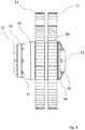
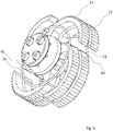
- Figure 1 shows a forward side view of a cleaning device according to an embodiment of the present invention.
- Figures 2 , 3 and 4 illustrate front, back and side views, respectively.
- the cleaning device can be used in pipe rehabilitation work to clean the pipes and to remove unwanted material, especially a collapsed liner, from the pipes.
- the cleaning device comprises a body having a front body member 30 and a back body member 50 that has a connector 53, 54 for a drive shaft.
- the front body member 30 has apertures 31 or recesses defined therein and the back body member 50 has apertures 51 or recesses defined therein.
- Pins 16 are accommodated in said apertures or recesses of the front body member and back body member.
- the pins 16 extend between the front body member and back body member.
- the pins have preferably a circular cross-section.
- the body is preferably made of a metal, such as aluminium, iron or steel.
- the body may comprise multiple parts fixed together e.g. with screws and/or bolts and nuts.
- the connector 53, 54 is preferably a socket 53 that has a slightly larger diameter than the drive shaft.
- two or more threaded apertures 54 are provided on the side of the socket for accommodating tightening screws.
- a quick lock connector can be used.
- the connector is provided on a reverse side of the back body member of the cleaning device so that the cleaning device can be pushed forward in a pipe by pushing the drive shaft into the pipe.
- An end of the drive shaft is inserted into the socket and the drive shaft is secured to the connector by tightening the tightening screws against the drive shaft.
- the drive shaft is preferably made of a steel cable or similar flexible drive shaft that has some flexibility to be able to bend through bends of a pipeline.
- the cleaning device can be operated by rotating the drive shaft.
- the rotation of the drive shaft rotates the body of the cleaning device around a rotation axis RA illustrated in Figure 1 .
- a powerful electric motor or a hydraulic motor can be used for rotating the drive shaft.
- electric motors that have an output of 2 to 10 kW and operating in a range of 500 to 2,500 rpm can be used with cleaning devices that have a diameter from about 50 mm to about 300 mm. It is understood that the diameter may be less than 50 mm and more than 300 mm also.
- the cleaning device comprises a first set of grinding cutters 11 pivotally attached to the pins 16 of the body.
- the cutters have an aperture defined therein and extending through the cutters for accommodating the pins 16 for allowing pivotal movement of the cutters.
- the pivotal connection allows movement of a cutter in a plane perpendicular to the rotation axis RA.
- the cutters can therefore turn to increase or decrease diameter of the cleaning device.
- the cutters have cutting edges on their long outer surface from the rotation axis RA. Said cutting edges are preferable parallel to the rotation axis to prevent causing a pushing force or a pulling force on the device while rotating. In an embodiment said cutting edges are not parallel to the rotation axis in order to exert a pushing force or a pulling force on the device while rotating.
- Said cutting edges are provided on the cutter surface by cutting oval arcs, circular arcs, quadratic notches or other recesses on the surface of the cutter.
- pieces of metal preferably hard metal, can be fixed to the cutter for providing cutting edges.
- the cutters have preferably a curved shaped and the cutting edges are provided on a convex surface whereas the opposing concave surface faces towards the body of the cleaning device.
- the curved shape of the cutters better adaptation to changing diameter of a pipe and also divides the cleaning action to a larger number of cutting edges.
- Cutting edges can be provided in various angles in relation to radial direction from the rotation axis. This angle defines how aggressively the cutting edges cut the material they hit onto in the pipe.
- the radial direction would be 0° in which the cutting edge points in a direction straight out from the rotation axis.
- a leading cutting edge is inclined towards the direction of rotation and it tends to dig into the material.
- the leading cutting edge is aggressive and effective and therefore suitable for removing hard materials.
- the leading cutting edge may cut too deep and get jammed or stuck in to the material if it's soft and/or resilient as the leading edge design cuts into the material.
- a trailing cutting edge on the other hand is inclined away from the direction of rotation. It could be described as sweeping the surface instead of cutting into it.
- the trailing cutting edge is suitable for removing softer materials and for performing general cleaning of small residues.
- a cutter having the trailing cutting edges is safe to use because there is no risk of jamming.
- FIG. 5 shows a forward side view of a cleaning device according to an embodiment wherein said turning of cutters against the body is facilitated with elastic force.
- a guide pin 61, 62 is provided on each cutter.
- Elastic bands 71, 72 are strapped around the guide pins 61, 62 in such a way that one elastic band surrounds guide pins of all the cutters of a set of cutters.
- the elastic band stretches when the cleaning device rotates with high enough speed and cutters turn away from the body. When the rotation is stopped, the elastic band contracts and turns the cutters towards the body.
- the pivotally connected cutters are arranged to change diameter of the cleaning device by at least 20%, 25% or 30% between extreme positions of pivotal motion of the pivotally connected cutters.
- the cleaning device can fit through a hole having diameter of 125 mm when the cutters are against the body but the same cleaning device can clean a pipe having diameter of 225 mm when the cleaning device is rotated and the cutters have fully turned away from the body.
- the cleaning device comprises a second set of cutters 12 and a spacer 40 provided between cutters of the first set of cutters and the second set of cutters.
- the spacer is preferably disc-shaped and the spacer 40 has apertures defined therein for accommodating the pins 16.
- the spacer defines a gap between the first set of cutters 11 and the second set of cutters 12 thereby allowing cutters to move individually and preventing the cutters of the first set of cutters and the cutters of the second set of cutters from hitting each other.
- the second set of cutters stabilizes the cleaning device and helps in maintaining the rotation axis of the cleaning device in same direction as the pipe.
- the second set of cutters also increases the surface area that is being cleaned at a time.
- the second set of cutters 12 consists of larger or smaller cutters than the first set of cutters 11.
- Smaller cutters near the front body member facilitate entering into a smaller cavity and the smaller cutters can enlarge the cavity so that the larger cutters near the back body member can enter the cavity and remove and remaining material in that particular section of the pipe.
- the cleaning device comprises multiple sets of cutters having spacers provided between each set of cutters. The size of the cutters between the sets of cutters remains the same or increases between each subsequent set of cutters in a direction from the front body member towards the back body member. This way entering into small cavities is facilitated and/or the surface area that is being cleaned at a time increases.
- the cleaning device has apertures 31 defined in the front body member 30 extending through the front body member 30 thereby allowing removal of the pins 16 and the cutters 11.
- the cleaning device further comprises a removable front plate 20 attached to the front body member 30, e.g. with screws or bolts.
- the front plate at least partially covering said apertures 31 for securing the pins 16.
- the cutters can be changed by removing the front plate 20 and removing the pins 16 and thereby releasing the cutters. New cutters can be placed in and the pins are inserted through the apertures of the front body member and through the apertures of the cutters into the apertures or recesses of the back body member and then attaching the front plate back onto the front body member for locking the pins in again.
- the front plate 20 can be substituted with a cutting panel, grinding panel or sanding panel for removing material from a pipe when the cleaning device is pushed forward in the pipe.
- Said panel preferably removes material and defines a cavity in which the first set of cutters can be inserted for widening the cavity with the cutters and ultimately cleaning the pipe.
- Said panel can also be attached to the tool in addition to the front panel 20.
- the cleaning device comprises a centering device for centering the cleaning device within a pipe.
- a set of cutters 11, 12 can be a centering device.
- the centering device comprises a body having stiff brushes radially extending from the body for centering the cleaning device within the pipe.
- the body of the centering device preferably surrounds the body of the cleaning device or the shaft.
- the body of the centering device preferably comprises bearings for eliminating or decreasing transmission of rotary motion of the shaft or the body of the cleaning device to the centering device to prevent wearing of the brushes.
- the brushes point radially out from the body of the centering device and the brushes are preferably configured to reach the inner surface of the pipe around the pipe.
- the centering device can be located along the rotational axis of the cleaning device in front and/or behind the front body member and/or back body member. In an embodiment the centering device is located along the rotational axis of the cleaning device on both sides of a set of cutters.
Landscapes
- Engineering & Computer Science (AREA)
- Mechanical Engineering (AREA)
- General Engineering & Computer Science (AREA)
- Chemical & Material Sciences (AREA)
- Combustion & Propulsion (AREA)
- Health & Medical Sciences (AREA)
- Life Sciences & Earth Sciences (AREA)
- Hydrology & Water Resources (AREA)
- Public Health (AREA)
- Water Supply & Treatment (AREA)
- Cleaning In General (AREA)
Applications Claiming Priority (1)
| Application Number | Priority Date | Filing Date | Title |
|---|---|---|---|
| FI20165641A FI127001B (en) | 2016-08-26 | 2016-08-26 | Pipe cleaning device |
Publications (2)
| Publication Number | Publication Date |
|---|---|
| EP3287201A1 true EP3287201A1 (fr) | 2018-02-28 |
| EP3287201B1 EP3287201B1 (fr) | 2022-04-20 |
Family
ID=59655912
Family Applications (1)
| Application Number | Title | Priority Date | Filing Date |
|---|---|---|---|
| EP17186261.8A Active EP3287201B1 (fr) | 2016-08-26 | 2017-08-15 | Dispositif de nettoyage de tuyau |
Country Status (3)
| Country | Link |
|---|---|
| US (1) | US20180056342A1 (fr) |
| EP (1) | EP3287201B1 (fr) |
| FI (1) | FI127001B (fr) |
Cited By (1)
| Publication number | Priority date | Publication date | Assignee | Title |
|---|---|---|---|---|
| EP3617414A1 (fr) * | 2018-09-03 | 2020-03-04 | Boldan Oy | Foret à lame de nettoyage de tuyaux ou de dispositif d'ouverture |
Citations (3)
| Publication number | Priority date | Publication date | Assignee | Title |
|---|---|---|---|---|
| GB190919259A (en) * | 1909-08-21 | 1910-04-28 | Joseph James Allen | A New or Improved Cutter-head or Cutting Tool for Pipe Cleaning Machines. |
| GB842332A (en) * | 1957-03-26 | 1960-07-27 | James Victor Ronaldson | Tools for the abrasive treatment of the interior of hollow bodies |
| WO1995024980A1 (fr) * | 1994-03-16 | 1995-09-21 | Helmar Haas | Dispositif permettant d'eliminer des objets saillants a l'interieur d'un conduit |
Family Cites Families (14)
| Publication number | Priority date | Publication date | Assignee | Title |
|---|---|---|---|---|
| US766712A (en) * | 1903-06-19 | 1904-08-02 | Charles E Lloyd | Boiler tube and flue scraper. |
| US910183A (en) * | 1905-10-10 | 1909-01-19 | Andrew H Dreijer | Boiler-cleaner. |
| US1163661A (en) * | 1914-09-19 | 1915-12-14 | Lagonda Mfg Co | Tube-cleaner. |
| US1370769A (en) * | 1918-02-05 | 1921-03-08 | Rotary Scraper Company Inc | Percussive implement |
| US1856299A (en) * | 1930-10-16 | 1932-05-03 | Johannes Cornelis Van Alphen | Scaling device |
| US2164689A (en) * | 1937-10-12 | 1939-07-04 | Chester L Shobe | Tube and pipe cleaner |
| CH490900A (de) * | 1967-06-28 | 1970-05-31 | Arx Paul Von | Vorrichtung, mit deren Hilfe die Innenwand eines Rohres gereinigt und/oder mit einem Schutzanstrich versehen werden kann |
| DE2723547C2 (de) * | 1977-05-25 | 1983-10-20 | Otto Junker Gmbh, 5107 Simmerath | Vorrichtung zum Entfernen der Schlackenansätze sowie infiltrierten inneren Randschichten an Schmelz- oder Gießgefäßen |
| US6467121B1 (en) * | 2000-08-15 | 2002-10-22 | Goodway Technologies Corporation | Rotary tube scrubber |
| US7121336B2 (en) * | 2002-11-11 | 2006-10-17 | Mcginnis Chemical, Inc | Well scrubber |
| CA2530932C (fr) * | 2005-12-20 | 2013-08-13 | Pii (Canada) Limited | Dispositif pour nettoyer les pipelines multidiametres |
| US20100294316A1 (en) * | 2009-05-20 | 2010-11-25 | Itc, Inc. | Tube Cleaning Device |
| US9662690B2 (en) * | 2014-07-15 | 2017-05-30 | Chevron U.S.A. Inc. | Systems for maintaining a functional line for conveying fluid and pig assemblies for use therein |
| CA2934339C (fr) * | 2015-07-01 | 2019-02-12 | Fer-Pal Construction Ltd. | Systeme de retrait de revetement interieur |
-
2016
- 2016-08-26 FI FI20165641A patent/FI127001B/en active IP Right Grant
-
2017
- 2017-08-15 EP EP17186261.8A patent/EP3287201B1/fr active Active
- 2017-08-15 US US15/677,124 patent/US20180056342A1/en not_active Abandoned
Patent Citations (3)
| Publication number | Priority date | Publication date | Assignee | Title |
|---|---|---|---|---|
| GB190919259A (en) * | 1909-08-21 | 1910-04-28 | Joseph James Allen | A New or Improved Cutter-head or Cutting Tool for Pipe Cleaning Machines. |
| GB842332A (en) * | 1957-03-26 | 1960-07-27 | James Victor Ronaldson | Tools for the abrasive treatment of the interior of hollow bodies |
| WO1995024980A1 (fr) * | 1994-03-16 | 1995-09-21 | Helmar Haas | Dispositif permettant d'eliminer des objets saillants a l'interieur d'un conduit |
Cited By (1)
| Publication number | Priority date | Publication date | Assignee | Title |
|---|---|---|---|---|
| EP3617414A1 (fr) * | 2018-09-03 | 2020-03-04 | Boldan Oy | Foret à lame de nettoyage de tuyaux ou de dispositif d'ouverture |
Also Published As
| Publication number | Publication date |
|---|---|
| EP3287201B1 (fr) | 2022-04-20 |
| FI127001B (en) | 2017-09-15 |
| FI20165641A7 (fi) | 2017-09-15 |
| US20180056342A1 (en) | 2018-03-01 |
Similar Documents
| Publication | Publication Date | Title |
|---|---|---|
| JP6687926B2 (ja) | パイプの内面を洗浄するための装置 | |
| EP2934774B1 (fr) | Dispositif de nettoyage de conduites | |
| JP5585895B2 (ja) | パイプ系統の改修のための工具と方法 | |
| US5056176A (en) | Cutter assembly for rotary drain cleaner | |
| EP3287201A1 (fr) | Dispositif de nettoyage de tuyau | |
| KR101051562B1 (ko) | 노후화된 상수도관 내경의 콜탈에나멜 및 내부도장재 제거장치 | |
| US11040382B2 (en) | Adaptive cleaning device | |
| CN107671087B (zh) | 一种电力施工线缆铺设管路疏通装置 | |
| US20190329303A1 (en) | Device for cleaning inner surface of pipe | |
| US6058547A (en) | Device for removing objects from enclosed areas | |
| US10427223B2 (en) | Device for opening connection to lined pipe | |
| US7052554B2 (en) | Spring shaft for pipe cleaning apparatus | |
| US20190022715A1 (en) | Cleaning device for cleaning of pipes | |
| US2628380A (en) | Expansible pipe-cleaning knife | |
| US20170368581A1 (en) | Cleaning device | |
| US20170361417A1 (en) | Grinding device | |
| JP6970710B2 (ja) | エンドミル | |
| EP3105491B1 (fr) | Dispositif et système permettant d'ouvrir un point de ramification d'ensemble conduit | |
| SE541720C2 (en) | Cleaning device for cleaning of pipes | |
| JPH01121114A (ja) | カッター | |
| JP2000145369A (ja) | 既設管の撤去工法 |
Legal Events
| Date | Code | Title | Description |
|---|---|---|---|
| PUAI | Public reference made under article 153(3) epc to a published international application that has entered the european phase |
Free format text: ORIGINAL CODE: 0009012 |
|
| STAA | Information on the status of an ep patent application or granted ep patent |
Free format text: STATUS: THE APPLICATION HAS BEEN PUBLISHED |
|
| AK | Designated contracting states |
Kind code of ref document: A1 Designated state(s): AL AT BE BG CH CY CZ DE DK EE ES FI FR GB GR HR HU IE IS IT LI LT LU LV MC MK MT NL NO PL PT RO RS SE SI SK SM TR |
|
| AX | Request for extension of the european patent |
Extension state: BA ME |
|
| STAA | Information on the status of an ep patent application or granted ep patent |
Free format text: STATUS: REQUEST FOR EXAMINATION WAS MADE |
|
| 17P | Request for examination filed |
Effective date: 20180828 |
|
| RBV | Designated contracting states (corrected) |
Designated state(s): AL AT BE BG CH CY CZ DE DK EE ES FI FR GB GR HR HU IE IS IT LI LT LU LV MC MK MT NL NO PL PT RO RS SE SI SK SM TR |
|
| GRAP | Despatch of communication of intention to grant a patent |
Free format text: ORIGINAL CODE: EPIDOSNIGR1 |
|
| STAA | Information on the status of an ep patent application or granted ep patent |
Free format text: STATUS: GRANT OF PATENT IS INTENDED |
|
| INTG | Intention to grant announced |
Effective date: 20211117 |
|
| GRAS | Grant fee paid |
Free format text: ORIGINAL CODE: EPIDOSNIGR3 |
|
| GRAA | (expected) grant |
Free format text: ORIGINAL CODE: 0009210 |
|
| STAA | Information on the status of an ep patent application or granted ep patent |
Free format text: STATUS: THE PATENT HAS BEEN GRANTED |
|
| AK | Designated contracting states |
Kind code of ref document: B1 Designated state(s): AL AT BE BG CH CY CZ DE DK EE ES FI FR GB GR HR HU IE IS IT LI LT LU LV MC MK MT NL NO PL PT RO RS SE SI SK SM TR |
|
| REG | Reference to a national code |
Ref country code: GB Ref legal event code: FG4D |
|
| REG | Reference to a national code |
Ref country code: CH Ref legal event code: EP |
|
| REG | Reference to a national code |
Ref country code: IE Ref legal event code: FG4D |
|
| REG | Reference to a national code |
Ref country code: DE Ref legal event code: R096 Ref document number: 602017056166 Country of ref document: DE |
|
| REG | Reference to a national code |
Ref country code: AT Ref legal event code: REF Ref document number: 1484763 Country of ref document: AT Kind code of ref document: T Effective date: 20220515 |
|
| REG | Reference to a national code |
Ref country code: LT Ref legal event code: MG9D |
|
| REG | Reference to a national code |
Ref country code: NL Ref legal event code: MP Effective date: 20220420 |
|
| REG | Reference to a national code |
Ref country code: AT Ref legal event code: MK05 Ref document number: 1484763 Country of ref document: AT Kind code of ref document: T Effective date: 20220420 |
|
| PG25 | Lapsed in a contracting state [announced via postgrant information from national office to epo] |
Ref country code: NL Free format text: LAPSE BECAUSE OF FAILURE TO SUBMIT A TRANSLATION OF THE DESCRIPTION OR TO PAY THE FEE WITHIN THE PRESCRIBED TIME-LIMIT Effective date: 20220420 |
|
| PG25 | Lapsed in a contracting state [announced via postgrant information from national office to epo] |
Ref country code: SE Free format text: LAPSE BECAUSE OF FAILURE TO SUBMIT A TRANSLATION OF THE DESCRIPTION OR TO PAY THE FEE WITHIN THE PRESCRIBED TIME-LIMIT Effective date: 20220420 Ref country code: PT Free format text: LAPSE BECAUSE OF FAILURE TO SUBMIT A TRANSLATION OF THE DESCRIPTION OR TO PAY THE FEE WITHIN THE PRESCRIBED TIME-LIMIT Effective date: 20220822 Ref country code: NO Free format text: LAPSE BECAUSE OF FAILURE TO SUBMIT A TRANSLATION OF THE DESCRIPTION OR TO PAY THE FEE WITHIN THE PRESCRIBED TIME-LIMIT Effective date: 20220720 Ref country code: LT Free format text: LAPSE BECAUSE OF FAILURE TO SUBMIT A TRANSLATION OF THE DESCRIPTION OR TO PAY THE FEE WITHIN THE PRESCRIBED TIME-LIMIT Effective date: 20220420 Ref country code: HR Free format text: LAPSE BECAUSE OF FAILURE TO SUBMIT A TRANSLATION OF THE DESCRIPTION OR TO PAY THE FEE WITHIN THE PRESCRIBED TIME-LIMIT Effective date: 20220420 Ref country code: GR Free format text: LAPSE BECAUSE OF FAILURE TO SUBMIT A TRANSLATION OF THE DESCRIPTION OR TO PAY THE FEE WITHIN THE PRESCRIBED TIME-LIMIT Effective date: 20220721 Ref country code: FI Free format text: LAPSE BECAUSE OF FAILURE TO SUBMIT A TRANSLATION OF THE DESCRIPTION OR TO PAY THE FEE WITHIN THE PRESCRIBED TIME-LIMIT Effective date: 20220420 Ref country code: ES Free format text: LAPSE BECAUSE OF FAILURE TO SUBMIT A TRANSLATION OF THE DESCRIPTION OR TO PAY THE FEE WITHIN THE PRESCRIBED TIME-LIMIT Effective date: 20220420 Ref country code: BG Free format text: LAPSE BECAUSE OF FAILURE TO SUBMIT A TRANSLATION OF THE DESCRIPTION OR TO PAY THE FEE WITHIN THE PRESCRIBED TIME-LIMIT Effective date: 20220720 Ref country code: AT Free format text: LAPSE BECAUSE OF FAILURE TO SUBMIT A TRANSLATION OF THE DESCRIPTION OR TO PAY THE FEE WITHIN THE PRESCRIBED TIME-LIMIT Effective date: 20220420 |
|
| PG25 | Lapsed in a contracting state [announced via postgrant information from national office to epo] |
Ref country code: RS Free format text: LAPSE BECAUSE OF FAILURE TO SUBMIT A TRANSLATION OF THE DESCRIPTION OR TO PAY THE FEE WITHIN THE PRESCRIBED TIME-LIMIT Effective date: 20220420 Ref country code: PL Free format text: LAPSE BECAUSE OF FAILURE TO SUBMIT A TRANSLATION OF THE DESCRIPTION OR TO PAY THE FEE WITHIN THE PRESCRIBED TIME-LIMIT Effective date: 20220420 Ref country code: LV Free format text: LAPSE BECAUSE OF FAILURE TO SUBMIT A TRANSLATION OF THE DESCRIPTION OR TO PAY THE FEE WITHIN THE PRESCRIBED TIME-LIMIT Effective date: 20220420 Ref country code: IS Free format text: LAPSE BECAUSE OF FAILURE TO SUBMIT A TRANSLATION OF THE DESCRIPTION OR TO PAY THE FEE WITHIN THE PRESCRIBED TIME-LIMIT Effective date: 20220820 |
|
| REG | Reference to a national code |
Ref country code: DE Ref legal event code: R097 Ref document number: 602017056166 Country of ref document: DE |
|
| PG25 | Lapsed in a contracting state [announced via postgrant information from national office to epo] |
Ref country code: SM Free format text: LAPSE BECAUSE OF FAILURE TO SUBMIT A TRANSLATION OF THE DESCRIPTION OR TO PAY THE FEE WITHIN THE PRESCRIBED TIME-LIMIT Effective date: 20220420 Ref country code: SK Free format text: LAPSE BECAUSE OF FAILURE TO SUBMIT A TRANSLATION OF THE DESCRIPTION OR TO PAY THE FEE WITHIN THE PRESCRIBED TIME-LIMIT Effective date: 20220420 Ref country code: RO Free format text: LAPSE BECAUSE OF FAILURE TO SUBMIT A TRANSLATION OF THE DESCRIPTION OR TO PAY THE FEE WITHIN THE PRESCRIBED TIME-LIMIT Effective date: 20220420 Ref country code: EE Free format text: LAPSE BECAUSE OF FAILURE TO SUBMIT A TRANSLATION OF THE DESCRIPTION OR TO PAY THE FEE WITHIN THE PRESCRIBED TIME-LIMIT Effective date: 20220420 Ref country code: DK Free format text: LAPSE BECAUSE OF FAILURE TO SUBMIT A TRANSLATION OF THE DESCRIPTION OR TO PAY THE FEE WITHIN THE PRESCRIBED TIME-LIMIT Effective date: 20220420 Ref country code: CZ Free format text: LAPSE BECAUSE OF FAILURE TO SUBMIT A TRANSLATION OF THE DESCRIPTION OR TO PAY THE FEE WITHIN THE PRESCRIBED TIME-LIMIT Effective date: 20220420 |
|
| PLBE | No opposition filed within time limit |
Free format text: ORIGINAL CODE: 0009261 |
|
| STAA | Information on the status of an ep patent application or granted ep patent |
Free format text: STATUS: NO OPPOSITION FILED WITHIN TIME LIMIT |
|
| 26N | No opposition filed |
Effective date: 20230123 |
|
| PG25 | Lapsed in a contracting state [announced via postgrant information from national office to epo] |
Ref country code: MC Free format text: LAPSE BECAUSE OF FAILURE TO SUBMIT A TRANSLATION OF THE DESCRIPTION OR TO PAY THE FEE WITHIN THE PRESCRIBED TIME-LIMIT Effective date: 20220420 Ref country code: AL Free format text: LAPSE BECAUSE OF FAILURE TO SUBMIT A TRANSLATION OF THE DESCRIPTION OR TO PAY THE FEE WITHIN THE PRESCRIBED TIME-LIMIT Effective date: 20220420 |
|
| REG | Reference to a national code |
Ref country code: CH Ref legal event code: PL |
|
| PG25 | Lapsed in a contracting state [announced via postgrant information from national office to epo] |
Ref country code: LU Free format text: LAPSE BECAUSE OF NON-PAYMENT OF DUE FEES Effective date: 20220815 Ref country code: LI Free format text: LAPSE BECAUSE OF NON-PAYMENT OF DUE FEES Effective date: 20220831 Ref country code: CH Free format text: LAPSE BECAUSE OF NON-PAYMENT OF DUE FEES Effective date: 20220831 |
|
| REG | Reference to a national code |
Ref country code: BE Ref legal event code: MM Effective date: 20220831 |
|
| PG25 | Lapsed in a contracting state [announced via postgrant information from national office to epo] |
Ref country code: SI Free format text: LAPSE BECAUSE OF FAILURE TO SUBMIT A TRANSLATION OF THE DESCRIPTION OR TO PAY THE FEE WITHIN THE PRESCRIBED TIME-LIMIT Effective date: 20220420 |
|
| PG25 | Lapsed in a contracting state [announced via postgrant information from national office to epo] |
Ref country code: IE Free format text: LAPSE BECAUSE OF NON-PAYMENT OF DUE FEES Effective date: 20220815 Ref country code: FR Free format text: LAPSE BECAUSE OF NON-PAYMENT OF DUE FEES Effective date: 20220831 |
|
| PG25 | Lapsed in a contracting state [announced via postgrant information from national office to epo] |
Ref country code: BE Free format text: LAPSE BECAUSE OF NON-PAYMENT OF DUE FEES Effective date: 20220831 |
|
| PG25 | Lapsed in a contracting state [announced via postgrant information from national office to epo] |
Ref country code: IT Free format text: LAPSE BECAUSE OF FAILURE TO SUBMIT A TRANSLATION OF THE DESCRIPTION OR TO PAY THE FEE WITHIN THE PRESCRIBED TIME-LIMIT Effective date: 20220420 |
|
| PG25 | Lapsed in a contracting state [announced via postgrant information from national office to epo] |
Ref country code: HU Free format text: LAPSE BECAUSE OF FAILURE TO SUBMIT A TRANSLATION OF THE DESCRIPTION OR TO PAY THE FEE WITHIN THE PRESCRIBED TIME-LIMIT; INVALID AB INITIO Effective date: 20170815 |
|
| PG25 | Lapsed in a contracting state [announced via postgrant information from national office to epo] |
Ref country code: CY Free format text: LAPSE BECAUSE OF FAILURE TO SUBMIT A TRANSLATION OF THE DESCRIPTION OR TO PAY THE FEE WITHIN THE PRESCRIBED TIME-LIMIT Effective date: 20220420 |
|
| PG25 | Lapsed in a contracting state [announced via postgrant information from national office to epo] |
Ref country code: MK Free format text: LAPSE BECAUSE OF FAILURE TO SUBMIT A TRANSLATION OF THE DESCRIPTION OR TO PAY THE FEE WITHIN THE PRESCRIBED TIME-LIMIT Effective date: 20220420 |
|
| PG25 | Lapsed in a contracting state [announced via postgrant information from national office to epo] |
Ref country code: MT Free format text: LAPSE BECAUSE OF FAILURE TO SUBMIT A TRANSLATION OF THE DESCRIPTION OR TO PAY THE FEE WITHIN THE PRESCRIBED TIME-LIMIT Effective date: 20220420 |
|
| PG25 | Lapsed in a contracting state [announced via postgrant information from national office to epo] |
Ref country code: BG Free format text: LAPSE BECAUSE OF FAILURE TO SUBMIT A TRANSLATION OF THE DESCRIPTION OR TO PAY THE FEE WITHIN THE PRESCRIBED TIME-LIMIT Effective date: 20220420 |
|
| PG25 | Lapsed in a contracting state [announced via postgrant information from national office to epo] |
Ref country code: BG Free format text: LAPSE BECAUSE OF FAILURE TO SUBMIT A TRANSLATION OF THE DESCRIPTION OR TO PAY THE FEE WITHIN THE PRESCRIBED TIME-LIMIT Effective date: 20220420 |
|
| PGFP | Annual fee paid to national office [announced via postgrant information from national office to epo] |
Ref country code: DE Payment date: 20250820 Year of fee payment: 9 |
|
| PGFP | Annual fee paid to national office [announced via postgrant information from national office to epo] |
Ref country code: GB Payment date: 20250821 Year of fee payment: 9 |
|
| PG25 | Lapsed in a contracting state [announced via postgrant information from national office to epo] |
Ref country code: TR Free format text: LAPSE BECAUSE OF FAILURE TO SUBMIT A TRANSLATION OF THE DESCRIPTION OR TO PAY THE FEE WITHIN THE PRESCRIBED TIME-LIMIT Effective date: 20220420 |