EP3287231A1 - Dispositif de changement d'outil et centre d'usinage doté d'un dispositif de changement d'outil - Google Patents
Dispositif de changement d'outil et centre d'usinage doté d'un dispositif de changement d'outil Download PDFInfo
- Publication number
- EP3287231A1 EP3287231A1 EP17020331.9A EP17020331A EP3287231A1 EP 3287231 A1 EP3287231 A1 EP 3287231A1 EP 17020331 A EP17020331 A EP 17020331A EP 3287231 A1 EP3287231 A1 EP 3287231A1
- Authority
- EP
- European Patent Office
- Prior art keywords
- tool
- leg
- pivot bearing
- changing device
- support arm
- Prior art date
- Legal status (The legal status is an assumption and is not a legal conclusion. Google has not performed a legal analysis and makes no representation as to the accuracy of the status listed.)
- Granted
Links
Images



Classifications
-
- B—PERFORMING OPERATIONS; TRANSPORTING
- B23—MACHINE TOOLS; METAL-WORKING NOT OTHERWISE PROVIDED FOR
- B23Q—DETAILS, COMPONENTS, OR ACCESSORIES FOR MACHINE TOOLS, e.g. ARRANGEMENTS FOR COPYING OR CONTROLLING; MACHINE TOOLS IN GENERAL CHARACTERISED BY THE CONSTRUCTION OF PARTICULAR DETAILS OR COMPONENTS; COMBINATIONS OR ASSOCIATIONS OF METAL-WORKING MACHINES, NOT DIRECTED TO A PARTICULAR RESULT
- B23Q3/00—Devices holding, supporting, or positioning work or tools, of a kind normally removable from the machine
- B23Q3/155—Arrangements for automatic insertion or removal of tools, e.g. combined with manual handling
- B23Q3/1552—Arrangements for automatic insertion or removal of tools, e.g. combined with manual handling parts of devices for automatically inserting or removing tools
- B23Q3/1554—Transfer mechanisms, e.g. tool gripping arms; Drive mechanisms therefore
-
- B—PERFORMING OPERATIONS; TRANSPORTING
- B23—MACHINE TOOLS; METAL-WORKING NOT OTHERWISE PROVIDED FOR
- B23Q—DETAILS, COMPONENTS, OR ACCESSORIES FOR MACHINE TOOLS, e.g. ARRANGEMENTS FOR COPYING OR CONTROLLING; MACHINE TOOLS IN GENERAL CHARACTERISED BY THE CONSTRUCTION OF PARTICULAR DETAILS OR COMPONENTS; COMBINATIONS OR ASSOCIATIONS OF METAL-WORKING MACHINES, NOT DIRECTED TO A PARTICULAR RESULT
- B23Q3/00—Devices holding, supporting, or positioning work or tools, of a kind normally removable from the machine
- B23Q3/155—Arrangements for automatic insertion or removal of tools, e.g. combined with manual handling
- B23Q3/157—Arrangements for automatic insertion or removal of tools, e.g. combined with manual handling of rotary tools
- B23Q3/15713—Arrangements for automatic insertion or removal of tools, e.g. combined with manual handling of rotary tools a transfer device taking a single tool from a storage device and inserting it in a spindle
- B23Q3/1572—Arrangements for automatic insertion or removal of tools, e.g. combined with manual handling of rotary tools a transfer device taking a single tool from a storage device and inserting it in a spindle the storage device comprising rotating or circulating storing means
- B23Q3/15724—Chains or belts
-
- B—PERFORMING OPERATIONS; TRANSPORTING
- B23—MACHINE TOOLS; METAL-WORKING NOT OTHERWISE PROVIDED FOR
- B23Q—DETAILS, COMPONENTS, OR ACCESSORIES FOR MACHINE TOOLS, e.g. ARRANGEMENTS FOR COPYING OR CONTROLLING; MACHINE TOOLS IN GENERAL CHARACTERISED BY THE CONSTRUCTION OF PARTICULAR DETAILS OR COMPONENTS; COMBINATIONS OR ASSOCIATIONS OF METAL-WORKING MACHINES, NOT DIRECTED TO A PARTICULAR RESULT
- B23Q3/00—Devices holding, supporting, or positioning work or tools, of a kind normally removable from the machine
- B23Q3/155—Arrangements for automatic insertion or removal of tools, e.g. combined with manual handling
- B23Q3/157—Arrangements for automatic insertion or removal of tools, e.g. combined with manual handling of rotary tools
- B23Q3/15713—Arrangements for automatic insertion or removal of tools, e.g. combined with manual handling of rotary tools a transfer device taking a single tool from a storage device and inserting it in a spindle
- B23Q3/1572—Arrangements for automatic insertion or removal of tools, e.g. combined with manual handling of rotary tools a transfer device taking a single tool from a storage device and inserting it in a spindle the storage device comprising rotating or circulating storing means
- B23Q3/15753—Arrangements for automatic insertion or removal of tools, e.g. combined with manual handling of rotary tools a transfer device taking a single tool from a storage device and inserting it in a spindle the storage device comprising rotating or circulating storing means the storage means rotating or circulating in a plane perpendicular to the axis of the spindle
- B23Q3/15766—Arrangements for automatic insertion or removal of tools, e.g. combined with manual handling of rotary tools a transfer device taking a single tool from a storage device and inserting it in a spindle the storage device comprising rotating or circulating storing means the storage means rotating or circulating in a plane perpendicular to the axis of the spindle the axis of the stored tools being arranged perpendicularly to the rotating or circulating plane of the storage means
-
- B—PERFORMING OPERATIONS; TRANSPORTING
- B23—MACHINE TOOLS; METAL-WORKING NOT OTHERWISE PROVIDED FOR
- B23Q—DETAILS, COMPONENTS, OR ACCESSORIES FOR MACHINE TOOLS, e.g. ARRANGEMENTS FOR COPYING OR CONTROLLING; MACHINE TOOLS IN GENERAL CHARACTERISED BY THE CONSTRUCTION OF PARTICULAR DETAILS OR COMPONENTS; COMBINATIONS OR ASSOCIATIONS OF METAL-WORKING MACHINES, NOT DIRECTED TO A PARTICULAR RESULT
- B23Q3/00—Devices holding, supporting, or positioning work or tools, of a kind normally removable from the machine
- B23Q3/155—Arrangements for automatic insertion or removal of tools, e.g. combined with manual handling
- B23Q3/1552—Arrangements for automatic insertion or removal of tools, e.g. combined with manual handling parts of devices for automatically inserting or removing tools
- B23Q3/1554—Transfer mechanisms, e.g. tool gripping arms; Drive mechanisms therefore
- B23Q2003/155414—Transfer mechanisms, e.g. tool gripping arms; Drive mechanisms therefore the transfer mechanism comprising two or more grippers
- B23Q2003/155418—Transfer mechanisms, e.g. tool gripping arms; Drive mechanisms therefore the transfer mechanism comprising two or more grippers the grippers moving together
-
- B—PERFORMING OPERATIONS; TRANSPORTING
- B23—MACHINE TOOLS; METAL-WORKING NOT OTHERWISE PROVIDED FOR
- B23Q—DETAILS, COMPONENTS, OR ACCESSORIES FOR MACHINE TOOLS, e.g. ARRANGEMENTS FOR COPYING OR CONTROLLING; MACHINE TOOLS IN GENERAL CHARACTERISED BY THE CONSTRUCTION OF PARTICULAR DETAILS OR COMPONENTS; COMBINATIONS OR ASSOCIATIONS OF METAL-WORKING MACHINES, NOT DIRECTED TO A PARTICULAR RESULT
- B23Q3/00—Devices holding, supporting, or positioning work or tools, of a kind normally removable from the machine
- B23Q3/155—Arrangements for automatic insertion or removal of tools, e.g. combined with manual handling
- B23Q3/1552—Arrangements for automatic insertion or removal of tools, e.g. combined with manual handling parts of devices for automatically inserting or removing tools
- B23Q3/1554—Transfer mechanisms, e.g. tool gripping arms; Drive mechanisms therefore
- B23Q2003/155414—Transfer mechanisms, e.g. tool gripping arms; Drive mechanisms therefore the transfer mechanism comprising two or more grippers
- B23Q2003/155425—Transfer mechanisms, e.g. tool gripping arms; Drive mechanisms therefore the transfer mechanism comprising two or more grippers pivotable
- B23Q2003/155435—Transfer mechanisms, e.g. tool gripping arms; Drive mechanisms therefore the transfer mechanism comprising two or more grippers pivotable and linearly movable
- B23Q2003/155439—Transfer mechanisms, e.g. tool gripping arms; Drive mechanisms therefore the transfer mechanism comprising two or more grippers pivotable and linearly movable along the pivoting axis
Definitions
- the invention relates to a tool changing device for use in conjunction with a movable traveling column of a machining center for machining a workpiece by means of different tools having the features of the preamble of claim 1.
- the invention is also a machining center of this type with the features of the preamble of claim.
- Machining centers of the type in question are used in the mechanical and plant engineering of complex workpieces on up to five pages or including a Umspannvorgangs on up to six pages by means of a three-axis or five-axis machining. Both a three-axis and a five-axis machining serves a traveling column with at least one spindle.
- the traveling column is usually constructed in the manner of an X-Y-Z carriage.
- the traveling column works together with a turntable unit on which a workpiece is clamped.
- the workpiece can be completely rotated about its vertical axis relative to the spindle and, as a rule, pivot 90 ° on both sides.
- the three-axis guidance of the spindle results in the total five-axis machining capability for the clamped on the turntable of the rotary-swivel unit workpiece.
- Typical operations of a workpiece in such a machining center are reshaping, cutting and joining workpieces made of metal.
- a machining center can also be designed for machining workpieces made of plastic or wood.
- the main field of application is metal cutting such as drilling or milling.
- the spindle of the machining centers of the type in question is a tool-carrying motor spindle, ie, in the spindle, a tool is used, which is rotated by the spindle during the machining of the workpiece.
- the spindle has a tool interface.
- the tool interface includes a tool holder for receiving a tool and a tool clamp for releasably fixing the tool to the spindle.
- a change of the tool located in the spindle may be required, for. B. because a different kind of tool for further processing of the workpiece is necessary or because the tool used is defective or worn.
- an automated tool changing device is used.
- a tool changing device is used to remove a tool from the spindle, for transporting the tool to a tool magazine or tool storage, for transferring the tool to the tool magazine, for receiving another tool from the tool magazine, for transporting this other tool from the tool magazine to the spindle and to insert this other tool into the spindle.
- the chip-to-chip time has a direct influence on the machining time, ie the time for machining the workpiece or the cycle time.
- the known tool changing device reduces the chip-to-chip time by a special construction of the support arm and its drive.
- the two tool holders of the double gripper are arranged offset in this support arm in the circumferential direction of the pivoting circle to each other, but both have the same distance from the center of the pivoting circle. Based on the pivoting circle, the two tool holders are aligned open to the outside.
- a tool receptacle of the double gripper can thus be moved to the position which the other tool receptacle of the double gripper held before this pivoting.
- the spindle on the movable traveling column for changing tools must not be moved in the XY plane. Rather, only the double gripper pivots on the support arm of its first to its second tool change position. This pivoting takes less time than a spindle process.
- the support arm from the pivot bearing to the double gripper is substantially straight, although slightly cranked in the Z direction.
- the swing circle therefore has a relatively large diameter.
- the clearance in the machining center between the tool changing device and the traveling column must be correspondingly wide. Then, if a delimitation, for example, an intermediate wall is provided in this area, a passage opening in such a boundary must also be relatively wide.
- the teaching is based on the problem, the known tool changing device in such a way and further develop that it requires less space in the pivoting range of the support arm.
- the tool changing device according to the invention functions in the same way as the tool changing device known from the prior art and also has the same advantages in terms of machining speed, robustness and reliability. In that regard, so to the full extent on the disclosure of the EP 2 881 219 A1 to get expelled.
- the support arm between the pivot bearing and the double gripper is not designed substantially straight, but is executed in the plan view in the Z direction as a U-shaped arc. From the pivot bearing first goes out of the first leg of the support arm, goes into an arcuate vertex and this in turn goes into the extending to the double gripper second leg.
- the entire length of the support arm between pivot bearing and double gripper is significantly larger than the radial distance of the double gripper from the geometric pivot axis of the pivot bearing with this construction. This has various design and procedural advantages.
- the shape of the support arm is for the pivotal movement of the support arm relative to the traveling column of the machining center of considerable importance.
- the support arm is formed asymmetrically, wherein the first leg has a substantially smaller length than the second leg.
- length always means the length determined along the course of the leg along its center line.
- the first leg is substantially straight and, measured from the centerline of the first leg from the geometric pivot axis of the pivot bearing to the beginning of the arcuate vertex, has a length of 120 mm to 240 mm. preferably from 150 mm to 180 mm.
- it has a length, measured at the center line to the inflection point of the vertex, of 200 mm to 600 mm, preferably from 320 mm to 400 mm.
- Very particularly preferred is a construction of this type, in which the second leg extends arcuately with a radius of curvature decreasing from the apex to the double gripper.
- the U formed in the plan view in the Z direction acts at the end of the second leg in the amount of the double gripper retracted inward.
- a particularly interesting parameter for the tool changing device is the radius of the pivoting circle.
- the support arm of the tool changing device is constructed so that the pivoting circle, measured between the geometric pivot axis of the pivot bearing and the center of the tool holder of the double gripper, a radius of 200 mm to 400 mm, preferably from 220 mm to 380 mm, more preferably of 260 mm up to 300 mm. Since the entire length of the first and second leg of the support arm is substantially larger than the radius of the pivoting circle, the support arm has the opportunity to perform a corresponding threading movement.
- the apex has a minimum radius of curvature of 50 mm to 100 mm, preferably from 60 mm to 80 mm.
- the invention also provides a machining center having the features of the preamble of claim 7, which according to the invention by the features characterized the characterizing part of claim 7, in particular therefore by the use of a tool changing device according to the invention.
- the intermediate wall has a passage opening.
- the tool magazine with the tool changing device is arranged on the side facing away from the Maschinen commonpositionier Scheme side of the intermediate wall, the traveling column with the spindle is located on the travel guide, which extends parallel to the Maschinen commonpositionier Scheme.
- the pivot bearing of the support arm of the tool changing device is arranged according to the invention on the side remote from the Maschinen commonpositionier Scheme side near the intermediate wall next to the edge of the passage opening in the intermediate wall.
- the support arm is aligned relative to the intermediate wall so that the double gripper is pivotable from a position on the side facing away from the Maschinen commonpositionier Scheme side of the intermediate wall through the passage opening into the Maschinen commonpositionier Scheme into the spindle of the driving stand.
- the support arm Due to the U-shaped configuration of the support arm, it can be moved in an arc-shaped manner into the passage opening, which is quite narrow in accordance with the invention, and enter the workpiece positioning area therethrough.
- the passage opening can be significantly narrower than in the substantially straight support arm of the above-described prior art.
- first leg, the vertex and a part of the second leg of the support arm remain on the side of the intermediate wall facing the pivot bearing, even with the support arm pivoted as far as possible.
- the distance of the edge of the passage opening or in the presence of a movable closure of the edge of the open closure of the geometric pivot axis of the pivot bearing between 95% and 80% of the length of the first leg, measured at the center line of the first leg from the geometric pivot axis of the pivot bearing to the beginning of the arcuate vertex is.
- Fig. 1 The machining center shown is in itself known in its basic structure (EP 2 370 230 B1 ; EP 2 881 219 A1 ). Such a machining center initially has a machine base 1, to which a circumferential protective covering 2 is attached. In order to be able to recognize the interior of the machining center, the protective covering 2 has been cut off relatively far down here. This is the inner workings of the machining center in Fig. 1 clearly visible.
- the machine base 1 defines with its horizontal longitudinal orientation an X-axis or X-direction, in Fig. 1 from left to right, with its horizontal Transverse orientation a Y-axis or Y-direction, in Fig. 1 from front to back into the plane of the drawing and with its vertical orientation a Z-axis or Z-direction, in Fig. 1 from top to bottom.
- Fig. 1 can be seen at the front of the machine base 1 in the protective lining a feed opening 3.
- the feed opening 3 is regularly closed by a protective door, but in Fig. 1 has been omitted for illustrative reasons.
- Fig. 1 one sees on the left behind the workpiece positioning region 4 a traverse guide 6, likewise extending in the X direction, on which a traveling column 7 can be moved back and forth in the X direction parallel to the workpiece positioning region 4.
- the traveling column 7 carries a tool-carrying, in turn again movable spindle 8.
- Fig. 1 is in the spindle 8 no tool used.
- a tool magazine 9 which is fixedly arranged here on the machine base support 1 and has a plurality of tool holders 10 for various individual tools 11.
- a single such tool 11 is in Fig. 1 indicated on the right.
- a tool changing device 12 with which in each case a tool 11 can be transported from the tool magazine 10 to the movable spindle 8 mounted on the traveling column 7 and back.
- the support arm 15 has at its other end a double gripper 18 with two tool holders 19.
- the pivot bearing 14 more precisely driven by the pivot drive 16 on the pivot bearing 14, the support arm 15 about the vertical pivot axis 17 is pivotable.
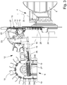
- the tool holders 19 of the double gripper 18 on a horizontal pivoting circuit 20 which in Fig. 3 indicated by the dot-dash line.
- the two tool holders 19 of the double gripper 18 are also arranged offset in the circumferential direction of the pivoting circle 20 here. They are based on the pivoting circle 20 radially outwardly aligned and here both have the same distance to the center of the pivoting circuit 20, so the geometric pivot axis 17. This has regard to the processes explained in detail above advantages.
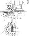
- the invention provides that the support arm 15 is executed between the pivot bearing 14 and the double gripper 18 in plan view in the Z direction as a U-shaped arc with an outgoing from the pivot bearing 14 first leg 21, the formation of a arcuate apex 22 merges into a to the double gripper 18 extending second leg 23.
- the support arm 15 is thus not, as in the prior art, executed in the plan view in the Z direction substantially straight, but he is angled, and here according to the preferred teaching asymmetric, wherein the first leg 21 has a much smaller length than the second Leg 23 has.
- the definition of the "length” in this case is to be understood as meaning that the center line of the respective limb 21, 23 is selected and the length is determined along its course, if necessary also in the form of an arc.
- Fig. 5 shows particularly well how in the preferred embodiment, which is shown here, the exact course of the support arm 15 is provided. It is shown that the first leg 21 is substantially straight. Measured at the center line of the first leg 21, from the geometric pivot axis of the pivot bearing 14 to the beginning of the arcuate crest 22, here it has a length of, for example, about 160 mm.
- the second leg 23 extends here arcuately. He has here in the illustrated and preferred embodiment, a length, here measured at the center line of the second leg 23, but up to the inflection point of the apex 22, since the transition between the second leg 23 and vertex 22 is flowing, of about 330 mm.
- the radius of curvature of the second leg 23 is reduced from the apex 22 to the double gripper 18.
- the second leg 23 of the support arm 15 is thus retracted slightly towards its free end, which further improves the compactness of the structure.
- the support arm here has a minimum radius of curvature of about 70 mm.
- a particularly important parameter for the tool changing device is the radius of the horizontal pivoting circle 20. This is measured between the geometric vertical pivot axis 17 of the pivot bearing 14 and the center of the tool holder 19 of the double gripper 18, as in Fig. 3 and 5 seen.
- the thus measured radius of the pivoting circuit 20 has in the illustrated and preferred embodiment, a size of about 285 mm. With a more compact tool changer, one can work with a smaller radius down to about 220 mm, but with a larger tool changer, a radius of up to 380 mm or slightly more may well result.
- the other dimensions follow in a corresponding manner the specification by the radius of the pivoting circuit 20th
- the tool magazine 9 is, as already out Fig. 1 results, on the side facing away from the Maschinen Swisspositionier Scheme 4 side of the intermediate wall 24 is arranged.
- the pivot bearing 14 of the support arm 15 of the tool changing device 12 is disposed near the intermediate wall 24 on the side facing away from the Maschinen Swisspositionier Scheme 4 side, and in addition to the edge of the passage opening 25.
- the pivot bearing 14 may possibly be attached to the intermediate wall 24 fixed. In the illustrated and preferred embodiment, however, the pivot bearing 14 is mounted on the cross member 13, which in turn is mounted on the tool magazine 9.
- the pivot bearing 14 may be arranged stationary but also attached to the tool magazine 9 and be moved with this.
- Fig. 3 and 5 Important for the arrangement of Fig. 3 and 5 in the machining center according to the invention is that the support arm 15 is aligned so that the double gripper 18 through the open passage opening 25 in the Maschinen Industriespositionier Society 4 inside is pivotable to the spindle 8 of the traveling column 7 (and vice versa). You can see that in Fig. 5 , In Fig. 5 However, the travel stand 7 with the spindle 8 is not visible, he would in Fig. 5 be moved from the right to the transfer position of the double gripper 18.
- Fig. 4 clearly shows how the U-shaped bent support arm 15 with the double gripper 18 a tool 11 extends through the passage opening 25 in the intermediate wall 24 into the Maschinen Industriespositionier Scheme 4, where it from the spindle 8 on the traveling column 7 by a simple movement in Z Direction can be detected and coupled.
- Fig. 5 shows further that according to the preferred teaching of the invention even with the spindle 8 pivoted toward the support arm 15 of the first leg 21, the apex 22 and part of the second leg 23 of the support arm 15 on the pivot bearing 14 facing side of the intermediate wall 24 remains.
- the first leg 21 here runs slightly obliquely to the intermediate wall 24 and allows the second leg 23, starting from the apex 22, to be pivoted into the workpiece positioning region 4 around the edge of the passage opening 25.
- the illustrated and preferred embodiment also shows that the passage opening 25 in the intermediate wall 24 by means of a movable closure 28, preferably in the form of a folding wall, can be closed.
- a movable closure 28 preferably in the form of a folding wall
- Fig. 5 Yet another feature of the teaching of the invention, which is that the distance between the edge of the passage opening 25 and in the presence of a movable shutter 28 of the edge of the open shutter 28 of the geometric pivot axis 17 of the pivot bearing 14 between 95% and 80 % of the length of the first leg 21, measured at the center line of the first leg 21 from the geometric pivot axis 17 of the pivot bearing 14 to the beginning of the arcuate crest 22 is.
- a machining center is provided, which in equally expedient sequences as in the prior art according to the EP 2 881 219 A1 in the field of transfer of tools to the spindle 8 of the traveling column 7 even more compact builds than previously known.
- the passage opening 25 in the intermediate wall 24 can be made much narrower than before. The better the workpiece positioning region 4 is shielded during operation of the machining center.
Landscapes
- Engineering & Computer Science (AREA)
- Mechanical Engineering (AREA)
- Automatic Tool Replacement In Machine Tools (AREA)
Applications Claiming Priority (1)
| Application Number | Priority Date | Filing Date | Title |
|---|---|---|---|
| DE202016005107.6U DE202016005107U1 (de) | 2016-08-24 | 2016-08-24 | Werkzeugwechselvorrichtung und Bearbeitungszentrum mit einer Werkzeugwechselvorrichtung |
Publications (2)
| Publication Number | Publication Date |
|---|---|
| EP3287231A1 true EP3287231A1 (fr) | 2018-02-28 |
| EP3287231B1 EP3287231B1 (fr) | 2020-11-04 |
Family
ID=59522906
Family Applications (1)
| Application Number | Title | Priority Date | Filing Date |
|---|---|---|---|
| EP17020331.9A Active EP3287231B1 (fr) | 2016-08-24 | 2017-08-03 | Dispositif de changement d'outil et centre d'usinage doté d'un dispositif de changement d'outil |
Country Status (2)
| Country | Link |
|---|---|
| EP (1) | EP3287231B1 (fr) |
| DE (1) | DE202016005107U1 (fr) |
Cited By (1)
| Publication number | Priority date | Publication date | Assignee | Title |
|---|---|---|---|---|
| CN118003132A (zh) * | 2024-04-09 | 2024-05-10 | 江西台正智能科技有限公司 | 自动换刀模块及应用该模块的精雕机 |
Families Citing this family (1)
| Publication number | Priority date | Publication date | Assignee | Title |
|---|---|---|---|---|
| DE102021125634A1 (de) | 2021-10-04 | 2023-04-06 | Homag Bohrsysteme Gmbh | Werkzeugmaschine sowie Verfahren |
Citations (3)
| Publication number | Priority date | Publication date | Assignee | Title |
|---|---|---|---|---|
| EP0265710A2 (fr) * | 1986-10-27 | 1988-05-04 | MAHO Aktiengesellschaft | Echangeur d'outils pour machines à fraiser et à aléser universelles commandées par programme |
| DE202006015098U1 (de) * | 2006-10-02 | 2006-11-23 | Deckel Maho Pfronten Gmbh | Werkzeugmaschine mit Rundkabine |
| EP2881219A1 (fr) * | 2013-12-03 | 2015-06-10 | Hedelius Maschinenfabrik GmbH | Dispositif de changement d'outil destiné à être utilisé dans un centre d'usinage et centre d'usinage destiné à l'usinage mécanique d'une pièce à usiner |
Family Cites Families (1)
| Publication number | Priority date | Publication date | Assignee | Title |
|---|---|---|---|---|
| DE202009002504U1 (de) | 2009-02-06 | 2010-06-24 | Hedelius Maschinenfabrik Gmbh | Bearbeitungszentrum |
-
2016
- 2016-08-24 DE DE202016005107.6U patent/DE202016005107U1/de not_active Expired - Lifetime
-
2017
- 2017-08-03 EP EP17020331.9A patent/EP3287231B1/fr active Active
Patent Citations (3)
| Publication number | Priority date | Publication date | Assignee | Title |
|---|---|---|---|---|
| EP0265710A2 (fr) * | 1986-10-27 | 1988-05-04 | MAHO Aktiengesellschaft | Echangeur d'outils pour machines à fraiser et à aléser universelles commandées par programme |
| DE202006015098U1 (de) * | 2006-10-02 | 2006-11-23 | Deckel Maho Pfronten Gmbh | Werkzeugmaschine mit Rundkabine |
| EP2881219A1 (fr) * | 2013-12-03 | 2015-06-10 | Hedelius Maschinenfabrik GmbH | Dispositif de changement d'outil destiné à être utilisé dans un centre d'usinage et centre d'usinage destiné à l'usinage mécanique d'une pièce à usiner |
Cited By (2)
| Publication number | Priority date | Publication date | Assignee | Title |
|---|---|---|---|---|
| CN118003132A (zh) * | 2024-04-09 | 2024-05-10 | 江西台正智能科技有限公司 | 自动换刀模块及应用该模块的精雕机 |
| CN118003132B (zh) * | 2024-04-09 | 2024-06-11 | 江西台正智能科技有限公司 | 自动换刀模块及应用该模块的精雕机 |
Also Published As
| Publication number | Publication date |
|---|---|
| EP3287231B1 (fr) | 2020-11-04 |
| DE202016005107U1 (de) | 2017-11-27 |
Similar Documents
| Publication | Publication Date | Title |
|---|---|---|
| EP2185317B1 (fr) | Machine-outil comprenant au moins une porte coulissante | |
| EP1616661B1 (fr) | Machine d'usinage avec dispositif de changement de pièces | |
| CH709579B1 (de) | Werkzeugmaschine. | |
| DE3533089C1 (de) | Werkzeugmaschine mit Spritzschutzelement | |
| EP3215326B1 (fr) | Dispositif d'usinage pour pièces et procédé pour ledit dispositif | |
| DE102014113652B4 (de) | Werkzeugwechsler mit Abdeckungen | |
| EP0154349B1 (fr) | Dispositif pour changer des outils ou des objets similaires dans la broche d'une machine-outil | |
| DE4331090C2 (de) | Spritzschutzeinrichtung für eine Werkzeugmaschine | |
| DE3317554C2 (fr) | ||
| DE202014009762U1 (de) | Werkzeugwechselvorrichtung zur Verwendung in einem Bearbeitungszentrum und Bearbeitungszentrum zur maschinellen Bearbeitung eines Werkstücks | |
| DE19500652C1 (de) | Handhabungsvorrichtung für eine Werkzeugmaschine | |
| EP2881219A1 (fr) | Dispositif de changement d'outil destiné à être utilisé dans un centre d'usinage et centre d'usinage destiné à l'usinage mécanique d'une pièce à usiner | |
| WO2011095578A1 (fr) | Machine-outil à tête pivotante | |
| EP3287231B1 (fr) | Dispositif de changement d'outil et centre d'usinage doté d'un dispositif de changement d'outil | |
| DE19725043B4 (de) | Vorrichtung zum Bearbeiten von stangenförmigen Werkstücken | |
| DE102008025385B4 (de) | Palettenaustauscher | |
| DE202007013125U1 (de) | Einrichtung zur Bearbeitung insbesondere großer Durchmesser eines Werkstücks | |
| EP1621284A1 (fr) | Dispositif de changement de pièces pour machines d'usinage | |
| EP1215002A2 (fr) | Dispositif pour usiner les coins d'un cadre | |
| DE19642042A1 (de) | Ladevorrichtung für eine von einer Bereitstellung des Werkstücks aus zu beladene Bearbeitungsmaschine | |
| DE102016100248A1 (de) | Werkzeugmaschine | |
| DE102007044457A1 (de) | Drehmaschine | |
| DE102007044288B4 (de) | Werkzeugmaschine mit einem ersten und einem zweiten Werkstückträger und Werkstückbearbeitungsverfahren | |
| EP0811460A1 (fr) | Machine outil | |
| DE3620086A1 (de) | Werkzeugmaschine |
Legal Events
| Date | Code | Title | Description |
|---|---|---|---|
| PUAI | Public reference made under article 153(3) epc to a published international application that has entered the european phase |
Free format text: ORIGINAL CODE: 0009012 |
|
| STAA | Information on the status of an ep patent application or granted ep patent |
Free format text: STATUS: THE APPLICATION HAS BEEN PUBLISHED |
|
| AK | Designated contracting states |
Kind code of ref document: A1 Designated state(s): AL AT BE BG CH CY CZ DE DK EE ES FI FR GB GR HR HU IE IS IT LI LT LU LV MC MK MT NL NO PL PT RO RS SE SI SK SM TR |
|
| AX | Request for extension of the european patent |
Extension state: BA ME |
|
| STAA | Information on the status of an ep patent application or granted ep patent |
Free format text: STATUS: REQUEST FOR EXAMINATION WAS MADE |
|
| 17P | Request for examination filed |
Effective date: 20180723 |
|
| RBV | Designated contracting states (corrected) |
Designated state(s): AL AT BE BG CH CY CZ DE DK EE ES FI FR GB GR HR HU IE IS IT LI LT LU LV MC MK MT NL NO PL PT RO RS SE SI SK SM TR |
|
| GRAP | Despatch of communication of intention to grant a patent |
Free format text: ORIGINAL CODE: EPIDOSNIGR1 |
|
| STAA | Information on the status of an ep patent application or granted ep patent |
Free format text: STATUS: GRANT OF PATENT IS INTENDED |
|
| RIC1 | Information provided on ipc code assigned before grant |
Ipc: B23Q 3/157 20060101AFI20200622BHEP Ipc: B23Q 3/155 20060101ALN20200622BHEP |
|
| INTG | Intention to grant announced |
Effective date: 20200716 |
|
| GRAS | Grant fee paid |
Free format text: ORIGINAL CODE: EPIDOSNIGR3 |
|
| GRAA | (expected) grant |
Free format text: ORIGINAL CODE: 0009210 |
|
| STAA | Information on the status of an ep patent application or granted ep patent |
Free format text: STATUS: THE PATENT HAS BEEN GRANTED |
|
| AK | Designated contracting states |
Kind code of ref document: B1 Designated state(s): AL AT BE BG CH CY CZ DE DK EE ES FI FR GB GR HR HU IE IS IT LI LT LU LV MC MK MT NL NO PL PT RO RS SE SI SK SM TR |
|
| REG | Reference to a national code |
Ref country code: GB Ref legal event code: FG4D Free format text: NOT ENGLISH |
|
| REG | Reference to a national code |
Ref country code: CH Ref legal event code: EP |
|
| REG | Reference to a national code |
Ref country code: AT Ref legal event code: REF Ref document number: 1330179 Country of ref document: AT Kind code of ref document: T Effective date: 20201115 |
|
| REG | Reference to a national code |
Ref country code: DE Ref legal event code: R096 Ref document number: 502017007981 Country of ref document: DE |
|
| REG | Reference to a national code |
Ref country code: IE Ref legal event code: FG4D Free format text: LANGUAGE OF EP DOCUMENT: GERMAN |
|
| REG | Reference to a national code |
Ref country code: NL Ref legal event code: MP Effective date: 20201104 |
|
| PG25 | Lapsed in a contracting state [announced via postgrant information from national office to epo] |
Ref country code: GR Free format text: LAPSE BECAUSE OF FAILURE TO SUBMIT A TRANSLATION OF THE DESCRIPTION OR TO PAY THE FEE WITHIN THE PRESCRIBED TIME-LIMIT Effective date: 20210205 Ref country code: FI Free format text: LAPSE BECAUSE OF FAILURE TO SUBMIT A TRANSLATION OF THE DESCRIPTION OR TO PAY THE FEE WITHIN THE PRESCRIBED TIME-LIMIT Effective date: 20201104 Ref country code: RS Free format text: LAPSE BECAUSE OF FAILURE TO SUBMIT A TRANSLATION OF THE DESCRIPTION OR TO PAY THE FEE WITHIN THE PRESCRIBED TIME-LIMIT Effective date: 20201104 Ref country code: PT Free format text: LAPSE BECAUSE OF FAILURE TO SUBMIT A TRANSLATION OF THE DESCRIPTION OR TO PAY THE FEE WITHIN THE PRESCRIBED TIME-LIMIT Effective date: 20210304 Ref country code: NO Free format text: LAPSE BECAUSE OF FAILURE TO SUBMIT A TRANSLATION OF THE DESCRIPTION OR TO PAY THE FEE WITHIN THE PRESCRIBED TIME-LIMIT Effective date: 20210204 |
|
| PG25 | Lapsed in a contracting state [announced via postgrant information from national office to epo] |
Ref country code: SE Free format text: LAPSE BECAUSE OF FAILURE TO SUBMIT A TRANSLATION OF THE DESCRIPTION OR TO PAY THE FEE WITHIN THE PRESCRIBED TIME-LIMIT Effective date: 20201104 Ref country code: LV Free format text: LAPSE BECAUSE OF FAILURE TO SUBMIT A TRANSLATION OF THE DESCRIPTION OR TO PAY THE FEE WITHIN THE PRESCRIBED TIME-LIMIT Effective date: 20201104 Ref country code: IS Free format text: LAPSE BECAUSE OF FAILURE TO SUBMIT A TRANSLATION OF THE DESCRIPTION OR TO PAY THE FEE WITHIN THE PRESCRIBED TIME-LIMIT Effective date: 20210304 Ref country code: PL Free format text: LAPSE BECAUSE OF FAILURE TO SUBMIT A TRANSLATION OF THE DESCRIPTION OR TO PAY THE FEE WITHIN THE PRESCRIBED TIME-LIMIT Effective date: 20201104 Ref country code: BG Free format text: LAPSE BECAUSE OF FAILURE TO SUBMIT A TRANSLATION OF THE DESCRIPTION OR TO PAY THE FEE WITHIN THE PRESCRIBED TIME-LIMIT Effective date: 20210204 Ref country code: ES Free format text: LAPSE BECAUSE OF FAILURE TO SUBMIT A TRANSLATION OF THE DESCRIPTION OR TO PAY THE FEE WITHIN THE PRESCRIBED TIME-LIMIT Effective date: 20201104 |
|
| REG | Reference to a national code |
Ref country code: LT Ref legal event code: MG9D |
|
| PG25 | Lapsed in a contracting state [announced via postgrant information from national office to epo] |
Ref country code: HR Free format text: LAPSE BECAUSE OF FAILURE TO SUBMIT A TRANSLATION OF THE DESCRIPTION OR TO PAY THE FEE WITHIN THE PRESCRIBED TIME-LIMIT Effective date: 20201104 |
|
| PG25 | Lapsed in a contracting state [announced via postgrant information from national office to epo] |
Ref country code: RO Free format text: LAPSE BECAUSE OF FAILURE TO SUBMIT A TRANSLATION OF THE DESCRIPTION OR TO PAY THE FEE WITHIN THE PRESCRIBED TIME-LIMIT Effective date: 20201104 Ref country code: SK Free format text: LAPSE BECAUSE OF FAILURE TO SUBMIT A TRANSLATION OF THE DESCRIPTION OR TO PAY THE FEE WITHIN THE PRESCRIBED TIME-LIMIT Effective date: 20201104 Ref country code: EE Free format text: LAPSE BECAUSE OF FAILURE TO SUBMIT A TRANSLATION OF THE DESCRIPTION OR TO PAY THE FEE WITHIN THE PRESCRIBED TIME-LIMIT Effective date: 20201104 Ref country code: CZ Free format text: LAPSE BECAUSE OF FAILURE TO SUBMIT A TRANSLATION OF THE DESCRIPTION OR TO PAY THE FEE WITHIN THE PRESCRIBED TIME-LIMIT Effective date: 20201104 Ref country code: SM Free format text: LAPSE BECAUSE OF FAILURE TO SUBMIT A TRANSLATION OF THE DESCRIPTION OR TO PAY THE FEE WITHIN THE PRESCRIBED TIME-LIMIT Effective date: 20201104 Ref country code: LT Free format text: LAPSE BECAUSE OF FAILURE TO SUBMIT A TRANSLATION OF THE DESCRIPTION OR TO PAY THE FEE WITHIN THE PRESCRIBED TIME-LIMIT Effective date: 20201104 |
|
| REG | Reference to a national code |
Ref country code: DE Ref legal event code: R097 Ref document number: 502017007981 Country of ref document: DE |
|
| PG25 | Lapsed in a contracting state [announced via postgrant information from national office to epo] |
Ref country code: DK Free format text: LAPSE BECAUSE OF FAILURE TO SUBMIT A TRANSLATION OF THE DESCRIPTION OR TO PAY THE FEE WITHIN THE PRESCRIBED TIME-LIMIT Effective date: 20201104 |
|
| PLBE | No opposition filed within time limit |
Free format text: ORIGINAL CODE: 0009261 |
|
| STAA | Information on the status of an ep patent application or granted ep patent |
Free format text: STATUS: NO OPPOSITION FILED WITHIN TIME LIMIT |
|
| 26N | No opposition filed |
Effective date: 20210805 |
|
| PG25 | Lapsed in a contracting state [announced via postgrant information from national office to epo] |
Ref country code: AL Free format text: LAPSE BECAUSE OF FAILURE TO SUBMIT A TRANSLATION OF THE DESCRIPTION OR TO PAY THE FEE WITHIN THE PRESCRIBED TIME-LIMIT Effective date: 20201104 Ref country code: NL Free format text: LAPSE BECAUSE OF FAILURE TO SUBMIT A TRANSLATION OF THE DESCRIPTION OR TO PAY THE FEE WITHIN THE PRESCRIBED TIME-LIMIT Effective date: 20201104 |
|
| PG25 | Lapsed in a contracting state [announced via postgrant information from national office to epo] |
Ref country code: SI Free format text: LAPSE BECAUSE OF FAILURE TO SUBMIT A TRANSLATION OF THE DESCRIPTION OR TO PAY THE FEE WITHIN THE PRESCRIBED TIME-LIMIT Effective date: 20201104 |
|
| PG25 | Lapsed in a contracting state [announced via postgrant information from national office to epo] |
Ref country code: MC Free format text: LAPSE BECAUSE OF FAILURE TO SUBMIT A TRANSLATION OF THE DESCRIPTION OR TO PAY THE FEE WITHIN THE PRESCRIBED TIME-LIMIT Effective date: 20201104 |
|
| REG | Reference to a national code |
Ref country code: BE Ref legal event code: MM Effective date: 20210831 |
|
| PG25 | Lapsed in a contracting state [announced via postgrant information from national office to epo] |
Ref country code: IS Free format text: LAPSE BECAUSE OF FAILURE TO SUBMIT A TRANSLATION OF THE DESCRIPTION OR TO PAY THE FEE WITHIN THE PRESCRIBED TIME-LIMIT Effective date: 20210304 Ref country code: LU Free format text: LAPSE BECAUSE OF NON-PAYMENT OF DUE FEES Effective date: 20210803 |
|
| PG25 | Lapsed in a contracting state [announced via postgrant information from national office to epo] |
Ref country code: IE Free format text: LAPSE BECAUSE OF NON-PAYMENT OF DUE FEES Effective date: 20210803 Ref country code: BE Free format text: LAPSE BECAUSE OF NON-PAYMENT OF DUE FEES Effective date: 20210831 |
|
| PG25 | Lapsed in a contracting state [announced via postgrant information from national office to epo] |
Ref country code: HU Free format text: LAPSE BECAUSE OF FAILURE TO SUBMIT A TRANSLATION OF THE DESCRIPTION OR TO PAY THE FEE WITHIN THE PRESCRIBED TIME-LIMIT; INVALID AB INITIO Effective date: 20170803 |
|
| PG25 | Lapsed in a contracting state [announced via postgrant information from national office to epo] |
Ref country code: CY Free format text: LAPSE BECAUSE OF FAILURE TO SUBMIT A TRANSLATION OF THE DESCRIPTION OR TO PAY THE FEE WITHIN THE PRESCRIBED TIME-LIMIT Effective date: 20201104 |
|
| PG25 | Lapsed in a contracting state [announced via postgrant information from national office to epo] |
Ref country code: MK Free format text: LAPSE BECAUSE OF FAILURE TO SUBMIT A TRANSLATION OF THE DESCRIPTION OR TO PAY THE FEE WITHIN THE PRESCRIBED TIME-LIMIT Effective date: 20201104 |
|
| PG25 | Lapsed in a contracting state [announced via postgrant information from national office to epo] |
Ref country code: MT Free format text: LAPSE BECAUSE OF FAILURE TO SUBMIT A TRANSLATION OF THE DESCRIPTION OR TO PAY THE FEE WITHIN THE PRESCRIBED TIME-LIMIT Effective date: 20201104 |
|
| PGFP | Annual fee paid to national office [announced via postgrant information from national office to epo] |
Ref country code: DE Payment date: 20250819 Year of fee payment: 9 |
|
| PGFP | Annual fee paid to national office [announced via postgrant information from national office to epo] |
Ref country code: IT Payment date: 20250825 Year of fee payment: 9 |
|
| PGFP | Annual fee paid to national office [announced via postgrant information from national office to epo] |
Ref country code: GB Payment date: 20250821 Year of fee payment: 9 |
|
| PGFP | Annual fee paid to national office [announced via postgrant information from national office to epo] |
Ref country code: FR Payment date: 20250828 Year of fee payment: 9 Ref country code: AT Payment date: 20250821 Year of fee payment: 9 |
|
| PGFP | Annual fee paid to national office [announced via postgrant information from national office to epo] |
Ref country code: CH Payment date: 20250901 Year of fee payment: 9 |
|
| PG25 | Lapsed in a contracting state [announced via postgrant information from national office to epo] |
Ref country code: TR Free format text: LAPSE BECAUSE OF FAILURE TO SUBMIT A TRANSLATION OF THE DESCRIPTION OR TO PAY THE FEE WITHIN THE PRESCRIBED TIME-LIMIT Effective date: 20201104 |