EP3287231B1 - Dispositif de changement d'outil et centre d'usinage doté d'un dispositif de changement d'outil - Google Patents
Dispositif de changement d'outil et centre d'usinage doté d'un dispositif de changement d'outil Download PDFInfo
- Publication number
- EP3287231B1 EP3287231B1 EP17020331.9A EP17020331A EP3287231B1 EP 3287231 B1 EP3287231 B1 EP 3287231B1 EP 17020331 A EP17020331 A EP 17020331A EP 3287231 B1 EP3287231 B1 EP 3287231B1
- Authority
- EP
- European Patent Office
- Prior art keywords
- tool
- leg
- changing device
- support arm
- tool changing
- Prior art date
- Legal status (The legal status is an assumption and is not a legal conclusion. Google has not performed a legal analysis and makes no representation as to the accuracy of the status listed.)
- Active
Links
Images



Classifications
-
- B—PERFORMING OPERATIONS; TRANSPORTING
- B23—MACHINE TOOLS; METAL-WORKING NOT OTHERWISE PROVIDED FOR
- B23Q—DETAILS, COMPONENTS, OR ACCESSORIES FOR MACHINE TOOLS, e.g. ARRANGEMENTS FOR COPYING OR CONTROLLING; MACHINE TOOLS IN GENERAL CHARACTERISED BY THE CONSTRUCTION OF PARTICULAR DETAILS OR COMPONENTS; COMBINATIONS OR ASSOCIATIONS OF METAL-WORKING MACHINES, NOT DIRECTED TO A PARTICULAR RESULT
- B23Q3/00—Devices holding, supporting, or positioning work or tools, of a kind normally removable from the machine
- B23Q3/155—Arrangements for automatic insertion or removal of tools, e.g. combined with manual handling
- B23Q3/1552—Arrangements for automatic insertion or removal of tools, e.g. combined with manual handling parts of devices for automatically inserting or removing tools
- B23Q3/1554—Transfer mechanisms, e.g. tool gripping arms; Drive mechanisms therefore
-
- B—PERFORMING OPERATIONS; TRANSPORTING
- B23—MACHINE TOOLS; METAL-WORKING NOT OTHERWISE PROVIDED FOR
- B23Q—DETAILS, COMPONENTS, OR ACCESSORIES FOR MACHINE TOOLS, e.g. ARRANGEMENTS FOR COPYING OR CONTROLLING; MACHINE TOOLS IN GENERAL CHARACTERISED BY THE CONSTRUCTION OF PARTICULAR DETAILS OR COMPONENTS; COMBINATIONS OR ASSOCIATIONS OF METAL-WORKING MACHINES, NOT DIRECTED TO A PARTICULAR RESULT
- B23Q3/00—Devices holding, supporting, or positioning work or tools, of a kind normally removable from the machine
- B23Q3/155—Arrangements for automatic insertion or removal of tools, e.g. combined with manual handling
- B23Q3/157—Arrangements for automatic insertion or removal of tools, e.g. combined with manual handling of rotary tools
- B23Q3/15713—Arrangements for automatic insertion or removal of tools, e.g. combined with manual handling of rotary tools a transfer device taking a single tool from a storage device and inserting it in a spindle
- B23Q3/1572—Arrangements for automatic insertion or removal of tools, e.g. combined with manual handling of rotary tools a transfer device taking a single tool from a storage device and inserting it in a spindle the storage device comprising rotating or circulating storing means
- B23Q3/15724—Chains or belts
-
- B—PERFORMING OPERATIONS; TRANSPORTING
- B23—MACHINE TOOLS; METAL-WORKING NOT OTHERWISE PROVIDED FOR
- B23Q—DETAILS, COMPONENTS, OR ACCESSORIES FOR MACHINE TOOLS, e.g. ARRANGEMENTS FOR COPYING OR CONTROLLING; MACHINE TOOLS IN GENERAL CHARACTERISED BY THE CONSTRUCTION OF PARTICULAR DETAILS OR COMPONENTS; COMBINATIONS OR ASSOCIATIONS OF METAL-WORKING MACHINES, NOT DIRECTED TO A PARTICULAR RESULT
- B23Q3/00—Devices holding, supporting, or positioning work or tools, of a kind normally removable from the machine
- B23Q3/155—Arrangements for automatic insertion or removal of tools, e.g. combined with manual handling
- B23Q3/157—Arrangements for automatic insertion or removal of tools, e.g. combined with manual handling of rotary tools
- B23Q3/15713—Arrangements for automatic insertion or removal of tools, e.g. combined with manual handling of rotary tools a transfer device taking a single tool from a storage device and inserting it in a spindle
- B23Q3/1572—Arrangements for automatic insertion or removal of tools, e.g. combined with manual handling of rotary tools a transfer device taking a single tool from a storage device and inserting it in a spindle the storage device comprising rotating or circulating storing means
- B23Q3/15753—Arrangements for automatic insertion or removal of tools, e.g. combined with manual handling of rotary tools a transfer device taking a single tool from a storage device and inserting it in a spindle the storage device comprising rotating or circulating storing means the storage means rotating or circulating in a plane perpendicular to the axis of the spindle
- B23Q3/15766—Arrangements for automatic insertion or removal of tools, e.g. combined with manual handling of rotary tools a transfer device taking a single tool from a storage device and inserting it in a spindle the storage device comprising rotating or circulating storing means the storage means rotating or circulating in a plane perpendicular to the axis of the spindle the axis of the stored tools being arranged perpendicularly to the rotating or circulating plane of the storage means
-
- B—PERFORMING OPERATIONS; TRANSPORTING
- B23—MACHINE TOOLS; METAL-WORKING NOT OTHERWISE PROVIDED FOR
- B23Q—DETAILS, COMPONENTS, OR ACCESSORIES FOR MACHINE TOOLS, e.g. ARRANGEMENTS FOR COPYING OR CONTROLLING; MACHINE TOOLS IN GENERAL CHARACTERISED BY THE CONSTRUCTION OF PARTICULAR DETAILS OR COMPONENTS; COMBINATIONS OR ASSOCIATIONS OF METAL-WORKING MACHINES, NOT DIRECTED TO A PARTICULAR RESULT
- B23Q3/00—Devices holding, supporting, or positioning work or tools, of a kind normally removable from the machine
- B23Q3/155—Arrangements for automatic insertion or removal of tools, e.g. combined with manual handling
- B23Q3/1552—Arrangements for automatic insertion or removal of tools, e.g. combined with manual handling parts of devices for automatically inserting or removing tools
- B23Q3/1554—Transfer mechanisms, e.g. tool gripping arms; Drive mechanisms therefore
- B23Q2003/155414—Transfer mechanisms, e.g. tool gripping arms; Drive mechanisms therefore the transfer mechanism comprising two or more grippers
- B23Q2003/155418—Transfer mechanisms, e.g. tool gripping arms; Drive mechanisms therefore the transfer mechanism comprising two or more grippers the grippers moving together
-
- B—PERFORMING OPERATIONS; TRANSPORTING
- B23—MACHINE TOOLS; METAL-WORKING NOT OTHERWISE PROVIDED FOR
- B23Q—DETAILS, COMPONENTS, OR ACCESSORIES FOR MACHINE TOOLS, e.g. ARRANGEMENTS FOR COPYING OR CONTROLLING; MACHINE TOOLS IN GENERAL CHARACTERISED BY THE CONSTRUCTION OF PARTICULAR DETAILS OR COMPONENTS; COMBINATIONS OR ASSOCIATIONS OF METAL-WORKING MACHINES, NOT DIRECTED TO A PARTICULAR RESULT
- B23Q3/00—Devices holding, supporting, or positioning work or tools, of a kind normally removable from the machine
- B23Q3/155—Arrangements for automatic insertion or removal of tools, e.g. combined with manual handling
- B23Q3/1552—Arrangements for automatic insertion or removal of tools, e.g. combined with manual handling parts of devices for automatically inserting or removing tools
- B23Q3/1554—Transfer mechanisms, e.g. tool gripping arms; Drive mechanisms therefore
- B23Q2003/155414—Transfer mechanisms, e.g. tool gripping arms; Drive mechanisms therefore the transfer mechanism comprising two or more grippers
- B23Q2003/155425—Transfer mechanisms, e.g. tool gripping arms; Drive mechanisms therefore the transfer mechanism comprising two or more grippers pivotable
- B23Q2003/155435—Transfer mechanisms, e.g. tool gripping arms; Drive mechanisms therefore the transfer mechanism comprising two or more grippers pivotable and linearly movable
- B23Q2003/155439—Transfer mechanisms, e.g. tool gripping arms; Drive mechanisms therefore the transfer mechanism comprising two or more grippers pivotable and linearly movable along the pivoting axis
Definitions
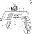
- Fig. 5 can be seen particularly well, as in the preferred embodiment that is shown here, the exact course of the support arm 15 is provided. It is shown that the first leg 21 is essentially straight. Measured on the center line of the first leg 21, from the geometric pivot axis of the Pivot bearing 14 from up to the beginning of the arc-shaped apex 22, it has a length of, for example, about 160 mm.
- the support arm In the area of the apex 22, the support arm here has a minimum arc radius of approximately 70 mm.
- a particularly important parameter for the tool changing device is the radius of the horizontal swivel circle 20. This is measured between the geometric vertical swivel axis 17 of the swivel bearing 14 and the center of the tool holder 19 of the double gripper 18, as in FIG Fig. 3 and 5 evident.
- the radius of the pivot circle 20 measured in this way has a size of approximately 285 mm in the illustrated and preferred exemplary embodiment. With a more compact tool changing device you can work with a smaller radius down to about 220 mm, with a larger tool changing device, however, a radius of up to 380 mm or a little more can also result.
- the other dimensions follow the specification by the radius of the pivoting circle 20 in a corresponding manner.
- the intermediate wall 24 has a passage opening 25. This passage opening 25 is used to transport a tool 11 from the tool magazine 9 to the spindle 8 of the traveling column 7 and vice versa by means of the tool changing device 12. By means of the tool changing device 12, such a tool 11 is, as it were, passed through the passage opening 25 in the intermediate wall 24.
- the tool magazine 9 is, as already evident from Fig. 1 results, arranged on the side of the partition wall 24 facing away from the workpiece positioning area 4.
- the pivot bearing 14 of the support arm 15 of the tool changing device 12 is arranged near the partition 24 on the side facing away from the workpiece positioning area 4, namely next to the edge of the passage opening 25.
- the pivot bearing 14 can possibly be fixedly attached to the partition 24. In the illustrated and preferred exemplary embodiment, however, the pivot bearing 14 is attached to the cross member 13, which in turn is attached to the tool magazine 9.
- a machining center is created which, with processes that are just as useful as in the prior art according to EP 2 881 219 A1 in the area of the transfer of the tools to the spindle 8 of the traveling column 7 is even more compact than previously known.
- the passage opening 25 in the intermediate wall 24 can be made much narrower than before. The better the workpiece positioning area 4 is shielded when the machining center is in operation.
Landscapes
- Engineering & Computer Science (AREA)
- Mechanical Engineering (AREA)
- Automatic Tool Replacement In Machine Tools (AREA)
Claims (12)
- Dispositif de changement d'outils à utiliser en liaison avec une colonne mobile (7) d'un centre d'usinage pour l'usinage d'une pièce au moyen de différents outils (11),
avec un bras de support (15), qui est monté à une extrémité au moyen d'un palier pivotant (14), qui peut être monté dans le centre d'usinage,
dans lequel le bras de support (15) comporte une double pince (18) avec deux porte-outils (19) à l'autre extrémité et peut pivoter autour d'un axe de pivotement vertical (17) au moyen du palier pivotant (14) de sorte que les porte-outils (19) se déplacent sur un cercle de pivotement horizontal (20),
dans lequel les deux porte-outils (19) de la double pince (18) sont disposés de manière décalée dans la direction circonférentielle du cercle de pivotement (20) et sont orientés radialement vers l'extérieur, ouverts par rapport au cercle de pivotement (20),
caractérisé,
en ce que le bras de support (15) entre le palier pivotant (14) et la double pince (18) est conçu en vue de dessus comme un arc en forme de U dans la direction Z, avec une première branche (21) qui part du palier de pivotement (14) et se transformeen une deuxième branche (23) s'étendant en arc jusqu'à la double pince (18), en formant un sommet (22) en forme d'arc. - Dispositif de changement d'outils selon la revendication 1, caractérisé en ce que
le bras de support (15) est de forme asymétrique, la première branche (21) ayant une longueur sensiblement inférieure à celle de la seconde branche (23). - Dispositif de changement d'outils selon la revendication 1 ou 2, caractérisé en ce que
la première branche (21) s'étend de façon sensiblement rectiligne et, mesurée sur l'axe central de la première branche (21) à partir de l'axe géométrique de pivotement (17) du palier de pivotement (14) jusqu'au début de l'apex en forme d'arc (22), a une longueur de 120 mm à 240 mm, de préférence de 150 mm à 180 mm. - Dispositif de changement d'outils selon l'une quelconque des revendications 1 à 3, caractérisé en ce que
la deuxième branche (23), mesurée de la ligne centrale au point de rotation du sommet (22), a une longueur de 200 mm à 600 mm, de préférence de 320 mm à 400 mm. - Dispositif de changement d'outils selon l'une quelconque des revendications 1 à 4, caractérisé en ce que
la deuxième branche (23) a un rayon d'arc qui diminue du sommet (22) vers la double pince (18). - Dispositif de changement d'outils selon l'une quelconque des revendications 1 à 5, caractérisé en ce que
le cercle de pivotement (20), mesuré entre l'axe géométrique de pivotement (17) du palier pivotant (14) et le centre du porte-outil (19) de la pince double (18), a un rayon de 200 mm à 400 mm, de préférence de 220 mm à 380 mm, plus préférablement de 260 mm à 300 mm. - Dispositif de changement d'outils selon l'une quelconque des revendications 1 à 6, caractérisé par que
l'apex (22) a un rayon d'arc minimum de 50 mm à 100 mm, de préférence de 60 mm à 80 mm. - Centre d'usinage pour l'usinage d'une pièce au moyen de différents outils (11), avec un support de base de la machine (1), dont l'orientation longitudinale horizontale définit un axe X (direction X), dont l'orientation transversale horizontale définit un axe Y (direction Y) et dont l'orientation verticale définit un axe Z (direction Z), et
sur le support de base de la machine (1), une zone de positionnement de la pièce (4) s'étendant dans la direction X et un guide de déplacement (6) s'étendant parallèlement à la zone de positionnement de la pièce (4),
dans lequel une colonne mobile (7) avec une broche mobile porte-outil (8) peut être déplacée d'avant en arrière sur le guide de déplacement (6) parallèlement à la zone de positionnement de la pièce (4), et
dans lequel le centre d'usinage comprend en outre un magasin d'outils (9) ayant une pluralité de porte-outils (10) pour différents outils individuels (11),
caractérisé en ce que,
le centre d'usinage comporte un dispositif de changement d'outil (12) selon l'une des revendications 1 à 7, avec lequel un outil (11) peut être transporté dans chaque cas du magasin d'outils (9) à la broche mobile (8) montée sur la colonne mobile (7) et retour. - Centre d'usinage selon la revendication 8, caractérisé en ce que
une paroi intermédiaire (24) destinée à délimiter la zone de positionnement de la pièce (4) est disposée sur le support de base de la machine (1), à côté de la zone de positionnement de la pièce (4),
en ce que la paroi intermédiaire (24) comporte une ouverture traversante (25),
en ce que le magasin d'outils (9) est disposé sur le côté de la paroi intermédiare (24) opposé à la zone de positionnement de la pièce (4),
en ce que le palier pivotant (14) du bras de support (15) du dispositif de changement d'outil (12) est disposé à proximité de la paroi intermédiaire (24) sur le côté opposé à la zone de positionnement de la pièce (4), à côté du bord de l'ouverture traversante (25), et
en ce que le bras de support (15) est orienté de telle sorte que la double pince (18) peut être pivotée à travers l'ouverture traversante (25) dans la zone de positionnement de la pièce (4) vers la broche (8) de la colonne mobile (7). - Centre d'usinage selon la revendication 9, caractérisé en ce que,
même lorsque le bras de support (15) est pivoté le plus loin possible vers la broche (8), la première branche (21), le sommet (22) et une partie de la deuxième branche (23) du bras de support (15) restent sur le côté de la paroi intermédiaire (24) tourné vers le palier pivotant (14). - Centre d'usinage selon la revendication 9 ou 10, caractérisé en ce que l'ouverture traversante (25) dans la paroi intermédiaire (24) peut être fermée au moyen d'une fermeture mobile (28), de préférence sous la forme d'une paroi pliante.
- Centre d'usinage selon l'une des revendications 9 à 11, caractérisé en ce que la distance du bord de l'ouverture traversante (25) et/ou, en présence d'une fermeture mobile (28), du bord de la fermeture ouverte (28) par rapport à l'axe géométrique de pivotement (17) du palier pivotant (14) est comprise entre 95% et 80% de la longueur de la première branche (21), mesurée sur l'axe central de la première branche (21) depuis l'axe géométrique de pivotement (17) du palier pivotant (14) jusqu'au début du sommet (22) en forme d'arc.
Applications Claiming Priority (1)
| Application Number | Priority Date | Filing Date | Title |
|---|---|---|---|
| DE202016005107.6U DE202016005107U1 (de) | 2016-08-24 | 2016-08-24 | Werkzeugwechselvorrichtung und Bearbeitungszentrum mit einer Werkzeugwechselvorrichtung |
Publications (2)
| Publication Number | Publication Date |
|---|---|
| EP3287231A1 EP3287231A1 (fr) | 2018-02-28 |
| EP3287231B1 true EP3287231B1 (fr) | 2020-11-04 |
Family
ID=59522906
Family Applications (1)
| Application Number | Title | Priority Date | Filing Date |
|---|---|---|---|
| EP17020331.9A Active EP3287231B1 (fr) | 2016-08-24 | 2017-08-03 | Dispositif de changement d'outil et centre d'usinage doté d'un dispositif de changement d'outil |
Country Status (2)
| Country | Link |
|---|---|
| EP (1) | EP3287231B1 (fr) |
| DE (1) | DE202016005107U1 (fr) |
Families Citing this family (2)
| Publication number | Priority date | Publication date | Assignee | Title |
|---|---|---|---|---|
| DE102021125634A1 (de) | 2021-10-04 | 2023-04-06 | Homag Bohrsysteme Gmbh | Werkzeugmaschine sowie Verfahren |
| CN118003132B (zh) * | 2024-04-09 | 2024-06-11 | 江西台正智能科技有限公司 | 自动换刀模块及应用该模块的精雕机 |
Family Cites Families (4)
| Publication number | Priority date | Publication date | Assignee | Title |
|---|---|---|---|---|
| DE3636498A1 (de) * | 1986-10-27 | 1988-05-05 | Maho Werkzeugmaschbau Babel | Werkzeugwechsler fuer programmgesteuerte universal-fraes- und bohrmaschinen |
| DE202006015098U1 (de) * | 2006-10-02 | 2006-11-23 | Deckel Maho Pfronten Gmbh | Werkzeugmaschine mit Rundkabine |
| DE202009002504U1 (de) | 2009-02-06 | 2010-06-24 | Hedelius Maschinenfabrik Gmbh | Bearbeitungszentrum |
| DE202013009776U1 (de) | 2013-12-03 | 2015-03-05 | Hedelius Maschinenfabrik Gmbh | Werkzeugwechselvorrichtung zur Verwendung in einem Bearbeitungszentrum und Bearbeitungszentrum zur maschinellen Bearbeitung eines Werkstücks |
-
2016
- 2016-08-24 DE DE202016005107.6U patent/DE202016005107U1/de not_active Expired - Lifetime
-
2017
- 2017-08-03 EP EP17020331.9A patent/EP3287231B1/fr active Active
Non-Patent Citations (1)
| Title |
|---|
| None * |
Also Published As
| Publication number | Publication date |
|---|---|
| EP3287231A1 (fr) | 2018-02-28 |
| DE202016005107U1 (de) | 2017-11-27 |
Similar Documents
| Publication | Publication Date | Title |
|---|---|---|
| DE102007051904B3 (de) | Werkzeugmaschine | |
| DE102017110035A1 (de) | Werkzeugmaschine | |
| DE102017110029A1 (de) | Werkzeugmaschine | |
| DE3533089C1 (de) | Werkzeugmaschine mit Spritzschutzelement | |
| DE102014113652B4 (de) | Werkzeugwechsler mit Abdeckungen | |
| DE3544193A1 (de) | Automatische werkzeugmaschine mit einer drehschalteinrichtung | |
| DE3317554C2 (fr) | ||
| EP3287231B1 (fr) | Dispositif de changement d'outil et centre d'usinage doté d'un dispositif de changement d'outil | |
| DE19938442A1 (de) | Automatische Werkzeugwechselvorrichtung für Werkzeugmaschinen | |
| EP0154349A2 (fr) | Dispositif pour changer des outils ou des objets similaires dans la broche d'une machine-outil | |
| DE10310997A1 (de) | Mehrspindeldrehmaschine | |
| EP2881219A1 (fr) | Dispositif de changement d'outil destiné à être utilisé dans un centre d'usinage et centre d'usinage destiné à l'usinage mécanique d'une pièce à usiner | |
| EP3115164B1 (fr) | Machine d'usinage | |
| DE19725043B4 (de) | Vorrichtung zum Bearbeiten von stangenförmigen Werkstücken | |
| EP3334559B1 (fr) | Machine-outil | |
| EP3511099A1 (fr) | Scie à ruban | |
| DE102008025385B4 (de) | Palettenaustauscher | |
| DE202007013125U1 (de) | Einrichtung zur Bearbeitung insbesondere großer Durchmesser eines Werkstücks | |
| AT518740B1 (de) | Bearbeitungszentrum | |
| WO2009033929A2 (fr) | Tour | |
| DE4022706C2 (de) | Drehmaschine | |
| EP3684533B1 (fr) | Tournage de pièces à usiner sur une machine-outil | |
| DE602004007135T2 (de) | Vorrichtung zur Bearbeitung mit Gegenspindel in einer Mehrspindeldrehmaschine | |
| WO2012028212A1 (fr) | Machine-outil à broche principale pivotante | |
| DE10358381A1 (de) | Bearbeitungszentrum mit insbesondere vertikal angeordneten Bearbeitungsspindeln |
Legal Events
| Date | Code | Title | Description |
|---|---|---|---|
| PUAI | Public reference made under article 153(3) epc to a published international application that has entered the european phase |
Free format text: ORIGINAL CODE: 0009012 |
|
| STAA | Information on the status of an ep patent application or granted ep patent |
Free format text: STATUS: THE APPLICATION HAS BEEN PUBLISHED |
|
| AK | Designated contracting states |
Kind code of ref document: A1 Designated state(s): AL AT BE BG CH CY CZ DE DK EE ES FI FR GB GR HR HU IE IS IT LI LT LU LV MC MK MT NL NO PL PT RO RS SE SI SK SM TR |
|
| AX | Request for extension of the european patent |
Extension state: BA ME |
|
| STAA | Information on the status of an ep patent application or granted ep patent |
Free format text: STATUS: REQUEST FOR EXAMINATION WAS MADE |
|
| 17P | Request for examination filed |
Effective date: 20180723 |
|
| RBV | Designated contracting states (corrected) |
Designated state(s): AL AT BE BG CH CY CZ DE DK EE ES FI FR GB GR HR HU IE IS IT LI LT LU LV MC MK MT NL NO PL PT RO RS SE SI SK SM TR |
|
| GRAP | Despatch of communication of intention to grant a patent |
Free format text: ORIGINAL CODE: EPIDOSNIGR1 |
|
| STAA | Information on the status of an ep patent application or granted ep patent |
Free format text: STATUS: GRANT OF PATENT IS INTENDED |
|
| RIC1 | Information provided on ipc code assigned before grant |
Ipc: B23Q 3/157 20060101AFI20200622BHEP Ipc: B23Q 3/155 20060101ALN20200622BHEP |
|
| INTG | Intention to grant announced |
Effective date: 20200716 |
|
| GRAS | Grant fee paid |
Free format text: ORIGINAL CODE: EPIDOSNIGR3 |
|
| GRAA | (expected) grant |
Free format text: ORIGINAL CODE: 0009210 |
|
| STAA | Information on the status of an ep patent application or granted ep patent |
Free format text: STATUS: THE PATENT HAS BEEN GRANTED |
|
| AK | Designated contracting states |
Kind code of ref document: B1 Designated state(s): AL AT BE BG CH CY CZ DE DK EE ES FI FR GB GR HR HU IE IS IT LI LT LU LV MC MK MT NL NO PL PT RO RS SE SI SK SM TR |
|
| REG | Reference to a national code |
Ref country code: GB Ref legal event code: FG4D Free format text: NOT ENGLISH |
|
| REG | Reference to a national code |
Ref country code: CH Ref legal event code: EP |
|
| REG | Reference to a national code |
Ref country code: AT Ref legal event code: REF Ref document number: 1330179 Country of ref document: AT Kind code of ref document: T Effective date: 20201115 |
|
| REG | Reference to a national code |
Ref country code: DE Ref legal event code: R096 Ref document number: 502017007981 Country of ref document: DE |
|
| REG | Reference to a national code |
Ref country code: IE Ref legal event code: FG4D Free format text: LANGUAGE OF EP DOCUMENT: GERMAN |
|
| REG | Reference to a national code |
Ref country code: NL Ref legal event code: MP Effective date: 20201104 |
|
| PG25 | Lapsed in a contracting state [announced via postgrant information from national office to epo] |
Ref country code: GR Free format text: LAPSE BECAUSE OF FAILURE TO SUBMIT A TRANSLATION OF THE DESCRIPTION OR TO PAY THE FEE WITHIN THE PRESCRIBED TIME-LIMIT Effective date: 20210205 Ref country code: FI Free format text: LAPSE BECAUSE OF FAILURE TO SUBMIT A TRANSLATION OF THE DESCRIPTION OR TO PAY THE FEE WITHIN THE PRESCRIBED TIME-LIMIT Effective date: 20201104 Ref country code: RS Free format text: LAPSE BECAUSE OF FAILURE TO SUBMIT A TRANSLATION OF THE DESCRIPTION OR TO PAY THE FEE WITHIN THE PRESCRIBED TIME-LIMIT Effective date: 20201104 Ref country code: PT Free format text: LAPSE BECAUSE OF FAILURE TO SUBMIT A TRANSLATION OF THE DESCRIPTION OR TO PAY THE FEE WITHIN THE PRESCRIBED TIME-LIMIT Effective date: 20210304 Ref country code: NO Free format text: LAPSE BECAUSE OF FAILURE TO SUBMIT A TRANSLATION OF THE DESCRIPTION OR TO PAY THE FEE WITHIN THE PRESCRIBED TIME-LIMIT Effective date: 20210204 |
|
| PG25 | Lapsed in a contracting state [announced via postgrant information from national office to epo] |
Ref country code: SE Free format text: LAPSE BECAUSE OF FAILURE TO SUBMIT A TRANSLATION OF THE DESCRIPTION OR TO PAY THE FEE WITHIN THE PRESCRIBED TIME-LIMIT Effective date: 20201104 Ref country code: LV Free format text: LAPSE BECAUSE OF FAILURE TO SUBMIT A TRANSLATION OF THE DESCRIPTION OR TO PAY THE FEE WITHIN THE PRESCRIBED TIME-LIMIT Effective date: 20201104 Ref country code: IS Free format text: LAPSE BECAUSE OF FAILURE TO SUBMIT A TRANSLATION OF THE DESCRIPTION OR TO PAY THE FEE WITHIN THE PRESCRIBED TIME-LIMIT Effective date: 20210304 Ref country code: PL Free format text: LAPSE BECAUSE OF FAILURE TO SUBMIT A TRANSLATION OF THE DESCRIPTION OR TO PAY THE FEE WITHIN THE PRESCRIBED TIME-LIMIT Effective date: 20201104 Ref country code: BG Free format text: LAPSE BECAUSE OF FAILURE TO SUBMIT A TRANSLATION OF THE DESCRIPTION OR TO PAY THE FEE WITHIN THE PRESCRIBED TIME-LIMIT Effective date: 20210204 Ref country code: ES Free format text: LAPSE BECAUSE OF FAILURE TO SUBMIT A TRANSLATION OF THE DESCRIPTION OR TO PAY THE FEE WITHIN THE PRESCRIBED TIME-LIMIT Effective date: 20201104 |
|
| REG | Reference to a national code |
Ref country code: LT Ref legal event code: MG9D |
|
| PG25 | Lapsed in a contracting state [announced via postgrant information from national office to epo] |
Ref country code: HR Free format text: LAPSE BECAUSE OF FAILURE TO SUBMIT A TRANSLATION OF THE DESCRIPTION OR TO PAY THE FEE WITHIN THE PRESCRIBED TIME-LIMIT Effective date: 20201104 |
|
| PG25 | Lapsed in a contracting state [announced via postgrant information from national office to epo] |
Ref country code: RO Free format text: LAPSE BECAUSE OF FAILURE TO SUBMIT A TRANSLATION OF THE DESCRIPTION OR TO PAY THE FEE WITHIN THE PRESCRIBED TIME-LIMIT Effective date: 20201104 Ref country code: SK Free format text: LAPSE BECAUSE OF FAILURE TO SUBMIT A TRANSLATION OF THE DESCRIPTION OR TO PAY THE FEE WITHIN THE PRESCRIBED TIME-LIMIT Effective date: 20201104 Ref country code: EE Free format text: LAPSE BECAUSE OF FAILURE TO SUBMIT A TRANSLATION OF THE DESCRIPTION OR TO PAY THE FEE WITHIN THE PRESCRIBED TIME-LIMIT Effective date: 20201104 Ref country code: CZ Free format text: LAPSE BECAUSE OF FAILURE TO SUBMIT A TRANSLATION OF THE DESCRIPTION OR TO PAY THE FEE WITHIN THE PRESCRIBED TIME-LIMIT Effective date: 20201104 Ref country code: SM Free format text: LAPSE BECAUSE OF FAILURE TO SUBMIT A TRANSLATION OF THE DESCRIPTION OR TO PAY THE FEE WITHIN THE PRESCRIBED TIME-LIMIT Effective date: 20201104 Ref country code: LT Free format text: LAPSE BECAUSE OF FAILURE TO SUBMIT A TRANSLATION OF THE DESCRIPTION OR TO PAY THE FEE WITHIN THE PRESCRIBED TIME-LIMIT Effective date: 20201104 |
|
| REG | Reference to a national code |
Ref country code: DE Ref legal event code: R097 Ref document number: 502017007981 Country of ref document: DE |
|
| PG25 | Lapsed in a contracting state [announced via postgrant information from national office to epo] |
Ref country code: DK Free format text: LAPSE BECAUSE OF FAILURE TO SUBMIT A TRANSLATION OF THE DESCRIPTION OR TO PAY THE FEE WITHIN THE PRESCRIBED TIME-LIMIT Effective date: 20201104 |
|
| PLBE | No opposition filed within time limit |
Free format text: ORIGINAL CODE: 0009261 |
|
| STAA | Information on the status of an ep patent application or granted ep patent |
Free format text: STATUS: NO OPPOSITION FILED WITHIN TIME LIMIT |
|
| 26N | No opposition filed |
Effective date: 20210805 |
|
| PG25 | Lapsed in a contracting state [announced via postgrant information from national office to epo] |
Ref country code: AL Free format text: LAPSE BECAUSE OF FAILURE TO SUBMIT A TRANSLATION OF THE DESCRIPTION OR TO PAY THE FEE WITHIN THE PRESCRIBED TIME-LIMIT Effective date: 20201104 Ref country code: NL Free format text: LAPSE BECAUSE OF FAILURE TO SUBMIT A TRANSLATION OF THE DESCRIPTION OR TO PAY THE FEE WITHIN THE PRESCRIBED TIME-LIMIT Effective date: 20201104 |
|
| PG25 | Lapsed in a contracting state [announced via postgrant information from national office to epo] |
Ref country code: SI Free format text: LAPSE BECAUSE OF FAILURE TO SUBMIT A TRANSLATION OF THE DESCRIPTION OR TO PAY THE FEE WITHIN THE PRESCRIBED TIME-LIMIT Effective date: 20201104 |
|
| PG25 | Lapsed in a contracting state [announced via postgrant information from national office to epo] |
Ref country code: MC Free format text: LAPSE BECAUSE OF FAILURE TO SUBMIT A TRANSLATION OF THE DESCRIPTION OR TO PAY THE FEE WITHIN THE PRESCRIBED TIME-LIMIT Effective date: 20201104 |
|
| REG | Reference to a national code |
Ref country code: BE Ref legal event code: MM Effective date: 20210831 |
|
| PG25 | Lapsed in a contracting state [announced via postgrant information from national office to epo] |
Ref country code: IS Free format text: LAPSE BECAUSE OF FAILURE TO SUBMIT A TRANSLATION OF THE DESCRIPTION OR TO PAY THE FEE WITHIN THE PRESCRIBED TIME-LIMIT Effective date: 20210304 Ref country code: LU Free format text: LAPSE BECAUSE OF NON-PAYMENT OF DUE FEES Effective date: 20210803 |
|
| PG25 | Lapsed in a contracting state [announced via postgrant information from national office to epo] |
Ref country code: IE Free format text: LAPSE BECAUSE OF NON-PAYMENT OF DUE FEES Effective date: 20210803 Ref country code: BE Free format text: LAPSE BECAUSE OF NON-PAYMENT OF DUE FEES Effective date: 20210831 |
|
| PG25 | Lapsed in a contracting state [announced via postgrant information from national office to epo] |
Ref country code: HU Free format text: LAPSE BECAUSE OF FAILURE TO SUBMIT A TRANSLATION OF THE DESCRIPTION OR TO PAY THE FEE WITHIN THE PRESCRIBED TIME-LIMIT; INVALID AB INITIO Effective date: 20170803 |
|
| PG25 | Lapsed in a contracting state [announced via postgrant information from national office to epo] |
Ref country code: CY Free format text: LAPSE BECAUSE OF FAILURE TO SUBMIT A TRANSLATION OF THE DESCRIPTION OR TO PAY THE FEE WITHIN THE PRESCRIBED TIME-LIMIT Effective date: 20201104 |
|
| PG25 | Lapsed in a contracting state [announced via postgrant information from national office to epo] |
Ref country code: MK Free format text: LAPSE BECAUSE OF FAILURE TO SUBMIT A TRANSLATION OF THE DESCRIPTION OR TO PAY THE FEE WITHIN THE PRESCRIBED TIME-LIMIT Effective date: 20201104 |
|
| PG25 | Lapsed in a contracting state [announced via postgrant information from national office to epo] |
Ref country code: MT Free format text: LAPSE BECAUSE OF FAILURE TO SUBMIT A TRANSLATION OF THE DESCRIPTION OR TO PAY THE FEE WITHIN THE PRESCRIBED TIME-LIMIT Effective date: 20201104 |
|
| PGFP | Annual fee paid to national office [announced via postgrant information from national office to epo] |
Ref country code: DE Payment date: 20250819 Year of fee payment: 9 |
|
| PGFP | Annual fee paid to national office [announced via postgrant information from national office to epo] |
Ref country code: IT Payment date: 20250825 Year of fee payment: 9 |
|
| PGFP | Annual fee paid to national office [announced via postgrant information from national office to epo] |
Ref country code: GB Payment date: 20250821 Year of fee payment: 9 |
|
| PGFP | Annual fee paid to national office [announced via postgrant information from national office to epo] |
Ref country code: FR Payment date: 20250828 Year of fee payment: 9 Ref country code: AT Payment date: 20250821 Year of fee payment: 9 |
|
| PGFP | Annual fee paid to national office [announced via postgrant information from national office to epo] |
Ref country code: CH Payment date: 20250901 Year of fee payment: 9 |
|
| PG25 | Lapsed in a contracting state [announced via postgrant information from national office to epo] |
Ref country code: TR Free format text: LAPSE BECAUSE OF FAILURE TO SUBMIT A TRANSLATION OF THE DESCRIPTION OR TO PAY THE FEE WITHIN THE PRESCRIBED TIME-LIMIT Effective date: 20201104 |