EP3287625A1 - Steuerungssystem und -verfahren zur vermeidung von verdichterpumpem eines gasturbinenmotors - Google Patents
Steuerungssystem und -verfahren zur vermeidung von verdichterpumpem eines gasturbinenmotors Download PDFInfo
- Publication number
- EP3287625A1 EP3287625A1 EP17184600.9A EP17184600A EP3287625A1 EP 3287625 A1 EP3287625 A1 EP 3287625A1 EP 17184600 A EP17184600 A EP 17184600A EP 3287625 A1 EP3287625 A1 EP 3287625A1
- Authority
- EP
- European Patent Office
- Prior art keywords
- surge
- fuel
- engine
- gas turbine
- processor
- Prior art date
- Legal status (The legal status is an assumption and is not a legal conclusion. Google has not performed a legal analysis and makes no representation as to the accuracy of the status listed.)
- Granted
Links
Images

Classifications
-
- F—MECHANICAL ENGINEERING; LIGHTING; HEATING; WEAPONS; BLASTING
- F04—POSITIVE - DISPLACEMENT MACHINES FOR LIQUIDS; PUMPS FOR LIQUIDS OR ELASTIC FLUIDS
- F04D—NON-POSITIVE-DISPLACEMENT PUMPS
- F04D27/00—Control, e.g. regulation, of pumps, pumping installations or pumping systems specially adapted for elastic fluids
- F04D27/02—Surge control
- F04D27/0246—Surge control by varying geometry within the pumps, e.g. by adjusting vanes
-
- F—MECHANICAL ENGINEERING; LIGHTING; HEATING; WEAPONS; BLASTING
- F02—COMBUSTION ENGINES; HOT-GAS OR COMBUSTION-PRODUCT ENGINE PLANTS
- F02C—GAS-TURBINE PLANTS; AIR INTAKES FOR JET-PROPULSION PLANTS; CONTROLLING FUEL SUPPLY IN AIR-BREATHING JET-PROPULSION PLANTS
- F02C9/00—Controlling gas-turbine plants; Controlling fuel supply in air- breathing jet-propulsion plants
- F02C9/48—Control of fuel supply conjointly with another control of the plant
- F02C9/50—Control of fuel supply conjointly with another control of the plant with control of working fluid flow
- F02C9/52—Control of fuel supply conjointly with another control of the plant with control of working fluid flow by bleeding or by-passing the working fluid
-
- F—MECHANICAL ENGINEERING; LIGHTING; HEATING; WEAPONS; BLASTING
- F02—COMBUSTION ENGINES; HOT-GAS OR COMBUSTION-PRODUCT ENGINE PLANTS
- F02C—GAS-TURBINE PLANTS; AIR INTAKES FOR JET-PROPULSION PLANTS; CONTROLLING FUEL SUPPLY IN AIR-BREATHING JET-PROPULSION PLANTS
- F02C9/00—Controlling gas-turbine plants; Controlling fuel supply in air- breathing jet-propulsion plants
- F02C9/48—Control of fuel supply conjointly with another control of the plant
- F02C9/50—Control of fuel supply conjointly with another control of the plant with control of working fluid flow
- F02C9/54—Control of fuel supply conjointly with another control of the plant with control of working fluid flow by throttling the working fluid, by adjusting vanes
-
- F—MECHANICAL ENGINEERING; LIGHTING; HEATING; WEAPONS; BLASTING
- F04—POSITIVE - DISPLACEMENT MACHINES FOR LIQUIDS; PUMPS FOR LIQUIDS OR ELASTIC FLUIDS
- F04D—NON-POSITIVE-DISPLACEMENT PUMPS
- F04D27/00—Control, e.g. regulation, of pumps, pumping installations or pumping systems specially adapted for elastic fluids
- F04D27/001—Testing thereof; Determination or simulation of flow characteristics; Stall or surge detection, e.g. condition monitoring
-
- F—MECHANICAL ENGINEERING; LIGHTING; HEATING; WEAPONS; BLASTING
- F04—POSITIVE - DISPLACEMENT MACHINES FOR LIQUIDS; PUMPS FOR LIQUIDS OR ELASTIC FLUIDS
- F04D—NON-POSITIVE-DISPLACEMENT PUMPS
- F04D29/00—Details, component parts, or accessories
- F04D29/40—Casings; Connections of working fluid
- F04D29/52—Casings; Connections of working fluid for axial pumps
- F04D29/54—Fluid-guiding means, e.g. diffusers
- F04D29/56—Fluid-guiding means, e.g. diffusers adjustable
- F04D29/563—Fluid-guiding means, e.g. diffusers adjustable specially adapted for elastic fluid pumps
-
- F—MECHANICAL ENGINEERING; LIGHTING; HEATING; WEAPONS; BLASTING
- F05—INDEXING SCHEMES RELATING TO ENGINES OR PUMPS IN VARIOUS SUBCLASSES OF CLASSES F01-F04
- F05D—INDEXING SCHEME FOR ASPECTS RELATING TO NON-POSITIVE-DISPLACEMENT MACHINES OR ENGINES, GAS-TURBINES OR JET-PROPULSION PLANTS
- F05D2220/00—Application
- F05D2220/50—Application for auxiliary power units (APU's)
-
- F—MECHANICAL ENGINEERING; LIGHTING; HEATING; WEAPONS; BLASTING
- F05—INDEXING SCHEMES RELATING TO ENGINES OR PUMPS IN VARIOUS SUBCLASSES OF CLASSES F01-F04
- F05D—INDEXING SCHEME FOR ASPECTS RELATING TO NON-POSITIVE-DISPLACEMENT MACHINES OR ENGINES, GAS-TURBINES OR JET-PROPULSION PLANTS
- F05D2270/00—Control
- F05D2270/01—Purpose of the control system
- F05D2270/10—Purpose of the control system to cope with, or avoid, compressor flow instabilities
- F05D2270/101—Compressor surge or stall
-
- F—MECHANICAL ENGINEERING; LIGHTING; HEATING; WEAPONS; BLASTING
- F05—INDEXING SCHEMES RELATING TO ENGINES OR PUMPS IN VARIOUS SUBCLASSES OF CLASSES F01-F04
- F05D—INDEXING SCHEME FOR ASPECTS RELATING TO NON-POSITIVE-DISPLACEMENT MACHINES OR ENGINES, GAS-TURBINES OR JET-PROPULSION PLANTS
- F05D2270/00—Control
- F05D2270/30—Control parameters, e.g. input parameters
- F05D2270/301—Pressure
- F05D2270/3011—Inlet pressure
-
- F—MECHANICAL ENGINEERING; LIGHTING; HEATING; WEAPONS; BLASTING
- F05—INDEXING SCHEMES RELATING TO ENGINES OR PUMPS IN VARIOUS SUBCLASSES OF CLASSES F01-F04
- F05D—INDEXING SCHEME FOR ASPECTS RELATING TO NON-POSITIVE-DISPLACEMENT MACHINES OR ENGINES, GAS-TURBINES OR JET-PROPULSION PLANTS
- F05D2270/00—Control
- F05D2270/30—Control parameters, e.g. input parameters
- F05D2270/303—Temperature
-
- F—MECHANICAL ENGINEERING; LIGHTING; HEATING; WEAPONS; BLASTING
- F05—INDEXING SCHEMES RELATING TO ENGINES OR PUMPS IN VARIOUS SUBCLASSES OF CLASSES F01-F04
- F05D—INDEXING SCHEME FOR ASPECTS RELATING TO NON-POSITIVE-DISPLACEMENT MACHINES OR ENGINES, GAS-TURBINES OR JET-PROPULSION PLANTS
- F05D2270/00—Control
- F05D2270/30—Control parameters, e.g. input parameters
- F05D2270/312—Air pressure
-
- F—MECHANICAL ENGINEERING; LIGHTING; HEATING; WEAPONS; BLASTING
- F05—INDEXING SCHEMES RELATING TO ENGINES OR PUMPS IN VARIOUS SUBCLASSES OF CLASSES F01-F04
- F05D—INDEXING SCHEME FOR ASPECTS RELATING TO NON-POSITIVE-DISPLACEMENT MACHINES OR ENGINES, GAS-TURBINES OR JET-PROPULSION PLANTS
- F05D2270/00—Control
- F05D2270/30—Control parameters, e.g. input parameters
- F05D2270/313—Air temperature
Definitions
- the present invention generally relates to gas turbine engines, and more particularly relates to systems and methods for avoiding compressor surge in gas turbine engines.
- a gas turbine engine may be used to supply power to various types of vehicles and systems.
- gas turbine engines may be used to supply propulsion power to an aircraft.
- Some gas turbine engines may also serve as auxiliary power units (APUs) to supplement main propulsion engines in providing electrical and/or pneumatic power, and/or to start the propulsion engines.
- APUs auxiliary power units
- gas turbine engines are designed so that the compressor operates with sufficient surge margin. If the surge margin is inadequate, a compressor surge can occur resulting, for example, in a stall or a compressor surge, in which an undesirable reversal of flow occurs.
- Most gas turbine engines control the positions of variable inlet and/or exit geometries or bleed valves to avoid compressor surge. Unfortunately, most gas turbine engines do not include systems to detect an impending surge or even if a compressor surge has occurred. Moreover, gas turbine engines do not include systems that can modify the areas of operation to be avoided in the event that the surge margin is reduced.
- a compressor surge avoidance control method for a gas turbine engine includes sensing a plurality of engine inlet parameters, and receiving, in a processor, a fuel command value.
- the sensed parameters are processed in the processor to determine a surge fuel value that is representative of a fuel flow above which, for the sensed engine inlet parameters, a compressor surge will likely occur.
- the surge fuel value and the fuel command value are compared, in the processor, and a protective action signal is generated if the fuel command value exceeds the surge fuel value.
- a compressor surge avoidance control system for a gas turbine engine includes a plurality of engine inlet sensors and a processor. Each sensor is configured to sense an engine inlet parameter and supply an engine inlet parameter signal representative of the sensed engine inlet parameter.
- the processor is coupled to receive the engine inlet parameter signals and a fuel command value.
- the processor is configured, upon receipt of the engine inlet parameter signals and the fuel command, to: (i) determine a surge fuel value, the surge fuel value representative of a fuel flow above which, for the sensed engine inlet parameters, a compressor surge will likely occur, (ii) compare the surge fuel value and the fuel command, and (iii) generate a protective action signal if the fuel command value exceeds the surge fuel value.
- a compressor surge avoidance control system for a gas turbine engine includes an engine inlet air temperature sensor, an engine inlet air pressure sensor, and a processor.
- the engine inlet air temperature sensor is configured to sense engine inlet air temperature and supply an engine inlet air temperature signal representative thereof.
- the engine inlet air pressure sensor is configured to sense engine inlet air pressure and supply an engine inlet air pressure signal representative thereof.
- the processor is coupled to receive the engine inlet air temperature signal, the engine inlet air pressure signal, and a fuel command value, and is configured to: (i) determine a surge fuel value, the surge fuel value representative of a fuel flow above which, for the sensed engine inlet parameters, a compressor surge will likely occur, (ii) compare the surge fuel value and the fuel command, and (iii) generate one or both of an operator alert signal and a load adjustment signal that causes a load reduction on the gas turbine engine.
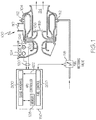
- FIG. 1 a simplified cross section view of an exemplary embodiment of an auxiliary power unit (APU) is shown.
- the APU 100 includes a compressor 102, a combustor 104, and a turbine 106. Air is directed into the compressor 102 via an air inlet 108.
- the compressor 102 raises the pressure of the air and supplies compressed air to both the combustor 104 and, in the depicted embodiment, to a bleed air outlet port 110.
- the compressed air is mixed with fuel that is supplied to the combustor 104 from a non-illustrated fuel source via a plurality of fuel nozzles 112.
- the fuel/air mixture is combusted, generating high-energy gas, which is then directed into the turbine 106.
- the high-energy gas expands through the turbine 106, where it gives up much of its energy and causes the turbine 106 to rotate.
- the gas is then exhausted from the APU 100 via an exhaust gas outlet 114.
- the turbine 106 drives, via a turbine shaft 116, various types of equipment that may be mounted in, or coupled to, the APU 100.
- the turbine 106 drives the compressor 102.
- the turbine 106 may also be used to drive a generator and/or a load compressor and/or other rotational equipment, which are not shown in FIG. 1 for ease of illustration.
- the APU 100 is controlled via an electronic control unit 150, which is referred to herein as an APU controller.
- the APU controller 150 which may be implemented using one or more processors, implements various logic to control the operation of the APU 100.
- the APU controller 150 at least in the depicted embodiment, implements fuel control logic 200 and surge avoidance logic 300.
- the fuel control logic 200 controls fuel flow to the combustor fuel nozzles 112 by controlling the position of a fuel metering valve 118.
- the fuel control logic 200 could instead, or additionally, control fuel flow by controlling one or more additional valves or pumps.
- the fuel control logic 200 may be implemented according to any one of numerous fuel control logic schemes, now known or developed in the future. A detailed description of the fuel control logic is not needed to enable or fully describe the instant invention, and will thus not be further described.
- the surge avoidance logic 300 receives a plurality of engine inlet parameters 120 and a fuel command value 122.
- the engine inlet parameters 120 that are supplied to the surge avoidance logic 300 are each representative of a sensed APU operational parameter, and the fuel command value 122 is representative of the fuel flow being supplied to the combustor fuel nozzles 112, as commanded by the fuel control logic 200.
- the particular APU operational parameters that are used in the surge avoidance logic 300 may vary. In the depicted embodiment, however, the APU operational parameters include at least engine inlet air temperature and engine inlet air pressure. In other embodiments, the APU operational parameters may include additional parameters, if needed or desired.
- the APU 100 further includes at least an inlet air temperature sensor 124 and an inlet air pressure sensor 126.
- the inlet temperature sensor 124 is configured to sense the temperature of the air at the compressor inlet 108
- the inlet air pressure sensor 126 is configured to sense the pressure of the air at the compressor inlet 108.
- the surge avoidance logic 300 is configured, upon receipt of the engine inlet parameters 120 and the fuel command value 122, to determine if the engine compressor surge margin has, or is about to be, undesirably reduced and, if so, generates a protective action signal.
- the protective action signal may be an operator alert signal, a load adjustment signal that causes a load reduction on the gas turbine engine, or both.
- the particular logic implemented by the surge avoidance logic 300 to determine if the engine compressor surge margin has, or is about to be, undesirably reduced, and the types of protective action signals it generates may vary.
- One particular embodiment of the logic is depicted in FIG. 2 , and with reference thereto will now be described.
- the depicted surge avoidance logic 300 uses the engine inlet parameters 120 to determine a surge fuel value 202.
- the surge fuel value is a value that is representative of a fuel flow above which, for the sensed engine inlet parameters 120, a compressor surge will likely occur.
- the surge avoidance logic 300 uses a look-up table 204.
- the look-up table 204 which may be stored, for example, in a memory 128 (see FIG. 1 ), includes a plurality of surge fuel values that correspond to the engine 100 running at the minimum compressor surge margin.
- Fuel flow is an effective method to estimate engine compressor loading as a function of inlet temperature and pressure and the position of the current operating point on the compressor map.
- the stored surge fuel values represent a family of compressor maps 204-1, 204-1, . . . 204-N (e.g., curves of surge fuel flow vs. engine inlet air temperature (i.e., T2) for a plurality of engine inlet air pressures (i.e., P2)).
- the surge avoidance logic 300 Upon determining the surge fuel value 202, the surge avoidance logic 300, via a comparator function 206, compares the surge fuel value 202 and the fuel command value 122. If the fuel command value 122 is less than the surge fuel value 202, then no action is taken. If, however, the fuel command value 122 exceeds the surge fuel value 202, which can occur either through increased engine loading or changes in environmental conditions, then a protective action signal 208 is generated, indicating that engine load should be reduced to avoid a surge.
- engine load reduction may be variously implemented. For example, if the engine 100 is supplying both bleed air and electrical power, bleed air load can be reduced by closing variable geometry devices, such as inlet guide vanes, and/or electrical load can be reduced via electrical load shedding. Regardless of the specific manner in which engine load reduction is achieved, as FIG. 2 depicts, the protective action signal 208 may result in automated protection 212 or manual protection 214 or both.
- a load adjustment signal 216 is generated that causes the load reduction on the gas turbine engine 100.
- the load adjustment signal 216 adjusts the inlet guide vane position commands that are supplied from, for example, inlet guide vane control logic 218 in the APU controller 150 to a plurality of inlet guide vanes 222.
- the speed governor of the APU controller 150 will automatically reduce the fuel command 122 in order to maintain a constant speed. If the fuel command value 122 still exceeds the surge fuel value 202, and the inlet guide vane position command is at the minimum bleed command 223, then electrical load on the engine is reduced by supplying a generator load reduction command 224.
- the generator load reduction command 224 may be supplied to, for example, a vehicle control 226 that implements generator control logic 228 to implement automatic generator load shedding.
- an operator alert signal 232 is generated.
- the operator alert signal 232 may result in an alert 234, audible, visual, or both, to an operator, indicating that the operator should manually reduce engine load or that engine load is being reduced automatically.
- the alert 234 indicates that the operator should manually reduce engine load, then the operator can manually command the inlet guide vanes 222 and/or the generator control logic 228 as needed or desired to reduce engine load. If, on the other hand, the alert 234 indicates that engine load is being reduced automatically, the operator may, if needed or desired, override the load adjustment signal 216.
- the surge avoidance logic 300 is additionally configured to detect when a compressor surge occurs in the gas turbine engine 100 and, in response, update the look-up table 204 so that the protective action signal 208 will be triggered at a lower fuel command 122 in order to avoid a similar surge from reoccurring.
- the surge avoidance logic 300 detects a compressor surge via surge detection logic 236.
- the surge detection logic 236 may detect a compressor surge from one or more operational characteristics. Some example characteristics include, but are not limited to, cycling speeds, high operating temperatures, and fluctuating fuel demand.
- surge calibration logic 238 stores the fuel flow, the engine inlet air temperature (T2), and the engine inlet air pressure (P2) when the surge occurred, and modifies the values in the look-up table 204 accordingly to lower the fuel flow values to new levels.
- the modification of values in the look-up table 204 may occur across all table values or only a portion of table values in the vicinity of the detected surge.
- the system and method described herein provides a technique for avoiding gas turbine compressor surge and/or modifying areas of operation to be avoided in the event that the engine surge margin is reduced.
- Skilled artisans may implement the described functionality in varying ways for each particular application, but such implementation decisions should not be interpreted as causing a departure from the scope of the present invention.
- an embodiment of a system or a component may employ various integrated circuit components, e.g., memory elements, digital signal processing elements, logic elements, look-up tables, or the like, which may carry out a variety of functions under the control of one or more microprocessors or other control devices.
- integrated circuit components e.g., memory elements, digital signal processing elements, logic elements, look-up tables, or the like, which may carry out a variety of functions under the control of one or more microprocessors or other control devices.
- DSP digital signal processor
- ASIC application specific integrated circuit
- FPGA field programmable gate array
- a general-purpose processor may be a microprocessor, but in the alternative, the processor may be any conventional processor, controller, microcontroller, or state machine.
- a processor may also be implemented as a combination of computing devices, e.g., a combination of a DSP and a microprocessor, a plurality of microprocessors, one or more microprocessors in conjunction with a DSP core, or any other such configuration.
- a software module may reside in RAM memory, flash memory, ROM memory, EPROM memory, EEPROM memory, registers, hard disk, a removable disk, a CD-ROM, or any other form of storage medium known in the art.
- An exemplary storage medium is coupled to the processor such that the processor can read information from, and write information to, the storage medium.
- the storage medium may be integral to the processor.
- the processor and the storage medium may reside in an ASIC.
Landscapes
- Engineering & Computer Science (AREA)
- Chemical & Material Sciences (AREA)
- Combustion & Propulsion (AREA)
- Mechanical Engineering (AREA)
- General Engineering & Computer Science (AREA)
- Physics & Mathematics (AREA)
- Fluid Mechanics (AREA)
- Geometry (AREA)
- Control Of Positive-Displacement Air Blowers (AREA)
Applications Claiming Priority (1)
| Application Number | Priority Date | Filing Date | Title |
|---|---|---|---|
| US15/244,367 US20180058462A1 (en) | 2016-08-23 | 2016-08-23 | Gas turbine engine compressor surge avoidance control system and method |
Publications (2)
| Publication Number | Publication Date |
|---|---|
| EP3287625A1 true EP3287625A1 (de) | 2018-02-28 |
| EP3287625B1 EP3287625B1 (de) | 2019-10-09 |
Family
ID=59558220
Family Applications (1)
| Application Number | Title | Priority Date | Filing Date |
|---|---|---|---|
| EP17184600.9A Active EP3287625B1 (de) | 2016-08-23 | 2017-08-03 | Steuerungssystem und -verfahren zur vermeidung von verdichterpumpem eines gasturbinenmotors |
Country Status (2)
| Country | Link |
|---|---|
| US (1) | US20180058462A1 (de) |
| EP (1) | EP3287625B1 (de) |
Cited By (1)
| Publication number | Priority date | Publication date | Assignee | Title |
|---|---|---|---|---|
| EP3633167A1 (de) * | 2018-10-04 | 2020-04-08 | Pratt & Whitney Canada Corp. | Korrigierte kraftstoffdurchflussbasierte steuerung für mechanismen mit variabler geometrie |
Families Citing this family (1)
| Publication number | Priority date | Publication date | Assignee | Title |
|---|---|---|---|---|
| CN114060151B (zh) * | 2020-07-30 | 2023-05-26 | 中国航发商用航空发动机有限责任公司 | 发动机退喘防喘的控制方法及装置 |
Citations (3)
| Publication number | Priority date | Publication date | Assignee | Title |
|---|---|---|---|---|
| US3971208A (en) * | 1974-04-01 | 1976-07-27 | The Garrett Corporation | Gas turbine fuel control |
| US5205116A (en) * | 1991-07-19 | 1993-04-27 | General Electric Company | Compressor stall recovery apparatus |
| WO2002040844A2 (en) * | 2000-11-14 | 2002-05-23 | Capstone Turbine Corporation | Method and apparatus for turbogenerator anti-surge control |
Family Cites Families (6)
| Publication number | Priority date | Publication date | Assignee | Title |
|---|---|---|---|---|
| US3527051A (en) * | 1968-04-15 | 1970-09-08 | United Aircraft Corp | Fuel control |
| US4060980A (en) * | 1975-11-19 | 1977-12-06 | United Technologies Corporation | Stall detector for a gas turbine engine |
| GB2052805B (en) * | 1979-06-29 | 1983-03-09 | Smiths Industries Ltd | Gas-turbine engine control |
| US5117625A (en) * | 1988-05-23 | 1992-06-02 | Sundstrand Corporation | Integrated bleed load compressor and turbine control system |
| US8342794B2 (en) * | 2009-05-19 | 2013-01-01 | General Electric Company | Stall and surge detection system and method |
| US20130076120A1 (en) * | 2011-02-28 | 2013-03-28 | Hamilton Sundstrand Corporation | Aircraft emergency power system |
-
2016
- 2016-08-23 US US15/244,367 patent/US20180058462A1/en not_active Abandoned
-
2017
- 2017-08-03 EP EP17184600.9A patent/EP3287625B1/de active Active
Patent Citations (3)
| Publication number | Priority date | Publication date | Assignee | Title |
|---|---|---|---|---|
| US3971208A (en) * | 1974-04-01 | 1976-07-27 | The Garrett Corporation | Gas turbine fuel control |
| US5205116A (en) * | 1991-07-19 | 1993-04-27 | General Electric Company | Compressor stall recovery apparatus |
| WO2002040844A2 (en) * | 2000-11-14 | 2002-05-23 | Capstone Turbine Corporation | Method and apparatus for turbogenerator anti-surge control |
Cited By (1)
| Publication number | Priority date | Publication date | Assignee | Title |
|---|---|---|---|---|
| EP3633167A1 (de) * | 2018-10-04 | 2020-04-08 | Pratt & Whitney Canada Corp. | Korrigierte kraftstoffdurchflussbasierte steuerung für mechanismen mit variabler geometrie |
Also Published As
| Publication number | Publication date |
|---|---|
| US20180058462A1 (en) | 2018-03-01 |
| EP3287625B1 (de) | 2019-10-09 |
Similar Documents
| Publication | Publication Date | Title |
|---|---|---|
| US9567906B2 (en) | Systems and methods for controlling aircraft main engine speeds by adjusting compressed air flow from an APU | |
| US20130074519A1 (en) | Auxiliary power unit inlet door position control system and method | |
| US10184348B2 (en) | System and method for turbine blade clearance control | |
| EP3287609B1 (de) | System und verfahren zur erkennung des bruchs einer turbofan-welle | |
| US12170500B2 (en) | Active stability control of compression systems utilizing electric machines | |
| US9695752B2 (en) | Engine-induced aircraft cabin resonance reduction system and method | |
| EP3147483B1 (de) | System und verfahren zur detektion von unkontrolliertem hohem schub in einem gasturbinenmotor | |
| EP3399155B1 (de) | Verfahren und system zum ausgleichen eines drehmomentsignal-verlusts | |
| EP3865695B1 (de) | Temperaturumkehrungsdetektions- und -abschwächungsstrategien zur vermeidung von verdichterstössen | |
| EP3098510B1 (de) | System und verfahren zur berücksichtugung eines unkontrollierten hohen schubs in einem gasturbinenmotor | |
| EP3287625B1 (de) | Steuerungssystem und -verfahren zur vermeidung von verdichterpumpem eines gasturbinenmotors | |
| EP3409926B1 (de) | Verfahren und system zur detektion eines hochtemperaturzustands einer gasturbine | |
| EP2993311A1 (de) | System und verfahren zur reduzierung von triebwerksinduzierter flugzeugkabinenresonanz | |
| EP3904660B1 (de) | System und verfahren zur erkennung eines wellenereignisses an einem gasturbinen-triebwerk | |
| US20160368612A1 (en) | Aircraft gas turbine propulsion engine control without aircraft total air temperature sensors | |
| EP4442979B1 (de) | Verfahren und system zur einstellung einer modulationseigenschaft eines abblasventils eines gasturbinenmotors | |
| CN110887668A (zh) | 用于检测和适应扭矩信号的损失的方法和系统 | |
| CN110886658A (zh) | 用于检测高涡轮温度操作的方法和系统 |
Legal Events
| Date | Code | Title | Description |
|---|---|---|---|
| PUAI | Public reference made under article 153(3) epc to a published international application that has entered the european phase |
Free format text: ORIGINAL CODE: 0009012 |
|
| STAA | Information on the status of an ep patent application or granted ep patent |
Free format text: STATUS: REQUEST FOR EXAMINATION WAS MADE |
|
| 17P | Request for examination filed |
Effective date: 20170803 |
|
| AK | Designated contracting states |
Kind code of ref document: A1 Designated state(s): AL AT BE BG CH CY CZ DE DK EE ES FI FR GB GR HR HU IE IS IT LI LT LU LV MC MK MT NL NO PL PT RO RS SE SI SK SM TR |
|
| AX | Request for extension of the european patent |
Extension state: BA ME |
|
| STAA | Information on the status of an ep patent application or granted ep patent |
Free format text: STATUS: EXAMINATION IS IN PROGRESS |
|
| 17Q | First examination report despatched |
Effective date: 20180925 |
|
| GRAP | Despatch of communication of intention to grant a patent |
Free format text: ORIGINAL CODE: EPIDOSNIGR1 |
|
| STAA | Information on the status of an ep patent application or granted ep patent |
Free format text: STATUS: GRANT OF PATENT IS INTENDED |
|
| INTG | Intention to grant announced |
Effective date: 20190524 |
|
| RIN1 | Information on inventor provided before grant (corrected) |
Inventor name: MOECKLY, KEVIN Inventor name: MORRIS, DAVID Inventor name: LING, RICHARD |
|
| GRAS | Grant fee paid |
Free format text: ORIGINAL CODE: EPIDOSNIGR3 |
|
| GRAA | (expected) grant |
Free format text: ORIGINAL CODE: 0009210 |
|
| STAA | Information on the status of an ep patent application or granted ep patent |
Free format text: STATUS: THE PATENT HAS BEEN GRANTED |
|
| AK | Designated contracting states |
Kind code of ref document: B1 Designated state(s): AL AT BE BG CH CY CZ DE DK EE ES FI FR GB GR HR HU IE IS IT LI LT LU LV MC MK MT NL NO PL PT RO RS SE SI SK SM TR |
|
| REG | Reference to a national code |
Ref country code: GB Ref legal event code: FG4D |
|
| REG | Reference to a national code |
Ref country code: CH Ref legal event code: EP |
|
| REG | Reference to a national code |
Ref country code: IE Ref legal event code: FG4D |
|
| REG | Reference to a national code |
Ref country code: DE Ref legal event code: R096 Ref document number: 602017007584 Country of ref document: DE |
|
| REG | Reference to a national code |
Ref country code: AT Ref legal event code: REF Ref document number: 1189099 Country of ref document: AT Kind code of ref document: T Effective date: 20191115 |
|
| REG | Reference to a national code |
Ref country code: NL Ref legal event code: MP Effective date: 20191009 |
|
| REG | Reference to a national code |
Ref country code: LT Ref legal event code: MG4D |
|
| REG | Reference to a national code |
Ref country code: AT Ref legal event code: MK05 Ref document number: 1189099 Country of ref document: AT Kind code of ref document: T Effective date: 20191009 |
|
| PG25 | Lapsed in a contracting state [announced via postgrant information from national office to epo] |
Ref country code: PT Free format text: LAPSE BECAUSE OF FAILURE TO SUBMIT A TRANSLATION OF THE DESCRIPTION OR TO PAY THE FEE WITHIN THE PRESCRIBED TIME-LIMIT Effective date: 20200210 Ref country code: ES Free format text: LAPSE BECAUSE OF FAILURE TO SUBMIT A TRANSLATION OF THE DESCRIPTION OR TO PAY THE FEE WITHIN THE PRESCRIBED TIME-LIMIT Effective date: 20191009 Ref country code: LV Free format text: LAPSE BECAUSE OF FAILURE TO SUBMIT A TRANSLATION OF THE DESCRIPTION OR TO PAY THE FEE WITHIN THE PRESCRIBED TIME-LIMIT Effective date: 20191009 Ref country code: SE Free format text: LAPSE BECAUSE OF FAILURE TO SUBMIT A TRANSLATION OF THE DESCRIPTION OR TO PAY THE FEE WITHIN THE PRESCRIBED TIME-LIMIT Effective date: 20191009 Ref country code: AT Free format text: LAPSE BECAUSE OF FAILURE TO SUBMIT A TRANSLATION OF THE DESCRIPTION OR TO PAY THE FEE WITHIN THE PRESCRIBED TIME-LIMIT Effective date: 20191009 Ref country code: GR Free format text: LAPSE BECAUSE OF FAILURE TO SUBMIT A TRANSLATION OF THE DESCRIPTION OR TO PAY THE FEE WITHIN THE PRESCRIBED TIME-LIMIT Effective date: 20200110 Ref country code: FI Free format text: LAPSE BECAUSE OF FAILURE TO SUBMIT A TRANSLATION OF THE DESCRIPTION OR TO PAY THE FEE WITHIN THE PRESCRIBED TIME-LIMIT Effective date: 20191009 Ref country code: BG Free format text: LAPSE BECAUSE OF FAILURE TO SUBMIT A TRANSLATION OF THE DESCRIPTION OR TO PAY THE FEE WITHIN THE PRESCRIBED TIME-LIMIT Effective date: 20200109 Ref country code: NO Free format text: LAPSE BECAUSE OF FAILURE TO SUBMIT A TRANSLATION OF THE DESCRIPTION OR TO PAY THE FEE WITHIN THE PRESCRIBED TIME-LIMIT Effective date: 20200109 Ref country code: NL Free format text: LAPSE BECAUSE OF FAILURE TO SUBMIT A TRANSLATION OF THE DESCRIPTION OR TO PAY THE FEE WITHIN THE PRESCRIBED TIME-LIMIT Effective date: 20191009 Ref country code: PL Free format text: LAPSE BECAUSE OF FAILURE TO SUBMIT A TRANSLATION OF THE DESCRIPTION OR TO PAY THE FEE WITHIN THE PRESCRIBED TIME-LIMIT Effective date: 20191009 Ref country code: LT Free format text: LAPSE BECAUSE OF FAILURE TO SUBMIT A TRANSLATION OF THE DESCRIPTION OR TO PAY THE FEE WITHIN THE PRESCRIBED TIME-LIMIT Effective date: 20191009 |
|
| PG25 | Lapsed in a contracting state [announced via postgrant information from national office to epo] |
Ref country code: RS Free format text: LAPSE BECAUSE OF FAILURE TO SUBMIT A TRANSLATION OF THE DESCRIPTION OR TO PAY THE FEE WITHIN THE PRESCRIBED TIME-LIMIT Effective date: 20191009 Ref country code: HR Free format text: LAPSE BECAUSE OF FAILURE TO SUBMIT A TRANSLATION OF THE DESCRIPTION OR TO PAY THE FEE WITHIN THE PRESCRIBED TIME-LIMIT Effective date: 20191009 Ref country code: IS Free format text: LAPSE BECAUSE OF FAILURE TO SUBMIT A TRANSLATION OF THE DESCRIPTION OR TO PAY THE FEE WITHIN THE PRESCRIBED TIME-LIMIT Effective date: 20200224 |
|
| PG25 | Lapsed in a contracting state [announced via postgrant information from national office to epo] |
Ref country code: AL Free format text: LAPSE BECAUSE OF FAILURE TO SUBMIT A TRANSLATION OF THE DESCRIPTION OR TO PAY THE FEE WITHIN THE PRESCRIBED TIME-LIMIT Effective date: 20191009 |
|
| REG | Reference to a national code |
Ref country code: DE Ref legal event code: R097 Ref document number: 602017007584 Country of ref document: DE |
|
| PG2D | Information on lapse in contracting state deleted |
Ref country code: IS |
|
| PG25 | Lapsed in a contracting state [announced via postgrant information from national office to epo] |
Ref country code: EE Free format text: LAPSE BECAUSE OF FAILURE TO SUBMIT A TRANSLATION OF THE DESCRIPTION OR TO PAY THE FEE WITHIN THE PRESCRIBED TIME-LIMIT Effective date: 20191009 Ref country code: RO Free format text: LAPSE BECAUSE OF FAILURE TO SUBMIT A TRANSLATION OF THE DESCRIPTION OR TO PAY THE FEE WITHIN THE PRESCRIBED TIME-LIMIT Effective date: 20191009 Ref country code: CZ Free format text: LAPSE BECAUSE OF FAILURE TO SUBMIT A TRANSLATION OF THE DESCRIPTION OR TO PAY THE FEE WITHIN THE PRESCRIBED TIME-LIMIT Effective date: 20191009 Ref country code: DK Free format text: LAPSE BECAUSE OF FAILURE TO SUBMIT A TRANSLATION OF THE DESCRIPTION OR TO PAY THE FEE WITHIN THE PRESCRIBED TIME-LIMIT Effective date: 20191009 Ref country code: IS Free format text: LAPSE BECAUSE OF FAILURE TO SUBMIT A TRANSLATION OF THE DESCRIPTION OR TO PAY THE FEE WITHIN THE PRESCRIBED TIME-LIMIT Effective date: 20200209 |
|
| PLBE | No opposition filed within time limit |
Free format text: ORIGINAL CODE: 0009261 |
|
| STAA | Information on the status of an ep patent application or granted ep patent |
Free format text: STATUS: NO OPPOSITION FILED WITHIN TIME LIMIT |
|
| PG25 | Lapsed in a contracting state [announced via postgrant information from national office to epo] |
Ref country code: SK Free format text: LAPSE BECAUSE OF FAILURE TO SUBMIT A TRANSLATION OF THE DESCRIPTION OR TO PAY THE FEE WITHIN THE PRESCRIBED TIME-LIMIT Effective date: 20191009 Ref country code: IT Free format text: LAPSE BECAUSE OF FAILURE TO SUBMIT A TRANSLATION OF THE DESCRIPTION OR TO PAY THE FEE WITHIN THE PRESCRIBED TIME-LIMIT Effective date: 20191009 Ref country code: SM Free format text: LAPSE BECAUSE OF FAILURE TO SUBMIT A TRANSLATION OF THE DESCRIPTION OR TO PAY THE FEE WITHIN THE PRESCRIBED TIME-LIMIT Effective date: 20191009 |
|
| 26N | No opposition filed |
Effective date: 20200710 |
|
| PG25 | Lapsed in a contracting state [announced via postgrant information from national office to epo] |
Ref country code: SI Free format text: LAPSE BECAUSE OF FAILURE TO SUBMIT A TRANSLATION OF THE DESCRIPTION OR TO PAY THE FEE WITHIN THE PRESCRIBED TIME-LIMIT Effective date: 20191009 |
|
| PG25 | Lapsed in a contracting state [announced via postgrant information from national office to epo] |
Ref country code: MC Free format text: LAPSE BECAUSE OF FAILURE TO SUBMIT A TRANSLATION OF THE DESCRIPTION OR TO PAY THE FEE WITHIN THE PRESCRIBED TIME-LIMIT Effective date: 20191009 |
|
| REG | Reference to a national code |
Ref country code: CH Ref legal event code: PL |
|
| PG25 | Lapsed in a contracting state [announced via postgrant information from national office to epo] |
Ref country code: LU Free format text: LAPSE BECAUSE OF NON-PAYMENT OF DUE FEES Effective date: 20200803 Ref country code: LI Free format text: LAPSE BECAUSE OF NON-PAYMENT OF DUE FEES Effective date: 20200831 Ref country code: CH Free format text: LAPSE BECAUSE OF NON-PAYMENT OF DUE FEES Effective date: 20200831 |
|
| REG | Reference to a national code |
Ref country code: BE Ref legal event code: MM Effective date: 20200831 |
|
| PG25 | Lapsed in a contracting state [announced via postgrant information from national office to epo] |
Ref country code: FR Free format text: LAPSE BECAUSE OF NON-PAYMENT OF DUE FEES Effective date: 20200831 |
|
| PG25 | Lapsed in a contracting state [announced via postgrant information from national office to epo] |
Ref country code: BE Free format text: LAPSE BECAUSE OF NON-PAYMENT OF DUE FEES Effective date: 20200831 Ref country code: IE Free format text: LAPSE BECAUSE OF NON-PAYMENT OF DUE FEES Effective date: 20200803 |
|
| GBPC | Gb: european patent ceased through non-payment of renewal fee |
Effective date: 20210803 |
|
| PG25 | Lapsed in a contracting state [announced via postgrant information from national office to epo] |
Ref country code: TR Free format text: LAPSE BECAUSE OF FAILURE TO SUBMIT A TRANSLATION OF THE DESCRIPTION OR TO PAY THE FEE WITHIN THE PRESCRIBED TIME-LIMIT Effective date: 20191009 Ref country code: MT Free format text: LAPSE BECAUSE OF FAILURE TO SUBMIT A TRANSLATION OF THE DESCRIPTION OR TO PAY THE FEE WITHIN THE PRESCRIBED TIME-LIMIT Effective date: 20191009 Ref country code: CY Free format text: LAPSE BECAUSE OF FAILURE TO SUBMIT A TRANSLATION OF THE DESCRIPTION OR TO PAY THE FEE WITHIN THE PRESCRIBED TIME-LIMIT Effective date: 20191009 |
|
| PG25 | Lapsed in a contracting state [announced via postgrant information from national office to epo] |
Ref country code: MK Free format text: LAPSE BECAUSE OF FAILURE TO SUBMIT A TRANSLATION OF THE DESCRIPTION OR TO PAY THE FEE WITHIN THE PRESCRIBED TIME-LIMIT Effective date: 20191009 |
|
| PG25 | Lapsed in a contracting state [announced via postgrant information from national office to epo] |
Ref country code: GB Free format text: LAPSE BECAUSE OF NON-PAYMENT OF DUE FEES Effective date: 20210803 |
|
| P01 | Opt-out of the competence of the unified patent court (upc) registered |
Effective date: 20230525 |
|
| PGFP | Annual fee paid to national office [announced via postgrant information from national office to epo] |
Ref country code: DE Payment date: 20250827 Year of fee payment: 9 |