EP3293514B1 - Appareil d'insertion dans la cavité d'un objet - Google Patents
Appareil d'insertion dans la cavité d'un objet Download PDFInfo
- Publication number
- EP3293514B1 EP3293514B1 EP17186862.3A EP17186862A EP3293514B1 EP 3293514 B1 EP3293514 B1 EP 3293514B1 EP 17186862 A EP17186862 A EP 17186862A EP 3293514 B1 EP3293514 B1 EP 3293514B1
- Authority
- EP
- European Patent Office
- Prior art keywords
- heat pipe
- cavity
- tube
- longitudinal axis
- gas turbine
- Prior art date
- Legal status (The legal status is an assumption and is not a legal conclusion. Google has not performed a legal analysis and makes no representation as to the accuracy of the status listed.)
- Active
Links
Images




Classifications
-
- F—MECHANICAL ENGINEERING; LIGHTING; HEATING; WEAPONS; BLASTING
- F01—MACHINES OR ENGINES IN GENERAL; ENGINE PLANTS IN GENERAL; STEAM ENGINES
- F01D—NON-POSITIVE DISPLACEMENT MACHINES OR ENGINES, e.g. STEAM TURBINES
- F01D21/00—Shutting-down of machines or engines, e.g. in emergency; Regulating, controlling, or safety means not otherwise provided for
- F01D21/003—Arrangements for testing or measuring
-
- F—MECHANICAL ENGINEERING; LIGHTING; HEATING; WEAPONS; BLASTING
- F01—MACHINES OR ENGINES IN GENERAL; ENGINE PLANTS IN GENERAL; STEAM ENGINES
- F01D—NON-POSITIVE DISPLACEMENT MACHINES OR ENGINES, e.g. STEAM TURBINES
- F01D25/00—Component parts, details, or accessories, not provided for in, or of interest apart from, other groups
- F01D25/28—Supporting or mounting arrangements, e.g. for turbine casing
- F01D25/285—Temporary support structures, e.g. for testing, assembling, installing, repairing; Assembly methods using such structures
-
- F—MECHANICAL ENGINEERING; LIGHTING; HEATING; WEAPONS; BLASTING
- F23—COMBUSTION APPARATUS; COMBUSTION PROCESSES
- F23M—CASINGS, LININGS, WALLS OR DOORS SPECIALLY ADAPTED FOR COMBUSTION CHAMBERS, e.g. FIREBRIDGES; DEVICES FOR DEFLECTING AIR, FLAMES OR COMBUSTION PRODUCTS IN COMBUSTION CHAMBERS; SAFETY ARRANGEMENTS SPECIALLY ADAPTED FOR COMBUSTION APPARATUS; DETAILS OF COMBUSTION CHAMBERS, NOT OTHERWISE PROVIDED FOR
- F23M11/00—Safety arrangements
- F23M11/04—Means for supervising combustion, e.g. windows
-
- F—MECHANICAL ENGINEERING; LIGHTING; HEATING; WEAPONS; BLASTING
- F28—HEAT EXCHANGE IN GENERAL
- F28D—HEAT-EXCHANGE APPARATUS, NOT PROVIDED FOR IN ANOTHER SUBCLASS, IN WHICH THE HEAT-EXCHANGE MEDIA DO NOT COME INTO DIRECT CONTACT
- F28D15/00—Heat-exchange apparatus with the intermediate heat-transfer medium in closed tubes passing into or through the conduit walls ; Heat-exchange apparatus employing intermediate heat-transfer medium or bodies
- F28D15/02—Heat-exchange apparatus with the intermediate heat-transfer medium in closed tubes passing into or through the conduit walls ; Heat-exchange apparatus employing intermediate heat-transfer medium or bodies in which the medium condenses and evaporates, e.g. heat pipes
- F28D15/04—Heat-exchange apparatus with the intermediate heat-transfer medium in closed tubes passing into or through the conduit walls ; Heat-exchange apparatus employing intermediate heat-transfer medium or bodies in which the medium condenses and evaporates, e.g. heat pipes with tubes having a capillary structure
-
- G—PHYSICS
- G01—MEASURING; TESTING
- G01N—INVESTIGATING OR ANALYSING MATERIALS BY DETERMINING THEIR CHEMICAL OR PHYSICAL PROPERTIES
- G01N21/00—Investigating or analysing materials by the use of optical means, i.e. using sub-millimetre waves, infrared, visible or ultraviolet light
- G01N21/84—Systems specially adapted for particular applications
- G01N21/88—Investigating the presence of flaws or contamination
- G01N21/95—Investigating the presence of flaws or contamination characterised by the material or shape of the object to be examined
- G01N21/954—Inspecting the inner surface of hollow bodies, e.g. bores
-
- G—PHYSICS
- G02—OPTICS
- G02B—OPTICAL ELEMENTS, SYSTEMS OR APPARATUS
- G02B23/00—Telescopes, e.g. binoculars; Periscopes; Instruments for viewing the inside of hollow bodies; Viewfinders; Optical aiming or sighting devices
- G02B23/24—Instruments or systems for viewing the inside of hollow bodies, e.g. fibrescopes
- G02B23/2407—Optical details
- G02B23/2461—Illumination
- G02B23/2469—Illumination using optical fibres
-
- G—PHYSICS
- G02—OPTICS
- G02B—OPTICAL ELEMENTS, SYSTEMS OR APPARATUS
- G02B23/00—Telescopes, e.g. binoculars; Periscopes; Instruments for viewing the inside of hollow bodies; Viewfinders; Optical aiming or sighting devices
- G02B23/24—Instruments or systems for viewing the inside of hollow bodies, e.g. fibrescopes
- G02B23/2476—Non-optical details, e.g. housings, mountings, supports
- G02B23/2492—Arrangements for use in a hostile environment, e.g. a very hot, cold or radioactive environment
-
- G—PHYSICS
- G02—OPTICS
- G02B—OPTICAL ELEMENTS, SYSTEMS OR APPARATUS
- G02B23/00—Telescopes, e.g. binoculars; Periscopes; Instruments for viewing the inside of hollow bodies; Viewfinders; Optical aiming or sighting devices
- G02B23/24—Instruments or systems for viewing the inside of hollow bodies, e.g. fibrescopes
- G02B23/26—Instruments or systems for viewing the inside of hollow bodies, e.g. fibrescopes using light guides
-
- F—MECHANICAL ENGINEERING; LIGHTING; HEATING; WEAPONS; BLASTING
- F05—INDEXING SCHEMES RELATING TO ENGINES OR PUMPS IN VARIOUS SUBCLASSES OF CLASSES F01-F04
- F05D—INDEXING SCHEME FOR ASPECTS RELATING TO NON-POSITIVE-DISPLACEMENT MACHINES OR ENGINES, GAS-TURBINES OR JET-PROPULSION PLANTS
- F05D2230/00—Manufacture
- F05D2230/72—Maintenance
-
- F—MECHANICAL ENGINEERING; LIGHTING; HEATING; WEAPONS; BLASTING
- F05—INDEXING SCHEMES RELATING TO ENGINES OR PUMPS IN VARIOUS SUBCLASSES OF CLASSES F01-F04
- F05D—INDEXING SCHEME FOR ASPECTS RELATING TO NON-POSITIVE-DISPLACEMENT MACHINES OR ENGINES, GAS-TURBINES OR JET-PROPULSION PLANTS
- F05D2230/00—Manufacture
- F05D2230/80—Repairing, retrofitting or upgrading methods
-
- F—MECHANICAL ENGINEERING; LIGHTING; HEATING; WEAPONS; BLASTING
- F05—INDEXING SCHEMES RELATING TO ENGINES OR PUMPS IN VARIOUS SUBCLASSES OF CLASSES F01-F04
- F05D—INDEXING SCHEME FOR ASPECTS RELATING TO NON-POSITIVE-DISPLACEMENT MACHINES OR ENGINES, GAS-TURBINES OR JET-PROPULSION PLANTS
- F05D2260/00—Function
- F05D2260/20—Heat transfer, e.g. cooling
- F05D2260/208—Heat transfer, e.g. cooling using heat pipes
-
- F—MECHANICAL ENGINEERING; LIGHTING; HEATING; WEAPONS; BLASTING
- F05—INDEXING SCHEMES RELATING TO ENGINES OR PUMPS IN VARIOUS SUBCLASSES OF CLASSES F01-F04
- F05D—INDEXING SCHEME FOR ASPECTS RELATING TO NON-POSITIVE-DISPLACEMENT MACHINES OR ENGINES, GAS-TURBINES OR JET-PROPULSION PLANTS
- F05D2260/00—Function
- F05D2260/20—Heat transfer, e.g. cooling
- F05D2260/231—Preventing heat transfer
-
- F—MECHANICAL ENGINEERING; LIGHTING; HEATING; WEAPONS; BLASTING
- F05—INDEXING SCHEMES RELATING TO ENGINES OR PUMPS IN VARIOUS SUBCLASSES OF CLASSES F01-F04
- F05D—INDEXING SCHEME FOR ASPECTS RELATING TO NON-POSITIVE-DISPLACEMENT MACHINES OR ENGINES, GAS-TURBINES OR JET-PROPULSION PLANTS
- F05D2260/00—Function
- F05D2260/83—Testing, e.g. methods, components or tools therefor
-
- F—MECHANICAL ENGINEERING; LIGHTING; HEATING; WEAPONS; BLASTING
- F05—INDEXING SCHEMES RELATING TO ENGINES OR PUMPS IN VARIOUS SUBCLASSES OF CLASSES F01-F04
- F05D—INDEXING SCHEME FOR ASPECTS RELATING TO NON-POSITIVE-DISPLACEMENT MACHINES OR ENGINES, GAS-TURBINES OR JET-PROPULSION PLANTS
- F05D2270/00—Control
- F05D2270/80—Devices generating input signals, e.g. transducers, sensors, cameras or strain gauges
- F05D2270/804—Optical devices
-
- F—MECHANICAL ENGINEERING; LIGHTING; HEATING; WEAPONS; BLASTING
- F23—COMBUSTION APPARATUS; COMBUSTION PROCESSES
- F23R—GENERATING COMBUSTION PRODUCTS OF HIGH PRESSURE OR HIGH VELOCITY, e.g. GAS-TURBINE COMBUSTION CHAMBERS
- F23R2900/00—Special features of, or arrangements for continuous combustion chambers; Combustion processes therefor
- F23R2900/00019—Repairing or maintaining combustion chamber liners or subparts
-
- G—PHYSICS
- G01—MEASURING; TESTING
- G01M—TESTING STATIC OR DYNAMIC BALANCE OF MACHINES OR STRUCTURES; TESTING OF STRUCTURES OR APPARATUS, NOT OTHERWISE PROVIDED FOR
- G01M15/00—Testing of engines
- G01M15/14—Testing gas-turbine engines or jet-propulsion engines
-
- G—PHYSICS
- G01—MEASURING; TESTING
- G01N—INVESTIGATING OR ANALYSING MATERIALS BY DETERMINING THEIR CHEMICAL OR PHYSICAL PROPERTIES
- G01N21/00—Investigating or analysing materials by the use of optical means, i.e. using sub-millimetre waves, infrared, visible or ultraviolet light
- G01N21/84—Systems specially adapted for particular applications
- G01N21/88—Investigating the presence of flaws or contamination
- G01N21/95—Investigating the presence of flaws or contamination characterised by the material or shape of the object to be examined
- G01N21/954—Inspecting the inner surface of hollow bodies, e.g. bores
- G01N2021/9542—Inspecting the inner surface of hollow bodies, e.g. bores using a probe
-
- G—PHYSICS
- G01—MEASURING; TESTING
- G01N—INVESTIGATING OR ANALYSING MATERIALS BY DETERMINING THEIR CHEMICAL OR PHYSICAL PROPERTIES
- G01N21/00—Investigating or analysing materials by the use of optical means, i.e. using sub-millimetre waves, infrared, visible or ultraviolet light
- G01N21/84—Systems specially adapted for particular applications
- G01N21/85—Investigating moving fluids or granular solids
- G01N21/8507—Probe photometers, i.e. with optical measuring part dipped into fluid sample
-
- Y—GENERAL TAGGING OF NEW TECHNOLOGICAL DEVELOPMENTS; GENERAL TAGGING OF CROSS-SECTIONAL TECHNOLOGIES SPANNING OVER SEVERAL SECTIONS OF THE IPC; TECHNICAL SUBJECTS COVERED BY FORMER USPC CROSS-REFERENCE ART COLLECTIONS [XRACs] AND DIGESTS
- Y02—TECHNOLOGIES OR APPLICATIONS FOR MITIGATION OR ADAPTATION AGAINST CLIMATE CHANGE
- Y02T—CLIMATE CHANGE MITIGATION TECHNOLOGIES RELATED TO TRANSPORTATION
- Y02T50/00—Aeronautics or air transport
- Y02T50/60—Efficient propulsion technologies, e.g. for aircraft
Definitions
- the present disclosure concerns apparatus for insertion into a cavity of an object.
- Gas turbine engines may sustain wear and/or damage during operation that may reduce the efficiency of the gas turbine engine. Inspection and repair of a gas turbine engine may be a relatively time consuming task and may require disassembly of the gas turbine engine. For example, gas turbine engines used in aviation are usually mounted on a wing of an aircraft. Inspection and repair of such a gas turbine engine may require the gas turbine engine to be removed from the wing of the aircraft and then disassembled to allow access to the worn and/or damaged component.
- US6091489 relates to an optic device for use in viewing the interior of pressurized vessels, especially high pressure fluid pipelines.
- the optic device allows manual or automatic insertion/retraction of the viewing head allowing variable depth viewing of the interior.
- the viewing head may carry various optic devices and is adapted to withstand high pressures.
- the automatically insertable optic device can be either hydraulically or pneumatically actuated.
- Both the automatic and manual optic devices may be fixed or variable focus.
- the fixed focus devices utilize lenses, ultra-miniature color cameras, and fiberscopes either with or without integral light sources as part of the viewing head.
- the variable focus device utilizes lenses and a reflector.
- the viewing head may utilize sapphire viewing windows which exhibit excellent light transmission and resistance to high pressures. In this manner, light may be received for pickup by the lenses, camera, fiberscope, or the like.
- WO2013/116475 relates to optical camera systems for non-destructive internal inspection of online, operating power generation turbines, including gas turbine combustor and turbine sections that are at high operating temperatures in the range of over 600 degrees centigrade and which include combustion gas contaminants.
- the inspection system includes one or more aspheric lenses capable of withstanding continuous operating temperatures above 600 degrees centigrade.
- the aspheric lenses alone or in combination with spherical lenses, establish a wider field of view, and require fewer lenses in combination than lens mounts incorporating only spherical lenses.
- a cooling system incorporated in the inspection system facilitates continuous operation and inhibits lens external surface fouling from combustion gasses.
- the heat pipe may comprise a first part extending along a first longitudinal axis and including the second cavity, and a second part extending along a second longitudinal axis, the second longitudinal axis defining an angle with the first longitudinal axis.
- the second longitudinal axis may define an angle of ninety degrees with the first longitudinal axis.
- the heat pipe may include: an inner region for enabling fluid to flow to the second end of the heat pipe; an outer region for enabling fluid to flow to the second end of the heat pipe; and a channel for enabling vapour to flow to the first end of the heat pipe.
- the inner region may comprise a lattice structure defining a plurality of pores.
- the outer region may comprise a lattice structure defining a plurality of pores.
- the plurality of pores may have a median dimension in the range of five micrometres to two hundred and fifty micrometres.
- the plurality of pores may have a median dimension in the range of thirty micrometres to one hundred and twenty micrometres.
- the inner region may comprise a plurality of grooves and the outer region may comprise a plurality of grooves.
- the channel may comprise a plurality of conduits that are interconnected at the first end of the heat pipe.
- the apparatus may further comprise a plug coupled to the second end of the first tube.
- the actuator may be configured to move the first tube between a first position in which the plug seals the member from the cavity of the object, and a second position in which the member is exposed to the cavity of the object.
- the apparatus may further comprise a connector arrangement configured to connect the apparatus to the object.
- the connector arrangement may be configured to enable an operator to connect the apparatus to the object, and to enable the operator to disconnect and remove the apparatus from the object.
- the member may comprise one or more optical fibres.
- the apparatus may further comprise an optical sensor coupled to the one or more optical fibres.
- the optical sensor may be positioned external to the first tube.
- the member may comprise an optical sensor.
- the member may comprise repair apparatus for performing a repair on the object.
- the member may comprise non-destructive examination (NDE) apparatus.
- NDE non-destructive examination
- the object may be a gas turbine engine.
- the cavity may be a gas path of the gas turbine engine.
- a system comprising: a gas turbine engine including a first inspection port; and an apparatus as described in any of the preceding paragraphs extending inside the first inspection port.
- the gas turbine engine may further comprise a second inspection port, and the system may further comprise another apparatus as described in any of the preceding paragraphs extending inside the second inspection port.
- the first end of the heat pipe may be positioned within a bypass duct of the gas turbine engine.
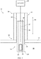
- Fig. 1 illustrates a schematic cross sectional view of apparatus 10 and an object 12 according to various examples.
- the apparatus 10 includes a first tube 14, a member 16, a heat pipe 18, and an actuator 20.
- the object 12 may be any article, module, component, part, or assembly of components that define a cavity 22 and an opening 24 to the cavity 22.
- the object 12 may be a gas turbine engine or a module of a gas turbine engine.
- the object 12 may be an internal combustion engine for a vehicle.
- the object 12 may be a pipeline, a storage tank, or other container.
- the opening 24 may be a borescope port and the cavity 22 may be a gas path within the gas turbine engine.
- the apparatus 10 may be inserted into the cavity 22 of the object 12 via the opening 24 to enable an inspection, a repair activity, or a non-destructive examination to be performed.
- the heat pipe 18 is arranged to transfer thermal energy from the member 16 and may thereby prevent the member 16 from being damaged by high temperatures within the cavity 22.
- the first tube 14 extends along a longitudinal axis 27 and includes a first end 26 and a second opposite end 28.
- the first tube 14 may have any suitable cross sectional shape and may have, for example, a circular, elliptical, or a polygonal cross sectional shape.
- the first tube 14 also includes a first cavity 30 that extends between the first end 26 and the second end 28 along the longitudinal axis 27.
- the first cavity 30 extends from the first end 26 to the second end 28 and the first end 26 and the second end 28 may be open.
- the first cavity 30 has a length along the longitudinal axis 27 that is less than the length of the first tube 14 along the longitudinal axis 27 and consequently, the first end 26 and/or the second end 28 may be closed.
- the first tube 14 may also include an aperture 32 that provides an opening to the cavity 30.
- the aperture 32 may have any suitable shape and may be circular, elliptical or have a polygonal shape for example.
- the aperture 32 may be located at the second end 28 of the first tube 14 as illustrated in Fig. 1 . In other examples, the aperture 32 may be located at any position between the first end 26 and the second end 28.
- the aperture 32 may be an open aperture or may be covered by a material that is transparent to electromagnetic waves within one or more portions of the electromagnetic spectrum. For example, the aperture 32 may be covered by glass that is transparent to light.
- the member 16 may be positioned within the first cavity 30 of the first tube 14 and may be positioned adjacent the aperture 32 of the first tube 14. In some examples, the member 16 may completely cover the aperture 32 (and may or may not seal the aperture 32). In other examples, the member 16 may only partially cover the aperture 32.
- the member 16 is configured to enable one or more actions to be performed. The actions may include (but are not limited to) an inspection activity, and/or a repair activity, and/or a machining activity and these are described in greater detail in the following paragraphs.
- the member 16 may comprise inspection apparatus for enabling the interior of the object 12 to be inspected by a human operator and/or a computer.
- the member 16 may comprise an optical sensor (such as a charge coupled device (CCD) camera, or a complementary metal oxide semiconductor (CMOS) camera) at the second end 28 of the first tube 14 to enable electromagnetic waves to be received via the aperture 32 and/or the second end 28 (where the second end 28 is open).
- the member 16 may also comprise a device for emitting electromagnetic waves (such as a laser, a light emitting diode, a halogen bulb for example) positioned at the second end 28 to enable electromagnetic waves to be emitted from the aperture 32 and/or the second end 28 (where the second end 28 is open).
- the optical sensor and the emitter may be connected to a processor and memory positioned outside of the first cavity 30 via one or more cables.
- the member 16 may comprise one or more nozzles for injecting an inspection fluid into the cavity 22 of the object 12.
- the member 16 may additionally comprise one or more nozzles for injecting water into the cavity 22 of the object 12.
- the member 16 may comprise one or more optical fibres to enable electromagnetic waves to be transmitted from the aperture 32 (and/or open second end 28 of the first tube 14) and/or to enable electromagnetic waves to be received via the aperture 32 (and/or open second end 28 of the first tube 14).
- the apparatus 10 may further comprise an optical sensor (such as a charge coupled device (CCD) camera, or a complementary metal oxide semiconductor (CMOS) camera) coupled to the one or more optical fibres.
- the optical sensor may be positioned external to the first tube 14 or may be positioned internal to the first tube 14 (at the first end 26 of the first tube 14 for example).
- the apparatus 101 may also comprise a device for emitting electromagnetic waves (such as a laser, a light emitting diode, a halogen bulb for example) that is coupled to the one or more optical fibres.
- the device for emitting electromagnetic waves may be positioned external to the first tube 14 or may be positioned internal to the first tube 14 (for example, at the first end 26 of the first tube 14).
- the member 16 may comprise repair apparatus for performing a repair on the object 12.
- the apparatus 16 may comprise one or more optical fibres and a laser as described in the preceding paragraph to enable the apparatus 10 to clean the object 12 or to drill the object 12.
- the member 16 may comprise one or more nozzles for spraying a coating on the object 12.
- the member 16 may comprise one or more nozzles and a pump for extracting fluid from the cavity 22 of the object 12 (for example, to create a vacuum in the cavity 22).
- the member 16 may comprise one or more nozzles for injecting a braze into the cavity 22 of the object 12.
- the member 16 may comprise non-destructive examination (NDE) apparatus (which may also be referred to as non-destructive testing (NDT) apparatus).
- NDE non-destructive examination
- the member 16 may comprise one or more optical fibres, a sensor (as described above) and a computer for enabling non-destructive examination to be performed.
- the member 16 may comprise an ultrasonic transducer and a computer for enabling non-destructive examination to be performed.
- the member 16 may comprise infrared and thermal testing apparatus for enabling non-destructive examination to be performed. It should be appreciated that the member 16 may comprise any suitable non-destructive examination apparatus and is not limited to the examples provided above.
- the heat pipe 18 may be any suitable heat pipe or thermosiphon and may also be referred to as a second tube.
- the heat pipe 18 may be coated with any suitable material.
- the heat pipe 18 may be coated with a nickel alloy.
- the heat pipe 18 includes a first end 34 and an opposite second end 36.
- the heat pipe 18 may have any suitable cross sectional shape (when viewed in plan) and may have a circular cross sectional shape, an elliptical cross sectional shape, or a polygonal cross sectional shape.
- the heat pipe 18 may be shaped and sized to not fit within the opening 24 of the object 12 and consequently, the heat pipe 18 may abut the outer surface of the object 12 (as illustrated in Fig. 1 ). In other examples, the heat pipe 18 may be shaped and sized to fit within the opening 24 of the object 12.
- the heat pipe 18 defines a second cavity 38 that extends between the first end 34 and the second end 36 of the heat pipe 18. As illustrated in Fig. 1 , the first end 34 and the second end 36 are open and the first tube 14 is positioned within the second cavity 38 of the heat pipe 18. In some examples, the first tube 14 and the heat pipe 18 are arranged concentrically and share the longitudinal axis 27. In other examples, the first tube 14 and the heat pipe 18 are not arranged concentrically and consequently have separate longitudinal axes.
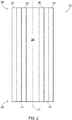
- the heat pipe 18 may include: an inner region 40; an outer region 42; a channel 44 between the inner region 40 and the outer region 42; and a fluid.
- the inner region 40 and the outer region 42 may have any suitable dimensions.
- the inner region 40 and/or the outer region 42 may have a thickness (as measured perpendicular to the longitudinal axis 27) in the range of one hundred micrometres to three thousand micrometres.
- the inner region 40 and/or the outer region 42 may have a thickness in the range of three hundred micrometres to one thousand micrometres. It should be appreciated that the inner region 40 and the outer region 42 may have the same thickness, or may have different thicknesses.
- the fluid may be any suitable fluid for a heat pipe.
- the fluid may be: an alkali metal (for example, caesium, potassium, and sodium) or an alloy of alkali metal (such as NaK); an organic compound (for example, naphthalene, acetone, hydrocarbons such as ethane, alcohols such as methanol, and amines such as methylamine); a transition metal (mercury or silver for example); a post-transition metal (such as indium); water; or ammonia.
- an alkali metal for example, caesium, potassium, and sodium
- an alloy of alkali metal such as NaK
- an organic compound for example, naphthalene, acetone, hydrocarbons such as ethane, alcohols such as methanol, and amines such as methylamine
- a transition metal mercury or silver for example
- a post-transition metal such as indium
- water or ammonia.
- the fluid flows as a liquid between the first end 34 and the second end 36 in the inner region 40 and the outer region 42, and flows as a vapour between the first end 34 and the second end 36 in the channel 44.
- the fluid flows as a liquid from the first end 34 to the second end 36 in the inner region 40 and the outer region 42, vaporises at the second end 36, flows as a vapour from the second end 36 to the first end 34 in the channel 44, and then condenses at the first end 34.
- the fluid may flow as a liquid in the inner region 40 and the outer region 42 via capillary action.
- the inner region 40 and/or the outer region 42 may comprise a lattice structure 46 defining a plurality of pores 47 as illustrated in Fig. 3 .
- the lattice structure 46 includes a plurality of nodes 48, and a plurality of links 50 that extend between the plurality of nodes 48 and define the plurality of pores 47.
- the lattice structure 46 may be manufactured using an additive layer manufacturing (ALM) technique such as Selective Laser Melting (SLM).
- ALM additive layer manufacturing
- SLM Selective Laser Melting
- the lattice structure 46 may be manufactured using an alternative manufacturing process.
- the lattice structure 46 may be manufactured by wrapping a mesh multiple times around the inside of a tube.
- the lattice structure 46 may be manufactured using laser drilling.
- the lattice structure 46 may be manufactured by poorly sintering a powder.
- the lattice structure 46 may be manufactured using a powder sintering process.
- adjacent nodes in the plurality of nodes 48 define a height (H) 52, a width (W) 54, and a depth (D) 56 and thus define the dimensions of the plurality of pores 47.
- the height (H) 52, the width (W) 54 and the depth (D) 56 may be the same as one another, or may be different to one another.
- the dimensions of the plurality of pores 47 may vary between different nodes 48.
- the width (W) 54 between adjacent nodes 48 may increase or decrease between the first end 34 and the second end 36 of the heat pipe 18.
- the plurality of pores 47 have a median dimension (that is, height (H) 52, and/or width (W) 54, and/or depth (D) 56) in the range of five micrometres to two hundred and fifty micrometres and may have a median dimension in the range of thirty micrometres to one hundred and twenty micrometres.
- the inner region 40 and/or the outer region 42 may be relatively thin and may have a thickness in the range of five hundred micrometres to one thousand micrometres (measured perpendicularly to the longitudinal axis 27). Consequently, the inner region 40 and/or the outer region 42 may advantageously have relatively low capillary losses.
- the inner region 40 and/or the outer region 42 may comprise a plurality of grooves 58 as illustrated in Fig. 4 .
- the plurality of grooves 58 are oriented parallel to the longitudinal axis 28 and extend between the first end 34 and the second end 36 of the heat pipe 18.
- the plurality of grooves 58 may be formed through an additive layer manufacturing (ALM) process such as selective layer melting (SLM).
- ALM additive layer manufacturing
- SLM selective layer melting
- the plurality of grooves 58 may be hollow, or may comprise the lattice structure 46 therein.
- the grooves 58 may have a width (measured perpendicular to the longitudinal axis 27) in the range of fifty micrometres to three hundred micrometres.
- the gaps between adjacent grooves 58 may have a width (also measured perpendicular to the longitudinal axis 27) in the range of fifty micrometres to three hundred micrometres.
- the regions adjacent to the plurality of grooves 58 within the inner region 40 and the outer region 42 may be solid, or may be porous and comprise the lattice structure described in the preceding paragraphs.
- the gaps between adjacent grooves 58 may be open, or may comprise a porous structure (such as the lattice structure described in the preceding paragraphs).
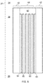
- the channel 44 may comprise a plurality of conduits 60 that are interconnected at the first end 34 of the heat pipe 18 to form a chamber 62 as illustrated in Fig. 5 .
- the plurality of conduits 60 are oriented parallel to the longitudinal axis 27 and extends between the first end 34 and the second end 36 of the heat pipe 18.
- the channel 44 may provide an advantage in that liquid may flow from the first end 34 to the second end 36 via the plurality of conduits 60, vaporise, and then return to the first end 34 via adjacent conduits 64 (which may comprise the lattice structure 46).
- the actuator 20 may include any suitable device for moving the first tube 14 relative to the heat pipe 18.
- the actuator 20 may include a servomotor, a hydraulic cylinder, a pneumatic cylinder, a rack and pinion, a cam rotatable on a shaft, or a lead screw.
- the actuator 20 is configured to move the first tube 14 relative to the heat pipe 18 and parallel to the longitudinal axis 27 as indicated by arrow 66.
- the actuator 20 may be configured to move the first tube 14 between a first position in which the member 16 is located within the cavity 22 (and outside of the heat pipe 18), and a second position in which the member 16 is located within the heat pipe 18 (and may not be located within the cavity 22).
- the apparatus 10 may provide several advantages. First, the apparatus 10 may enable an action (such as inspection, repair, non-destructive examination) to be performed within the cavity 22 of the object 12 when the member 16 is positioned within the cavity 22 (that is, when the first tube 14 is in the first position). Second, the heat pipe 18 may transfer thermal energy from the member 16 when the first tube 14 is in the second position. This may allow the apparatus 10 to be coupled to the object 12 when the object 12 is in operation and the cavity 22 is at a relatively high temperature. The heat pipe 18 may thus prevent the member 16 from being damaged by the relatively high temperatures in the cavity 22. In some examples, the apparatus 10 may advantageously be used when the object 12 is in operation (for example, during start-up of a gas turbine engine) and the temperature within the cavity 22 is within the operating temperature range of the member 16.
- an action such as inspection, repair, non-destructive examination
- Fig. 6 illustrates a schematic side view of another apparatus 101 and an object 12.
- the apparatus 101 is similar to the apparatus 10 illustrated in Fig. 1 and where the features are similar, the same reference numerals are used.
- the apparatus 101 differs from the apparatus 10 in that the apparatus 101 further comprises a heat pipe 181, a plug 68, a connector arrangement 70, one or more optical fibres 71, a light source 72, and an optical sensor 74.
- the heat pipe 181 differs from the heat pipe 18 illustrated in Fig. 1 in that the heat pipe 181 comprises a first part 182 extending along the longitudinal axis 27 and includes the second cavity 38, and also a second part 183 extending along a second longitudinal axis 76.
- the second longitudinal axis 76 defines an angle 78 with the first longitudinal axis 27.
- the second longitudinal axis 76 defines an angle 78 of ninety degrees with the first longitudinal axis 27.
- the angle 78 may be any acute angle or any obtuse angle.
- the first part 181 and/or the second part 182 may be curved along at least a portion of their lengths in other examples.
- the second part 183 of the heat pipe 181 may extend from the first end 34 of the first part 182 of the heat pipe 181 as illustrated in Fig. 6 . In other examples, the second part 183 of the heat pipe 181 may extend from first part 182 of the heat pipe 181 at any location between the first end 34 and the second end 36.
- the second part 183 may have the same structure, or a different structure to the first part 182. Therefore, the second part 183 may have an internal structure as illustrated in any of Figs. 2 , 3 , 4 , and 5 .
- the second part 183 may include a channel surrounded by porous regions (as illustrated in Fig. 3 ) or grooved regions (as illustrated in Fig. 4 ).
- the channel may be hollow or may have the structure illustrated in Fig. 5 (that is, the channel may comprise a plurality of conduits interconnected by a chamber).
- the channel of the second part 183 is connected to the channel 44 of the first part 182, and the porous regions/grooved regions of the second part 183 are connected to the inner and outer regions 40, 42 of the first part 182.
- first part 182 and the second 183 comprise grooved regions, it should be appreciated that the grooved regions are connected to one another to permit move of fluid between the first part 182 and the second part 183.
- the second part 183 may comprise a device 77 for increasing the transfer of thermal energy from the second part 183.
- the device may comprise a heat sink 77 that increases the transfer of thermal energy from the second part 183.
- the heat sink 77 may be positioned at the free end of the second part 183 (that is, the end opposite to the end that is coupled to the first part 182).
- the heat sink 77 may have any suitable structure and may comprise a plurality of conductive fins that extend radially outwards from the second part 183.
- the device may comprise a Peltier cooler 77 to increase the transfer of thermal energy from the second part 183.
- the device may additionally or alternatively comprise a thermal electric generator 77 to create electrical energy from the dissipation of thermal energy.
- the second part 183 of the heat pipe 181 may advantageously enable thermal energy from the member 16 to be transferred to a relatively cool location that is not positioned along the longitudinal axis 27 of the first part 182 of the heat pipe 181.
- the second part 183 of the heat pipe 181 may extend towards and into a bifurcation tube within the bypass duct of the gas turbine engine.
- the object 12 includes a first wall 121 and a second wall 122 (which may be casing walls of a gas turbine engine for example).
- the first end 34 of the first part 182 of the heat pipe 181 extends through an opening 76 in the first wall 121 and the second end 36 of the first part 182 of the heat pipe 181 abuts an exterior surface of the second wall 122 around an opening 24 in the second wall 122.
- the plug 68 is coupled to the second end 28 of the first tube 14.
- the plug 68 may be coupled to the second end 28 via an adhesive.
- the plug 68 may be welded to the first tube 14.
- the plug 68 may be integral with the first tube 14 and may define the second end 28 of the first tube 14.
- the plug 68 may be sized and shaped to plug the opening 24 of the object 12 and thereby seal the cavity 22.
- the plug 68 may be sized and shaped to plug the borescope port and thereby seal the gas path within the gas turbine engine.
- the plug 68 may be sized and shaped to plug the open second end 36 of the heat pipe 181 (for example, in an embodiment where the second end 36 of the heat pipe 181 protrudes through the opening 24 and into the cavity 22).
- the connector arrangement 70 is configured to connect the apparatus 101 to the object 12.
- the connector arrangement 70 comprises a plurality of fasteners 80 (such as screws or bolts) that extend through a ring 82 extending radially outwards from the first part 182 of the heat pipe 181 and into the first wall 121 of the object 12.
- the connector arrangement 70 may include an alternative mechanism for connecting the apparatus 101 to the object 12 and may include an adhesive for example. Consequently, the heat pipe 181 may be fixed to the first wall 121 and be static relative to the first wall 121.
- the connector arrangement 70 may be configured to enable an operator to connect the apparatus 101 to the object 12, and to enable the operator to disconnect and remove the apparatus 70 from the object 12.
- the connector arrangement 70 comprises a plurality of fasteners 80 as illustrated in Fig. 6
- the operator may use a wrench to tighten the fasteners 80 to connect the apparatus 101 to the object 12.
- the operator may use the wrench to loosen the plurality of fasteners 80 to disconnect the apparatus 101 from the object 12, and may then remove the apparatus 101 by hand, or by using a mechanical aid (such as a pulley system).
- the plurality of optical fibres 71 have a first end positioned at the aperture 32 of the first tube 14 (and may be coupled to a lens within the aperture 32), and a second end connected to the optical sensor 74 and the light source 72.
- the optical sensor 74 and the light source 72 are positioned externally of the first tube 14 and consequently, the plurality of optical fibres 71 include a first part that extends along the length of the first tube 14 within the first cavity 30 between the aperture 32 and the first end 26 of the first tube 14, and a second part that extends from the first end 26 of the first tube 14 to the optical sensor 74 and the light source 72.
- the light source 72 may be any suitable emitter of visible light and may comprise a light emitting diode or a laser. In some examples, the light source 72 may be configured to emit infrared radiation or ultraviolet radiation. While the light source 72 is illustrated as being positioned external to the first tube 14 in Fig. 6 , it should be appreciated that in other examples, the light source 72 may be positioned within the first cavity 30 of the first tube 14 (at the aperture 32 for example).
- the optical sensor 74 may be any suitable optical sensor and may be a charge coupled device (CCD) camera or a complementary metal oxide semiconductor (CMOS) camera for example. While the optical sensor 74 is illustrated as being positioned external to the first tube 14 in Fig. 6 , it should be appreciated that in other examples, the optical sensor 74 may be positioned within the first cavity 30 of the first tube 14 (at the aperture 32 for example).
- CCD charge coupled device
- CMOS complementary metal oxide semiconductor
- the light source 72 is configured to emit light which is conveyed to the aperture 32 of the first tube 14 via the plurality of optical fibres 71.
- the plurality of optical fibres 71 direct the light out of the aperture 32 and into the cavity 22 of the object 12. The light is then reflected by the surfaces of the object 12 and some of the reflected light is received at the aperture 32 which is conveyed to the optical sensor 74 via the plurality of optical fibres 71.
- the actuator 20 is configured to move the first tube 14 between a first position in which the plug 68 seals the member 16 from the cavity 22 of the object 12, and a second position in which the member 16 is exposed to the cavity 22 of the object 12 (as illustrated in Fig. 6 ).
- the first position may be achieved by the plug 68 forming a seal with the opening 24, or by the plug 68 forming a seal with the second open end 36 of the heat pipe 181.
- the apparatus 181 may provide several advantages.
- the plug 68 may provide an effective seal with the object 12 or with the heat pipe 181 and may consequently protect the member 16 from being damaged by fluids within the cavity 20 of the object 12.
- the plug 68 may be sized and dimensioned to fit snugly inside the opening 24 of the object 12 and consequently, the object 12 may not require modification to be used with the apparatus 101.
- the plug 68 may not comprise any movable mechanical parts and consequently, the plug 68 may be relatively simple and may be less likely to fail during operation.
- the remote positioning of a sensor from the first tube 14 (such as the optical sensor 74 and the first tube 14 illustrated in Fig. 6 ) may provide more space for the sensor and thereby allow the sensor to have a larger sensor area with a higher resolution.
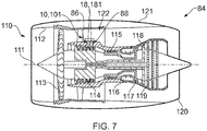
- Figure 7 illustrates a schematic cross sectional side view of a system 84 comprising a gas turbine engine 110 and apparatus 10, 101 as described in the preceding paragraphs.
- the gas turbine engine 110 has a principal and rotational axis 111 and comprises, in axial flow series, an air intake 112, a propulsive fan 113, an intermediate pressure compressor 114, a high-pressure compressor 115, combustion equipment 116, a high-pressure turbine 117, an intermediate pressure turbine 118, a low-pressure turbine 119 and an exhaust nozzle 120.
- a nacelle 121 generally surrounds the engine 110 and defines both the intake 112 and the exhaust nozzle 120.
- the gas turbine engine 110 operates so that air entering the intake 112 is accelerated by the fan 113 to produce two air flows: a first air flow into the intermediate pressure compressor 114 and a second air flow which passes through a bypass duct 122 to provide propulsive thrust.
- the intermediate pressure compressor 114 compresses the air flow directed into it before delivering that air to the high pressure compressor 115 where further compression takes place.
- the compressed air exhausted from the high-pressure compressor 115 is directed into the combustion equipment 116 where it is mixed with fuel and the mixture combusted.
- the resultant hot combustion products then expand through, and thereby drive the high, intermediate and low-pressure turbines 117, 118, 119 before being exhausted through the nozzle 120 to provide additional propulsive thrust.
- the high 117, intermediate 118 and low 119 pressure turbines drive respectively the high pressure compressor 115, intermediate pressure compressor 114 and fan 113, each by a suitable interconnecting shaft.
- gas turbine engines to which the present disclosure may be applied may have alternative configurations.
- such engines may have an alternative number of interconnecting shafts (two for example) and/or an alternative number of compressors and/or turbines.
- the gas turbine engine may comprise a gearbox provided in the drive train from a turbine to a compressor and/or fan.
- the gas turbine engine 110 includes a first inspection port 86 and the apparatus 10, 101 extends inside the first inspection port 86.
- the second end 36 of the heat pipe 18, 181 extends into the gas path of the gas turbine engine 110 and the first end 34 of the heat pipe 18, 181 is positioned within the bypass duct 122 of the gas turbine engine 110.
- the gas turbine engine 110 may further comprise a second inspection port 88, and the system 84 may further comprise another apparatus 10, 101 that extends inside the second inspection port 88.
- the second end 36 of the heat pipe 18, 181 may extend into the gas path of the gas turbine engine 110 and the first end 34 of the heat pipe 18, 181 may be positioned within the bypass duct 122 of the gas turbine engine 110.
- an apparatus may comprise any one of, or any combination of, the plug 68, the connector arrangement 70, the one or more optical fibres 71, the light source 72, and the optical sensor 74.
- the heat pipe 18, 181 may include a single loop instead of the structure illustrated in Fig. 2 .
- the single loop may include a relatively long, thin cavity that is looped from the first end 34 to the second end 36. In a first part of the loop there are pores or grooves without a vapour gap 44, and in a second part of the loop there is a hollow cavity without pores or grooves to allow the vapour to travel to the first end 34 for condensation.
- the heat pipe 18, 181 may include a plurality of such loops, or may include a single loop that spirals around. In the example of the heat pipe 181, the one or more loops may extend into the second part 183 where the fluid is condensed.
- the heat pipe 18, 181 may use a single phase approach (a liquid for example) rather than a two-phase evaporation and condensation approach.
- the liquid receives thermal energy at the second end 36 of the heat pipe 18, 181 and transfers thermal energy away at the first end 34 of the heat pipe 18 or in the second part 183 of the heat pipe 181.
- the member 16 may be positioned on the exterior of the first tube 14 and the first tube 14 may not define the first cavity 30 (for example, the first tube 14 may be solid).
Landscapes
- Physics & Mathematics (AREA)
- Engineering & Computer Science (AREA)
- General Physics & Mathematics (AREA)
- Mechanical Engineering (AREA)
- General Engineering & Computer Science (AREA)
- Optics & Photonics (AREA)
- Astronomy & Astrophysics (AREA)
- Chemical & Material Sciences (AREA)
- Life Sciences & Earth Sciences (AREA)
- Health & Medical Sciences (AREA)
- Biochemistry (AREA)
- General Health & Medical Sciences (AREA)
- Analytical Chemistry (AREA)
- Immunology (AREA)
- Pathology (AREA)
- Combustion & Propulsion (AREA)
- Thermal Sciences (AREA)
- Sustainable Development (AREA)
- Investigating Materials By The Use Of Optical Means Adapted For Particular Applications (AREA)
Claims (14)
- Appareil (10, 101) destiné à être inséré dans une cavité (22) d'un objet (12), l'appareil comprenant :un premier tube (14) comprenant une première extrémité (26), une seconde extrémité (28) et une première cavité (30) s'étendant entre la première extrémité (26) et la seconde extrémité (28);un élément (16) positionné à l'intérieur de la première cavité (30) du premier tube (14) et conçu pour permettre la réalisation d'une action ;un caloduc (18, 181) comprenant une première extrémité (34), une seconde extrémité (36) et une seconde cavité (38) s'étendant entre la première extrémité (34) et la seconde extrémité (36), le premier tube (14) étant positionné à l'intérieur de la seconde cavité (38) du caloduc (18, 181), le caloduc (18, 181) étant agencé pour transférer de l'énergie thermique à partir de l'élément (16) pour empêcher l'élément (16) d'être endommagé par des températures élevées à l'intérieur de la cavité (22) de l'objet (12) ; etun actionneur (20) conçu pour déplacer le premier tube (14) par rapport au caloduc (18, 181).
- Appareil selon la revendication 1, ledit caloduc (181) comprenant une première partie (182) s'étendant le long d'un premier axe longitudinal (27) et comprenant la seconde cavité (38), et une seconde partie (183) s'étendant le long d'un second axe longitudinal (76), le second axe longitudinal (76) définissant un angle (78) avec le premier axe longitudinal (27).
- Appareil selon la revendication 2, ledit second axe longitudinal (76) définissant un angle de quatre-vingt-dix degrés avec le premier axe longitudinal (27).
- Appareil selon l'une quelconque des revendications précédentes, ledit caloduc (18, 181) comprenant : une zone interne (40) pour permettre au fluide de s'écouler vers la seconde extrémité (36) du caloduc (18, 181) ; une zone externe (42) pour permettre au fluide de s'écouler vers la seconde extrémité (36) du caloduc (18, 181) ; et un canal (44) pour permettre à la vapeur de s'écouler vers la première extrémité (34) du caloduc (18, 181).
- Appareil selon la revendication 4, ladite zone interne (40) comprenant une structure en treillis (46) définissant une pluralité de pores (47), et/ou ladite zone externe (42) comprenant une structure en treillis (46) définissant une pluralité de pores (47).
- Appareil selon la revendication 4 ou 5, ladite zone interne (40) comprenant une pluralité de rainures (58) et ladite zone externe (42) comprenant une pluralité de rainures (58).
- Appareil selon l'une quelconque des revendications 4 à 6, ledit canal (44) comprenant une pluralité de conduits (60) qui sont reliés à la première extrémité (34) du caloduc (18, 181).
- Appareil selon l'une quelconque des revendications précédentes, comprenant en outre un bouchon (68) couplé à la seconde extrémité (28) du premier tube (14), l'actionneur (20) étant conçu pour déplacer le premier tube (14) entre un première position dans laquelle le bouchon (68) assure l'étanchéité de l'élément (16) par rapport à la cavité (22) de l'objet (12), et une seconde position dans laquelle l'élément (16) est exposé à la cavité (22) de l'objet (12).
- Appareil selon l'une quelconque des revendications précédentes, comprenant en outre un agencement de raccord (70) conçu pour raccorder l'appareil (10, 101) à l'objet (12), l'agencement de raccord (70) étant conçu pour permettre à un opérateur de raccorder l'appareil (10, 101) à l'objet (12), et pour permettre à l'opérateur de séparer et de retirer l'appareil (10, 101) de l'objet (12).
- Appareil selon l'une quelconque des revendications précédentes, ledit élément (16) comprenant une ou plusieurs fibres optiques (71), et ledit appareil comprenant en outre un capteur optique (74) couplé à la ou aux fibres optiques (71), le capteur optique (74) étant positionné à l'extérieur du premier tube (14).
- Appareil selon l'une quelconque des revendications 1 à 9, ledit élément (16) comprenant un capteur optique, ou ledit élément comprenant un appareil de réparation destiné à effectuer une réparation sur l'objet, ou ledit élément comprenant un appareil d'examen non destructif (NDE).
- Appareil selon l'une quelconque des revendications précédentes, ledit objet (12) étant un moteur à turbine à gaz (110), la cavité (22) étant un trajet de gaz du moteur à turbine à gaz (110).
- Système (84) comprenant : un moteur à turbine à gaz (110) comprenant un premier orifice d'inspection (86) ; et un appareil (10, 101) selon l'une quelconque des revendications précédentes s'étendant à l'intérieur du premier orifice d'inspection (86).
- Système selon la revendication 13, ladite première extrémité (34) du caloduc (18, 181) étant positionnée à l'intérieur d'un conduit de dérivation (122) du moteur à turbine à gaz (110).
Applications Claiming Priority (1)
| Application Number | Priority Date | Filing Date | Title |
|---|---|---|---|
| GBGB1615429.6A GB201615429D0 (en) | 2016-09-12 | 2016-09-12 | Apparatus for insertion into a cavity of an object |
Publications (2)
| Publication Number | Publication Date |
|---|---|
| EP3293514A1 EP3293514A1 (fr) | 2018-03-14 |
| EP3293514B1 true EP3293514B1 (fr) | 2021-02-17 |
Family
ID=57234680
Family Applications (1)
| Application Number | Title | Priority Date | Filing Date |
|---|---|---|---|
| EP17186862.3A Active EP3293514B1 (fr) | 2016-09-12 | 2017-08-18 | Appareil d'insertion dans la cavité d'un objet |
Country Status (3)
| Country | Link |
|---|---|
| US (1) | US10472984B2 (fr) |
| EP (1) | EP3293514B1 (fr) |
| GB (1) | GB201615429D0 (fr) |
Families Citing this family (3)
| Publication number | Priority date | Publication date | Assignee | Title |
|---|---|---|---|---|
| US11525359B1 (en) * | 2021-05-28 | 2022-12-13 | Raytheon Technologies Corporation | Heat pipe for a turbine engine |
| GB202207505D0 (en) | 2022-05-23 | 2022-07-06 | Rolls Royce Plc | System for use with component of power generation apparatus |
| US12486800B2 (en) | 2024-04-19 | 2025-12-02 | Rtx Corporation | Powerplant with integrated heat pipe |
Family Cites Families (31)
| Publication number | Priority date | Publication date | Assignee | Title |
|---|---|---|---|---|
| DE2515753A1 (de) * | 1975-04-10 | 1976-10-14 | Siemens Ag | Waermerohr |
| GB2090333B (en) | 1980-12-18 | 1984-04-26 | Rolls Royce | Gas turbine engine shroud/blade tip control |
| US4461343A (en) * | 1982-01-28 | 1984-07-24 | Mcdonnell Douglas Corporation | Plated heat pipe |
| AT384108B (de) * | 1983-06-08 | 1987-10-12 | Avl Verbrennungskraft Messtech | Einrichtung zur feststellung der vorgaenge im brennraum einer in betrieb befindlichen brennkraftmaschine |
| US6080962A (en) | 1996-12-20 | 2000-06-27 | Trw, Inc. | Self-contained thermal control for a spacecraft module |
| US6091489A (en) * | 1998-02-25 | 2000-07-18 | Welker Engineering Company | Optical inspection apparatus for pressurized vessels |
| US5979220A (en) | 1998-06-30 | 1999-11-09 | Siemens Westinghouse Power Corporation | In-situ sensors for gas turbines |
| US6749395B1 (en) * | 1999-07-29 | 2004-06-15 | Siemens Aktiengesellschaft | Device and method for controlling a cooling air flow of a gas turbine |
| US6233937B1 (en) * | 2000-09-20 | 2001-05-22 | Siemens Westinghouse Power Corporation | Cooling spray application to a turbine and exhaust region of a steam turbine |
| US6364003B1 (en) | 2001-05-23 | 2002-04-02 | Ming-Hwa Liu | Device and method for absorbing and radiating heat in very small space by alternately pushing two fluids |
| WO2006002522A1 (fr) | 2004-06-30 | 2006-01-12 | Trojan Technologies Inc. | Dispositif a capteur de rayonnement et systeme de traitement de fluides contenant ce dispositif |
| WO2006007721A1 (fr) * | 2004-07-21 | 2006-01-26 | Xiao Huang | Materiaux a effet meche hybrides conçus pour etre utilises dans des caloducs haut rendement |
| US7313963B2 (en) | 2006-02-28 | 2008-01-01 | General Electric Company | Isothermal de-iced sensor |
| CN100582638C (zh) * | 2006-04-14 | 2010-01-20 | 富准精密工业(深圳)有限公司 | 热管 |
| CN100498186C (zh) * | 2006-06-02 | 2009-06-10 | 富准精密工业(深圳)有限公司 | 热管 |
| US7900438B2 (en) | 2006-07-28 | 2011-03-08 | General Electric Company | Heat transfer system and method for turbine engine using heat pipes |
| US8015788B2 (en) * | 2006-12-27 | 2011-09-13 | General Electric Company | Heat transfer system for turbine engine using heat pipes |
| US8366609B2 (en) * | 2007-09-18 | 2013-02-05 | Olympus Medical Systems Corp. | Actuator and image pickup apparatus |
| US8353334B2 (en) | 2007-12-19 | 2013-01-15 | Teledyne Scientific & Imaging, Llc | Nano tube lattice wick system |
| US8397516B2 (en) * | 2009-10-01 | 2013-03-19 | General Electric Company | Apparatus and method for removing heat from a gas turbine |
| JP5714836B2 (ja) * | 2010-04-17 | 2015-05-07 | モレックス インコーポレイテドMolex Incorporated | 熱輸送ユニット、電子基板、電子機器 |
| US20120227925A1 (en) * | 2011-03-08 | 2012-09-13 | Daniel Sweeney | Thermal energy storage system with heat energy recovery sub-system |
| US20130168052A1 (en) * | 2011-12-30 | 2013-07-04 | Celsia Technologies Taiwan, Inc. | Heat pipe and composition of capillary wick thereof |
| US9217852B2 (en) | 2012-01-31 | 2015-12-22 | Siemens Energy, Inc. | System and method for online inspection of turbines using an optical tube with broadspectrum mirrors |
| US9028206B2 (en) * | 2012-06-12 | 2015-05-12 | General Electric Company | Thermally actuated assembly for a gas turbine system and method of controlling a cooling airflow path |
| US20140034848A1 (en) * | 2012-08-03 | 2014-02-06 | Brian Campbell | Photon turbine generator for power generation |
| CA2891549A1 (fr) * | 2012-11-30 | 2014-08-28 | General Electric Company | Ensemble moteur de turbine et systeme d'aeronef a double combustible |
| US9797310B2 (en) * | 2015-04-02 | 2017-10-24 | General Electric Company | Heat pipe temperature management system for a turbomachine |
| US9909448B2 (en) * | 2015-04-15 | 2018-03-06 | General Electric Company | Gas turbine engine component with integrated heat pipe |
| US10694641B2 (en) * | 2016-04-29 | 2020-06-23 | Intel Corporation | Wickless capillary driven constrained vapor bubble heat pipes for application in electronic devices with various system platforms |
| GB2553144B (en) * | 2016-08-26 | 2019-10-30 | Rolls Royce Plc | Apparatus for insertion into a cavity of an object |
-
2016
- 2016-09-12 GB GBGB1615429.6A patent/GB201615429D0/en not_active Ceased
-
2017
- 2017-08-18 EP EP17186862.3A patent/EP3293514B1/fr active Active
- 2017-08-18 US US15/680,619 patent/US10472984B2/en active Active
Non-Patent Citations (1)
| Title |
|---|
| None * |
Also Published As
| Publication number | Publication date |
|---|---|
| US20180163561A1 (en) | 2018-06-14 |
| US10472984B2 (en) | 2019-11-12 |
| GB201615429D0 (en) | 2016-10-26 |
| EP3293514A1 (fr) | 2018-03-14 |
Similar Documents
| Publication | Publication Date | Title |
|---|---|---|
| EP3287771B1 (fr) | Appareil d'insertion dans la cavité d'un objet | |
| EP3293514B1 (fr) | Appareil d'insertion dans la cavité d'un objet | |
| CN107203036B (zh) | 用于燃气涡轮发动机的光学成像系统 | |
| US10393303B2 (en) | Threaded fitting for tube | |
| CN104254671B (zh) | 与管一体的半套管式金属密封件 | |
| EP3730743B1 (fr) | Tube à parois multiples et raccord pour l'alimentation en huile de palier | |
| FR3078367A1 (fr) | Turbomachine comportant un echangeur de chaleur dans la veine secondaire | |
| EP3358140B1 (fr) | Raccord pour tube à parois multiples | |
| CN101135250A (zh) | 用于涡轮机的基于热导管的冷却设备及方法 | |
| US10450892B2 (en) | Thermal management of turbine casing using varying working mediums | |
| JP2017142244A (ja) | タービンエンジン構成要素を検査するための光学装置およびサイトチューブ | |
| US11274601B2 (en) | Internal fuel/air heat exchangers | |
| FR3065490A1 (fr) | Ensemble propulsif pour aeronef comportant des echangeurs de chaleur air-liquide | |
| CA2639209C (fr) | Ventilation et pressurisation de composants dans une turbomachine | |
| US10392968B2 (en) | Turbine casing cooling structure | |
| US10598094B2 (en) | Heat pipe temperature management system for wheels and buckets in a turbomachine | |
| FR3104691A1 (fr) | Echangeur de chaleur comportant une paroi perturbatrice à générateurs de turbulence creux | |
| CN120906690A (zh) | 涡轮发动机预冷系统及飞行器 | |
| US20160100503A1 (en) | Systems and methods for cooling a probe disposed about a hot gas path | |
| US20200282574A1 (en) | Sensor | |
| CN101893154A (zh) | 涉及通过通路输送流体的装置、方法和/或系统 | |
| US10344983B2 (en) | Assembly of tube and structure crossing multi chambers | |
| FR3090747A1 (fr) | Chambre de combustion d'une turbomachine | |
| FR3007790A1 (fr) | Groupe turbopropulseur d'aeronef comprenant un circuit de recuperation et de conversion d'energie thermique |
Legal Events
| Date | Code | Title | Description |
|---|---|---|---|
| PUAI | Public reference made under article 153(3) epc to a published international application that has entered the european phase |
Free format text: ORIGINAL CODE: 0009012 |
|
| STAA | Information on the status of an ep patent application or granted ep patent |
Free format text: STATUS: THE APPLICATION HAS BEEN PUBLISHED |
|
| AK | Designated contracting states |
Kind code of ref document: A1 Designated state(s): AL AT BE BG CH CY CZ DE DK EE ES FI FR GB GR HR HU IE IS IT LI LT LU LV MC MK MT NL NO PL PT RO RS SE SI SK SM TR |
|
| AX | Request for extension of the european patent |
Extension state: BA ME |
|
| STAA | Information on the status of an ep patent application or granted ep patent |
Free format text: STATUS: REQUEST FOR EXAMINATION WAS MADE |
|
| 17P | Request for examination filed |
Effective date: 20180912 |
|
| RBV | Designated contracting states (corrected) |
Designated state(s): AL AT BE BG CH CY CZ DE DK EE ES FI FR GB GR HR HU IE IS IT LI LT LU LV MC MK MT NL NO PL PT RO RS SE SI SK SM TR |
|
| RAP1 | Party data changed (applicant data changed or rights of an application transferred) |
Owner name: ROLLS-ROYCE PLC |
|
| REG | Reference to a national code |
Ref country code: DE Ref legal event code: R079 Ref document number: 602017032537 Country of ref document: DE Free format text: PREVIOUS MAIN CLASS: G01N0021850000 Ipc: F23M0011040000 |
|
| RIC1 | Information provided on ipc code assigned before grant |
Ipc: F23M 11/04 20060101AFI20200806BHEP Ipc: G02B 23/24 20060101ALI20200806BHEP Ipc: G01N 21/85 20060101ALI20200806BHEP Ipc: F01D 21/00 20060101ALI20200806BHEP Ipc: F01D 25/28 20060101ALI20200806BHEP Ipc: G01N 21/954 20060101ALI20200806BHEP Ipc: G02B 23/26 20060101ALI20200806BHEP |
|
| GRAP | Despatch of communication of intention to grant a patent |
Free format text: ORIGINAL CODE: EPIDOSNIGR1 |
|
| STAA | Information on the status of an ep patent application or granted ep patent |
Free format text: STATUS: GRANT OF PATENT IS INTENDED |
|
| INTG | Intention to grant announced |
Effective date: 20201104 |
|
| GRAS | Grant fee paid |
Free format text: ORIGINAL CODE: EPIDOSNIGR3 |
|
| GRAA | (expected) grant |
Free format text: ORIGINAL CODE: 0009210 |
|
| STAA | Information on the status of an ep patent application or granted ep patent |
Free format text: STATUS: THE PATENT HAS BEEN GRANTED |
|
| AK | Designated contracting states |
Kind code of ref document: B1 Designated state(s): AL AT BE BG CH CY CZ DE DK EE ES FI FR GB GR HR HU IE IS IT LI LT LU LV MC MK MT NL NO PL PT RO RS SE SI SK SM TR |
|
| REG | Reference to a national code |
Ref country code: GB Ref legal event code: FG4D |
|
| REG | Reference to a national code |
Ref country code: CH Ref legal event code: EP |
|
| REG | Reference to a national code |
Ref country code: DE Ref legal event code: R096 Ref document number: 602017032537 Country of ref document: DE |
|
| REG | Reference to a national code |
Ref country code: AT Ref legal event code: REF Ref document number: 1361955 Country of ref document: AT Kind code of ref document: T Effective date: 20210315 |
|
| REG | Reference to a national code |
Ref country code: IE Ref legal event code: FG4D |
|
| REG | Reference to a national code |
Ref country code: LT Ref legal event code: MG9D |
|
| REG | Reference to a national code |
Ref country code: NL Ref legal event code: MP Effective date: 20210217 |
|
| PG25 | Lapsed in a contracting state [announced via postgrant information from national office to epo] |
Ref country code: BG Free format text: LAPSE BECAUSE OF FAILURE TO SUBMIT A TRANSLATION OF THE DESCRIPTION OR TO PAY THE FEE WITHIN THE PRESCRIBED TIME-LIMIT Effective date: 20210517 Ref country code: LT Free format text: LAPSE BECAUSE OF FAILURE TO SUBMIT A TRANSLATION OF THE DESCRIPTION OR TO PAY THE FEE WITHIN THE PRESCRIBED TIME-LIMIT Effective date: 20210217 Ref country code: GR Free format text: LAPSE BECAUSE OF FAILURE TO SUBMIT A TRANSLATION OF THE DESCRIPTION OR TO PAY THE FEE WITHIN THE PRESCRIBED TIME-LIMIT Effective date: 20210518 Ref country code: HR Free format text: LAPSE BECAUSE OF FAILURE TO SUBMIT A TRANSLATION OF THE DESCRIPTION OR TO PAY THE FEE WITHIN THE PRESCRIBED TIME-LIMIT Effective date: 20210217 Ref country code: FI Free format text: LAPSE BECAUSE OF FAILURE TO SUBMIT A TRANSLATION OF THE DESCRIPTION OR TO PAY THE FEE WITHIN THE PRESCRIBED TIME-LIMIT Effective date: 20210217 Ref country code: PT Free format text: LAPSE BECAUSE OF FAILURE TO SUBMIT A TRANSLATION OF THE DESCRIPTION OR TO PAY THE FEE WITHIN THE PRESCRIBED TIME-LIMIT Effective date: 20210617 Ref country code: NO Free format text: LAPSE BECAUSE OF FAILURE TO SUBMIT A TRANSLATION OF THE DESCRIPTION OR TO PAY THE FEE WITHIN THE PRESCRIBED TIME-LIMIT Effective date: 20210517 |
|
| REG | Reference to a national code |
Ref country code: AT Ref legal event code: MK05 Ref document number: 1361955 Country of ref document: AT Kind code of ref document: T Effective date: 20210217 |
|
| PG25 | Lapsed in a contracting state [announced via postgrant information from national office to epo] |
Ref country code: SE Free format text: LAPSE BECAUSE OF FAILURE TO SUBMIT A TRANSLATION OF THE DESCRIPTION OR TO PAY THE FEE WITHIN THE PRESCRIBED TIME-LIMIT Effective date: 20210217 Ref country code: NL Free format text: LAPSE BECAUSE OF FAILURE TO SUBMIT A TRANSLATION OF THE DESCRIPTION OR TO PAY THE FEE WITHIN THE PRESCRIBED TIME-LIMIT Effective date: 20210217 Ref country code: RS Free format text: LAPSE BECAUSE OF FAILURE TO SUBMIT A TRANSLATION OF THE DESCRIPTION OR TO PAY THE FEE WITHIN THE PRESCRIBED TIME-LIMIT Effective date: 20210217 Ref country code: PL Free format text: LAPSE BECAUSE OF FAILURE TO SUBMIT A TRANSLATION OF THE DESCRIPTION OR TO PAY THE FEE WITHIN THE PRESCRIBED TIME-LIMIT Effective date: 20210217 Ref country code: LV Free format text: LAPSE BECAUSE OF FAILURE TO SUBMIT A TRANSLATION OF THE DESCRIPTION OR TO PAY THE FEE WITHIN THE PRESCRIBED TIME-LIMIT Effective date: 20210217 |
|
| PG25 | Lapsed in a contracting state [announced via postgrant information from national office to epo] |
Ref country code: IS Free format text: LAPSE BECAUSE OF FAILURE TO SUBMIT A TRANSLATION OF THE DESCRIPTION OR TO PAY THE FEE WITHIN THE PRESCRIBED TIME-LIMIT Effective date: 20210617 |
|
| PG25 | Lapsed in a contracting state [announced via postgrant information from national office to epo] |
Ref country code: AT Free format text: LAPSE BECAUSE OF FAILURE TO SUBMIT A TRANSLATION OF THE DESCRIPTION OR TO PAY THE FEE WITHIN THE PRESCRIBED TIME-LIMIT Effective date: 20210217 Ref country code: SM Free format text: LAPSE BECAUSE OF FAILURE TO SUBMIT A TRANSLATION OF THE DESCRIPTION OR TO PAY THE FEE WITHIN THE PRESCRIBED TIME-LIMIT Effective date: 20210217 Ref country code: EE Free format text: LAPSE BECAUSE OF FAILURE TO SUBMIT A TRANSLATION OF THE DESCRIPTION OR TO PAY THE FEE WITHIN THE PRESCRIBED TIME-LIMIT Effective date: 20210217 Ref country code: CZ Free format text: LAPSE BECAUSE OF FAILURE TO SUBMIT A TRANSLATION OF THE DESCRIPTION OR TO PAY THE FEE WITHIN THE PRESCRIBED TIME-LIMIT Effective date: 20210217 |
|
| REG | Reference to a national code |
Ref country code: DE Ref legal event code: R097 Ref document number: 602017032537 Country of ref document: DE |
|
| PG25 | Lapsed in a contracting state [announced via postgrant information from national office to epo] |
Ref country code: DK Free format text: LAPSE BECAUSE OF FAILURE TO SUBMIT A TRANSLATION OF THE DESCRIPTION OR TO PAY THE FEE WITHIN THE PRESCRIBED TIME-LIMIT Effective date: 20210217 Ref country code: RO Free format text: LAPSE BECAUSE OF FAILURE TO SUBMIT A TRANSLATION OF THE DESCRIPTION OR TO PAY THE FEE WITHIN THE PRESCRIBED TIME-LIMIT Effective date: 20210217 Ref country code: SK Free format text: LAPSE BECAUSE OF FAILURE TO SUBMIT A TRANSLATION OF THE DESCRIPTION OR TO PAY THE FEE WITHIN THE PRESCRIBED TIME-LIMIT Effective date: 20210217 |
|
| PLBE | No opposition filed within time limit |
Free format text: ORIGINAL CODE: 0009261 |
|
| STAA | Information on the status of an ep patent application or granted ep patent |
Free format text: STATUS: NO OPPOSITION FILED WITHIN TIME LIMIT |
|
| 26N | No opposition filed |
Effective date: 20211118 |
|
| PG25 | Lapsed in a contracting state [announced via postgrant information from national office to epo] |
Ref country code: ES Free format text: LAPSE BECAUSE OF FAILURE TO SUBMIT A TRANSLATION OF THE DESCRIPTION OR TO PAY THE FEE WITHIN THE PRESCRIBED TIME-LIMIT Effective date: 20210217 Ref country code: AL Free format text: LAPSE BECAUSE OF FAILURE TO SUBMIT A TRANSLATION OF THE DESCRIPTION OR TO PAY THE FEE WITHIN THE PRESCRIBED TIME-LIMIT Effective date: 20210217 |
|
| PG25 | Lapsed in a contracting state [announced via postgrant information from national office to epo] |
Ref country code: SI Free format text: LAPSE BECAUSE OF FAILURE TO SUBMIT A TRANSLATION OF THE DESCRIPTION OR TO PAY THE FEE WITHIN THE PRESCRIBED TIME-LIMIT Effective date: 20210217 |
|
| REG | Reference to a national code |
Ref country code: CH Ref legal event code: PL |
|
| PG25 | Lapsed in a contracting state [announced via postgrant information from national office to epo] |
Ref country code: MC Free format text: LAPSE BECAUSE OF FAILURE TO SUBMIT A TRANSLATION OF THE DESCRIPTION OR TO PAY THE FEE WITHIN THE PRESCRIBED TIME-LIMIT Effective date: 20210217 |
|
| REG | Reference to a national code |
Ref country code: BE Ref legal event code: MM Effective date: 20210831 |
|
| PG25 | Lapsed in a contracting state [announced via postgrant information from national office to epo] |
Ref country code: LI Free format text: LAPSE BECAUSE OF NON-PAYMENT OF DUE FEES Effective date: 20210831 Ref country code: IT Free format text: LAPSE BECAUSE OF FAILURE TO SUBMIT A TRANSLATION OF THE DESCRIPTION OR TO PAY THE FEE WITHIN THE PRESCRIBED TIME-LIMIT Effective date: 20210217 Ref country code: CH Free format text: LAPSE BECAUSE OF NON-PAYMENT OF DUE FEES Effective date: 20210831 |
|
| PG25 | Lapsed in a contracting state [announced via postgrant information from national office to epo] |
Ref country code: IS Free format text: LAPSE BECAUSE OF FAILURE TO SUBMIT A TRANSLATION OF THE DESCRIPTION OR TO PAY THE FEE WITHIN THE PRESCRIBED TIME-LIMIT Effective date: 20210617 Ref country code: LU Free format text: LAPSE BECAUSE OF NON-PAYMENT OF DUE FEES Effective date: 20210818 |
|
| PG25 | Lapsed in a contracting state [announced via postgrant information from national office to epo] |
Ref country code: IE Free format text: LAPSE BECAUSE OF NON-PAYMENT OF DUE FEES Effective date: 20210818 Ref country code: BE Free format text: LAPSE BECAUSE OF NON-PAYMENT OF DUE FEES Effective date: 20210831 |
|
| PG25 | Lapsed in a contracting state [announced via postgrant information from national office to epo] |
Ref country code: HU Free format text: LAPSE BECAUSE OF FAILURE TO SUBMIT A TRANSLATION OF THE DESCRIPTION OR TO PAY THE FEE WITHIN THE PRESCRIBED TIME-LIMIT; INVALID AB INITIO Effective date: 20170818 |
|
| PG25 | Lapsed in a contracting state [announced via postgrant information from national office to epo] |
Ref country code: CY Free format text: LAPSE BECAUSE OF FAILURE TO SUBMIT A TRANSLATION OF THE DESCRIPTION OR TO PAY THE FEE WITHIN THE PRESCRIBED TIME-LIMIT Effective date: 20210217 |
|
| P01 | Opt-out of the competence of the unified patent court (upc) registered |
Effective date: 20230528 |
|
| PG25 | Lapsed in a contracting state [announced via postgrant information from national office to epo] |
Ref country code: MK Free format text: LAPSE BECAUSE OF FAILURE TO SUBMIT A TRANSLATION OF THE DESCRIPTION OR TO PAY THE FEE WITHIN THE PRESCRIBED TIME-LIMIT Effective date: 20210217 |
|
| PG25 | Lapsed in a contracting state [announced via postgrant information from national office to epo] |
Ref country code: MT Free format text: LAPSE BECAUSE OF FAILURE TO SUBMIT A TRANSLATION OF THE DESCRIPTION OR TO PAY THE FEE WITHIN THE PRESCRIBED TIME-LIMIT Effective date: 20210217 |
|
| PGFP | Annual fee paid to national office [announced via postgrant information from national office to epo] |
Ref country code: DE Payment date: 20250827 Year of fee payment: 9 |
|
| PGFP | Annual fee paid to national office [announced via postgrant information from national office to epo] |
Ref country code: GB Payment date: 20250826 Year of fee payment: 9 |
|
| PGFP | Annual fee paid to national office [announced via postgrant information from national office to epo] |
Ref country code: FR Payment date: 20250825 Year of fee payment: 9 |
|
| PG25 | Lapsed in a contracting state [announced via postgrant information from national office to epo] |
Ref country code: TR Free format text: LAPSE BECAUSE OF FAILURE TO SUBMIT A TRANSLATION OF THE DESCRIPTION OR TO PAY THE FEE WITHIN THE PRESCRIBED TIME-LIMIT Effective date: 20210217 |