EP3287796B1 - Verfahren und vorrichtung zur kompensation eines erdschlusses - Google Patents
Verfahren und vorrichtung zur kompensation eines erdschlusses Download PDFInfo
- Publication number
- EP3287796B1 EP3287796B1 EP17174328.9A EP17174328A EP3287796B1 EP 3287796 B1 EP3287796 B1 EP 3287796B1 EP 17174328 A EP17174328 A EP 17174328A EP 3287796 B1 EP3287796 B1 EP 3287796B1
- Authority
- EP
- European Patent Office
- Prior art keywords
- ground fault
- determined
- winding
- operating
- compensation
- Prior art date
- Legal status (The legal status is an assumption and is not a legal conclusion. Google has not performed a legal analysis and makes no representation as to the accuracy of the status listed.)
- Active
Links
Images


Classifications
-
- H—ELECTRICITY
- H02—GENERATION; CONVERSION OR DISTRIBUTION OF ELECTRIC POWER
- H02H—EMERGENCY PROTECTIVE CIRCUIT ARRANGEMENTS
- H02H9/00—Emergency protective circuit arrangements for limiting excess current or voltage without disconnection
- H02H9/08—Limitation or suppression of earth fault currents, e.g. Petersen coil
-
- G—PHYSICS
- G01—MEASURING; TESTING
- G01R—MEASURING ELECTRIC VARIABLES; MEASURING MAGNETIC VARIABLES
- G01R31/00—Arrangements for testing electric properties; Arrangements for locating electric faults; Arrangements for electrical testing characterised by what is being tested not provided for elsewhere
- G01R31/08—Locating faults in cables, transmission lines, or networks
- G01R31/081—Locating faults in cables, transmission lines, or networks according to type of conductors
- G01R31/086—Locating faults in cables, transmission lines, or networks according to type of conductors in power transmission or distribution networks, i.e. with interconnected conductors
-
- G—PHYSICS
- G01—MEASURING; TESTING
- G01R—MEASURING ELECTRIC VARIABLES; MEASURING MAGNETIC VARIABLES
- G01R31/00—Arrangements for testing electric properties; Arrangements for locating electric faults; Arrangements for electrical testing characterised by what is being tested not provided for elsewhere
- G01R31/50—Testing of electric apparatus, lines, cables or components for short-circuits, continuity, leakage current or incorrect line connections
- G01R31/52—Testing for short-circuits, leakage current or ground faults
-
- H—ELECTRICITY
- H02—GENERATION; CONVERSION OR DISTRIBUTION OF ELECTRIC POWER
- H02H—EMERGENCY PROTECTIVE CIRCUIT ARRANGEMENTS
- H02H7/00—Emergency protective circuit arrangements specially adapted for specific types of electric machines or apparatus or for sectionalised protection of cable or line systems, and effecting automatic switching in the event of an undesired change from normal working conditions
- H02H7/26—Sectionalised protection of cable or line systems, e.g. for disconnecting a section on which a short-circuit, earth fault, or arc discharge has occured
-
- H—ELECTRICITY
- H01—ELECTRIC ELEMENTS
- H01F—MAGNETS; INDUCTANCES; TRANSFORMERS; SELECTION OF MATERIALS FOR THEIR MAGNETIC PROPERTIES
- H01F29/00—Variable transformers or inductances not covered by group H01F21/00
- H01F29/14—Variable transformers or inductances not covered by group H01F21/00 with variable magnetic bias
- H01F2029/143—Variable transformers or inductances not covered by group H01F21/00 with variable magnetic bias with control winding for generating magnetic bias
Definitions
- the invention relates to a method for compensating an earth fault in a multiphase medium or high voltage network according to the preamble of claim 1 and a device for compensating the earth fault according to the preamble of an independent claim.
- an earth fault extinguishing coil also known as a Petersen coil
- a neutral point in the network is connected to an earth fault extinguishing coil.
- Known earth fault extinguishing coils are designed as plunger core coils.
- the inductance of the coil can be matched to the earth capacitance of the line sections of the network to be protected. This coordination and setting of the inductance takes place during normal operation of the network without an earth fault.
- a controllable quenching inductance for the inductive earth fault protection of high voltage networks known.
- a magnetic circuit with transverse magnetization of the iron core of the inductance is provided, the magnetomotive force of which is controllable or adjustable.
- the strength of the transverse magnetization of the respective length of the protected network is adapted in such a way that a desired degree of compensation is achieved.
- the object of the invention is therefore to develop or operate a device for compensating an earth fault in such a way that both normal operation and earth fault operation of the network are improved.
- WO 0215355 A1 discloses a method for the selective detection and location of high-resistance earth faults.
- a method for operating a device for compensating a ground fault in a polyphase medium or high voltage network comprising a compensation winding of a first magnetic circuit, and an inductance of the compensation winding being adjustable by means of a setting winding of a second magnetic circuit.
- At least one measured variable characterizing a potential earth fault is determined.
- At least one operating parameter of the setting winding is determined as a function of the at least one measured variable, the at least one operating parameter being determined in such a way as to operate the compensation winding at a ground fault operating point.
- An earth fault in the medium or high voltage network is determined. If the ground fault is determined, the setting winding is operated as a function of the at least one operating parameter in such a way that the compensation winding is at the ground fault operating point.
- the residual current at an earth fault location can be reduced significantly in a highly dynamic manner by superimposing the current caused by the earth fault operating point through the compensation winding.
- the earth fault operating point can be approached in the shortest possible time.
- the earth fault operating point in the second operating state is decoupled from an operating point in the first operating state.
- This decoupling is particularly advantageous in the case of high asymmetries in high-voltage networks, since there, in normal operation, the earth fault operating point in the sense of an ideal operating point would lead to permanently high displacement voltages and thus cannot be set. In particular, there is no need to weigh up between normal operation and the earth fault operating point when it comes to choosing the respective inductance to be set.
- the operating parameter of the setting winding is determined during the first operating mode before the earth fault is determined.
- the operating parameter of the setting winding is determined during the second operating mode after the earth fault event (68) has been determined.
- the operating parameter of the setting winding can be determined both before and after the earth fault has been determined, which enables an improved setting of the setting winding.
- a harmonic of a ground fault current is determined in the second operating mode.
- a compensation signal in phase opposition to the harmonic in the sense of a further operating parameter is determined.
- the adjustment winding is operated as a function of the at least one operating parameter and the compensation signal, so that the compensation winding in the Ground fault operating point reduces an amplitude of the harmonic of the ground fault current.
- the harmonic currents in the residual earth fault current are attenuated and the residual earth fault current is minimized.
- other harmonics can also be damped in this way, which leads to a further reduction in the earth fault current.
- the setting winding is operated in such a way that a periodic change takes place between the earth fault operating point and a pulse operating point.
- At least one further measured variable is determined at a measuring point located in a branch and remote from the device, a ground fault in the branch being determined as a function of the further measured variable. In this way, the location of the earth fault can be limited by the measuring point.
- a change in the medium or high voltage network is determined in the first operating mode.
- the at least one operating parameter is updated when the change is determined.
- the operating parameter is thus determined immediately following the change.
- the device is thus always adapted to the changed state of the medium or high voltage network.
- the setting winding is de-energized in the first operating mode. This advantageously saves energy when operating the device. In the first operating mode, measurements only need to be carried out to determine the earth fault operating point. A mechanical adjustment as with the well-known Petersen coil can thus be omitted.
- FIG. 1 shows in schematic form a device 2 for compensating an earth fault in a multiphase medium or high voltage network.
- a multiphase medium or high voltage network is to be understood as an alternating current network of medium or high voltage.
- the device 2 comprises a compensation winding 4 of a first magnetic circuit 6.
- the device is designed such that an inductance of the compensation winding 4 that is effective for the alternating current network can be set by means of a second magnetic circuit 8.
- the second magnetic circuit 8 comprises an adjusting winding 10, by means of which an effective reluctance of the first magnetic circuit 6 can be set. Reluctance is also known as magnetic resistance.
- the first magnetic circuit 6 and the second magnetic circuit 8 are coupled to one another by means of a ferromagnetic section 12.
- the compensation winding 4 has two connections 14 and 16.
- the adjustment winding 10 has connections 18 and 20.
- the compensation winding 4 is arranged with the connections 14 and 16 between a star point of the network and earth.
- the setting winding 10 is operated with a current source, the current source being, for example, a dynamically controlled one Direct current source or a phase synchronous alternating current source can act, and wherein the current source generates a control current.
- the power source is in Figure 2 explained in more detail.
- an alternating magnetic field 22 is thus formed in the first magnetic circuit 6.
- an essentially constant magnetic field 24 is formed in the second magnetic circuit 8.
- the setting winding 10 can also be operated in such a way that a variable magnetic field 24 is formed in the second magnetic circuit.
- the coupling section 12 comprises Weiss domains which are magnetizable areas of a ferromagnetic substance.
- the Weiss areas can now be influenced both by the magnetic field 22 and by the magnetic field 24. If the control current through the setting winding 10 is increased, the stronger magnetic field 24 influences an increased number of Weiss areas in the first magnetic circuit 6, in particular in the coupling section 12, according to the course of the magnetic field 24.
- the Weiss areas of the first magnetic circuit 6 influenced according to the magnetic field 24 thereby change their orientation and the behavior with respect to the alternating field 22 accordingly.
- the resulting reluctance in the first magnetic circuit 6 increases by increasing the control current through the setting coil 10 Magnetic resistance or the reluctance in the first magnetic circuit 6 has the consequence that the inductance connected to the compensation winding 4 decreases. The same applies to reducing the reluctance. This results in the adjustability of the Compensation winding 4 coupled inductance by means of the adjustability of the second magnetic circuit 8.
- Figure 2 shows in schematic form how the device 2 for compensating a ground fault in a polyphase medium or high voltage network 26 can be arranged.
- the greatly simplified equivalent circuit shown shows how the device 2 is connected with the connection 14 to a star point 28 of a transformer 31, with the connection 16 to earth 30 and with the connections 18 and 20 to the power source 32.
- the network-side windings 34a, 34b and 34c of the transformer 31 are shown.
- the network-side windings 34 are assigned to respective phases 36.
- the consumers of the network 26 are arranged in the direction of the arrow 38.
- the earth capacitances 38 are shown between the individual phases 36 and earth 30.
- the existing parallel resonant circuit consisting of the compensation winding 4 and the earth capacitances 38a and 38b of the fault-free conductors is decisive for the level of a ground fault current Ie.
- the fault location in the equivalent circuit diagram shown is thus between phase 36c and earth 30.
- the medium or high voltage network 26 shown represents a compensated network in which, for example, arc earth faults automatically extinguish.
- the operation of the network 26 can therefore be maintained even in the event of a permanent earth fault.
- the network is preferably operated in an overcompensated manner in that the inductance of the compensation winding 4 is selected to be smaller than an ideal inductance for the compensation winding 4 corresponding to the capacitance 30 for the parallel resonant circuit of the second magnetic circuit 8 adjustable in such a way that the earth fault current Ie can be essentially compensated by means of the compensation winding 4.
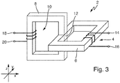
- Figure 3 shows the device 2 in a schematic three-dimensional view.
- the second magnetic circuit 8 is arranged at least in the area of the coupling section 12 essentially in a perpendicular plane of the first magnetic circuit 6 through the coupling section 12. This arrangement ensures that the magnetic field of the second magnetic circuit 8, in particular in the coupling region 12, is coupled essentially or mainly orthogonally to the alternating magnetic field in the first magnetic circuit 6.
- the first magnetic circuit 6 is aligned in an xy plane and the second magnetic circuit 8 is aligned in an xz plane.
- the arrangement according to the perpendicular plane includes, for example, any rotation or arrangement of the second magnetic circuit 8 in an xz plane.
- the arrangement of the second magnetic circuit 8 in the perpendicular plane of the first magnetic circuit 6 by the coupling section 12 includes any rotation of the FIG Figure 3 through the coupling area 12 and extending in the z-direction section of the second magnetic circuit 8 in the xz-plane.
- the other regions of the second magnetic circuit 8 that differ from the aforementioned section can, however, be oriented as desired, as long as the function of the second magnetic circuit 8 is maintained.
- one of the magnetic circuits 6 or 8 can also have an interruption, for example in the form of an air gap.
- one of the magnetic circuits 6 or 8 can also be equipped with a plunger core.
- multi-leg designs of the magnetic circuits 6 and 8 are also conceivable. It is therefore explicitly stated that the Figure 3 different designs are conceivable in order to carry out the methods explained in this description.
- Figure 4 shows in schematic form a further device 40 for compensating a ground fault.
- the device 40 comprises the one previously working according to the transducer principle Figures 1 to 3 explained device 2.
- the device 2 can be connected in parallel to further adjustable or non-adjustable inductances in order to provide a total inductance adapted to the case of an earth fault.
- a measuring element 42 is designed to determine a measured variable UNE which characterizes a potential earth fault and which represents a displacement voltage, the potential earth fault not yet having to be present when determining the measured variable UNE.
- the measured variable UNE is fed to a computing unit 44, which comprises a processor 46 and a memory element 48 connected to the processor 46.
- a computer program which is designed to carry out the method steps described here is stored on the memory element 48 to execute.
- measured variables determined such as the measured variable UNE, can be stored on the storage element 48.
- other or additional measured variables than the measured variable UNE can be evaluated in order to detect the potential earth fault.
- the phase currents and / or phase voltages of the field of the device 2 or other fields can be used to determine the potential earth fault.
- An operating parameter iSteuer (t) of the setting winding 10, which represents a potentially time-variant control current, is determined as a function of the at least one measured variable UNE by means of the arithmetic unit 44 in order to operate the compensation winding 4 at a ground fault operating point.
- other or additional measured variables can be evaluated than the measured variable UNE in order to determine the operating parameter iControl (t) by means of the arithmetic unit 44.
- the phase currents and / or phase voltages of the field of the device 2 or other fields can be used.
- the determination of the measured variable UNE and the determination of the operating parameter iSteuer (t) can be carried out both in a first and in a second operating mode, the first operating mode being characterized in that the medium or high voltage network 26 is in normal operation, with in normal operation there is no earth fault.
- the arithmetic unit 44 is designed to determine an earth fault in the medium or high voltage network 26, or the earth fault is determined in a further unit, not shown, and fed to the arithmetic unit 44. If the earth fault occurs now on, the device 40 changes to a second operating mode.
- the setting winding 10 is operated as a function of the at least one operating parameter iSteuer (t) in such a way that the compensation winding 4 is at the earth fault operating point.
- the operating parameter iControl (t) is fed to the current source 32, in particular to power electronics assigned to the current source 32.
- the operation of the compensation winding 4 in the earth fault operating point makes it possible to compensate for the capacitive current generated by an earth fault, for example, by the inductive current flowing in phase opposition by means of the compensation winding 4, and to minimize the harmonic currents.
- the ground fault operating point of the compensation winding 4 thus includes at least keeping the effective inductance constant in the event of a ground fault.
- the earth fault operating point can also include a variation over time of the inductance effective at the neutral point by means of the compensation winding 4. Consequently, the earth fault operating point is determined by the operating parameter iControl (t), which optionally includes an additional compensation signal for damping harmonics.
- Figure 5 shows a schematic flow diagram 50.
- the at least one measured variable UNE characterizing the potential earth fault is determined by means of the measuring element 42.
- the at least one operating parameter iSteuer (t) of the setting winding 10 is determined by means of the computing unit 44 as a function of the at least one measured variable UNE.
- the compensation signal is also determined, which, in addition to a starting point for the setting winding, provides a time-variant signal for compensating for harmonics.
- the case of an earth fault in the medium or high voltage network 26 is determined by means of the arithmetic unit 44.
- a step 58 when the earth fault is determined, the setting winding 10 is operated by means of the direct current source 32 as a function of the at least one operating parameter iSteuer (t), which includes the compensation signal, in such a way that the compensation winding 4 is in the earth fault operating point .
- variable currents can also be impressed on the setting winding with the direct current source 32. This is in part essential for the methods disclosed in this description. Reference is made here to the following explanations regarding the compensation signal.
- the direct current source 32 can also generate alternating currents, which is why it can generally also be referred to as a current source.
- Figure 6 shows a schematic state transition diagram 60.
- a third operating mode 66 is shown in the first operating mode 62.
- the medium or high voltage network 26 is in normal operation without a ground fault.
- the device 40 switches to the second operating mode 64 in order to compensate for the earth fault.
- an earth fault location is carried out, which is shown in FIG Figure 10 is explained in more detail. If the ground fault location can be carried out successfully in the third operating mode 66 and if, for example, the ground fault is successfully rectified due to the ground fault location, a change is made back to the first operating mode 62 in a rectification case 74.
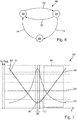
- Figure 7 shows a schematic displacement voltage-residual current detuning diagram 80.
- a profile 82 of an amount of an earth fault residual current IR and a profile 84 of the measured variable UNE in the form of the displacement voltage are plotted against a detuning V.
- the detuning V relates to a ratio between the basic oscillation reactive current component of the residual earth fault current IR and the capacitive current effective at the earth fault point. For a value of V equal to zero, there is ideal compensation for the earth fault. For V less than zero, the medium or high voltage network 26 is overcompensated. For V greater than 0, the medium or high voltage network 26 is undercompensated.
- I. R. I. wr 2 + I. L. - I. CE 2 + ⁇ v I. v 2 + I. u
- An active residual current IWR results from the ohmic losses in the event of a single-pole earth fault.
- the coil current IL is the inductive earth fault current and the capacitive earth fault current is marked ICE.
- the harmonic components of the earth fault current are marked with Iv.
- the operating parameter iControl (t) is determined in the first operating mode 62 in such a way that the compensation winding 4 can be operated at an earth fault operating point 90.
- the earth fault operating point 90 can in particular be referred to as the ideal operating point, since the earth fault residual current IR is minimal here.
- the term IL-ICE is minimized or tends towards zero at the earth fault operating point 90.
- the compensation winding 4 is operated, for example, at a normal operating point 91, so that the setting winding is in the de-energized state.
- An example is an operating range 86 of a plunger core coil according to the prior art and taking into account a maximum residual earth fault current IR shown.
- the plunger core coil automatically adjusts itself to a corresponding inductance, which effects compensation in the event of a ground fault. If an earth fault occurs, the inductance of the plunger coil is not changed based on normal operation. In addition, the ground fault operating point 90 cannot be reached in the first operating mode 62 with the plunger core coil according to the prior art.
- the inductance of the compensation winding 4 is briefly changed and the displacement voltage is evaluated in terms of the measured variable UNE.
- Operating point 90 is determined as a function of the displacement voltage. Of course, other measured variables can also be used to determine the earth fault operating point 90.
- a first threshold 92 for the displacement voltage must not be exceeded permanently.
- a second threshold 94 also not being allowed to be exceeded briefly. This results in a range 96 of detuning V around V equal to zero, in which the high-voltage network 26 may not be operated even for a short time in its normal operation. This means, in particular for a plunger core coil, that it must not be operated at operating point 90 due to its essentially fixed or non-dynamically changeable inductance.
- the device 40 allows the high-voltage network 26 to be operated without current in the first operating mode 62 and then, in the event of an earth fault, to approach the previously determined earth fault operating point 90 by energizing the setting winding 10 and at operating point 90 by means of a time-variant operating parameter for the setting winding 10 To dampen harmonics.
- the approach to the ground fault operating point 90 can of course also be transferred to the case of a medium-voltage network 26.
- Figure 8 shows a schematic voltage-inductance-time diagram 100.
- the measured variable UNE is at a first level U1 according to a curve 102, to a second level at a point in time tV due to a change in the medium or high voltage network 26 Voltage level U2 to drop.
- a change in the medium-voltage or high-voltage network is therefore determined at the point in time tV in the first operating mode 62.
- a first inductance L1 is specified for the compensation winding 4 according to a curve 104 and the device 40 is operated accordingly.
- the setting winding 10 can also be de-energized. It goes without saying, however, that the setting winding 10 can also be supplied with current in order to achieve the inductance L1.
- a second inductance L2 is determined for the case of an earth fault 68 as a function of the measured variable UNE or as a function of a further measured variable. If the aforementioned change is determined at the point in time tV, a third inductance L3 for the event of an earth fault is determined in a period T2 following the first period T1. In the second time period T2, the compensation winding 4 dwells at the first inductance L1.
- the ground fault case 68 is determined at a point in time tES and the device 40 is operated in such a way that, in the second operating mode 64, the compensation winding 4 is set to the third inductance L3 according to the curve 104.
- the earth fault is therefore compensated for in a third time period T3.
- the change in the inductance L1 of the compensation winding 4 towards the inductance L3 is part of a change in the operating point at the point in time tES.
- the inductance L3 can be changed over time in the time period T3 in order to dampen harmonics, for example.
- Figure 9 shows in one embodiment the medium or high voltage network 26, the device 40 being represented schematically by means of the device 2, the computing unit 44 and the measuring element 42.
- Branches A, B and C are shown in which the respective currents I and voltages U are measured and made available to the arithmetic unit 44.
- the arithmetic unit 44 determines one or more harmonics of the earth fault current from the supplied variables, the harmonics according to FIG Equation 1 can be represented by the term ⁇ v I v 2 .
- the arithmetic unit 44 determines a compensation signal in phase opposition to the respective harmonic in the sense of a further operating parameter.
- a number of anti-phase compensation signals is determined according to the number of detected harmonics.
- a respective one of the anti-phase compensation signals comprises a corresponding frequency in the sense of a multiple of the network frequency, an amplitude and a phase.
- the anti-phase compensation signal is understood to be a signal which, introduced into the medium or high voltage network via the corresponding operation of the setting winding 10, has an anti-phase effect on the harmonic to be reduced.
- the frequencies and phases of the compensation signal and the harmonic to be reduced can differ.
- the anti-phase compensation signals are converted into a corresponding current signal and can thus be added to the operating parameter iControl (t) that has already been determined.
- the arithmetic unit 44 thus operates the setting winding 10 by means of the direct current source 32 as a function of the at least one operating parameter UNE and the compensation signal in such a way that the compensation winding 4 reduces an amplitude of the harmonic of the fault current at the earth fault operating point 90.
- the ground fault operating point 90 thus includes a setting of a time-variant inductance of the compensation winding 4, this inductance Includes frequency components with a multiple of the network frequency of the medium or high voltage network 26.
- the compensation winding 4 can also be determined as a function of the network variables Ua to Uc and / or Ia to Ic without taking the operating parameter UNE into account.
- the function 1 / L is selected in such a way that individual harmonics can be specifically generated in the sense of amplitude modulation. If, for example, a cosine-shaped curve is selected, a combination of individual frequency components according to equation 3 can be specifically generated according to the addition theorem.
- a modulation function according to equation 4 results, taking into account a stationary inductance L1, ie for a fundamental component.
- L. 1 L. 1 + A. 4th ⁇ cos 4th ⁇ t - ⁇ 4th
- the control current iControl (t) comprises a direct current component iDC and the compensation signal for operating the setting winding 10 and results from equation 5.
- the compensation signal is shown on the right-hand side of the direct current component iDC.
- Figure 10 shows in schematic form an earth fault location method which is carried out by means of the device 40.
- the operating parameter iControl (t) is varied in such a way that a pulse pattern 110 is formed in the medium or high voltage network 26. In Figure 7 this would correspond to a periodic deviation from the ideal earth fault operating point 90, at which the residual current IR is minimized, and a short-term setting of a pulse operating point 112.
- the setting winding 10 is controlled by means of a corresponding time-variant operating parameter iControl (t) operated in such a way that a periodic change takes place between the earth fault operating point 90 and the pulse operating point 112.
- a corresponding measuring point 114a, 114b and 114c is located at each of the branches 116a, 116b and 116c.
- branch 116c it is established at measuring point 114c that the sum of all phase currents is not constant due to the pronounced pulse pattern 110, whereby branch 116c includes the earth fault.
- the measuring point 114c is transmitted this deviation, for example, to the device 4 or a higher-level reporting point, with which fault location and reporting is carried out.
- FIG 11 shows a schematic view of the device 2 in an alternative embodiment.
- Second magnetic circuits 8 run within the first magnetic circuit 6 through respective coupling sections 12.
- the second magnetic circuits 8 are generated with the aid of setting windings 10 passed through a core material 110 of the first magnetic circuit 8 and cause a virtual, adjustable air gap in relation to the first magnetic one Circuit 6.
- the core material 110, together with the magnetic circuit 6, is part of the inductance 4, so there is only one iron core.
- the inductance of the compensation winding 4 can thus be adjusted by means of the setting winding 10 of a respective magnetic circuit.
Landscapes
- Physics & Mathematics (AREA)
- General Physics & Mathematics (AREA)
- Testing Of Short-Circuits, Discontinuities, Leakage, Or Incorrect Line Connections (AREA)
- Emergency Protection Circuit Devices (AREA)
Priority Applications (1)
| Application Number | Priority Date | Filing Date | Title |
|---|---|---|---|
| PL17174328T PL3287796T3 (pl) | 2016-06-06 | 2017-06-02 | Sposób i urządzenie do kompensacji zwarcia doziemnego |
Applications Claiming Priority (1)
| Application Number | Priority Date | Filing Date | Title |
|---|---|---|---|
| DE102016110420.5A DE102016110420A1 (de) | 2016-06-06 | 2016-06-06 | Verfahren und Vorrichtung zur Kompensation eines Erdschlusses |
Publications (3)
| Publication Number | Publication Date |
|---|---|
| EP3287796A2 EP3287796A2 (de) | 2018-02-28 |
| EP3287796A3 EP3287796A3 (de) | 2018-06-20 |
| EP3287796B1 true EP3287796B1 (de) | 2021-03-03 |
Family
ID=59030797
Family Applications (1)
| Application Number | Title | Priority Date | Filing Date |
|---|---|---|---|
| EP17174328.9A Active EP3287796B1 (de) | 2016-06-06 | 2017-06-02 | Verfahren und vorrichtung zur kompensation eines erdschlusses |
Country Status (3)
| Country | Link |
|---|---|
| EP (1) | EP3287796B1 (pl) |
| DE (1) | DE102016110420A1 (pl) |
| PL (1) | PL3287796T3 (pl) |
Families Citing this family (3)
| Publication number | Priority date | Publication date | Assignee | Title |
|---|---|---|---|---|
| FI130596B (en) | 2019-02-04 | 2023-11-30 | Ensto Oy | Apparatus and procedure for using an electrical network |
| EP3907840A1 (de) * | 2020-05-08 | 2021-11-10 | Siemens Aktiengesellschaft | Verfahren und vorrichtung zur kompensation einer auf einem dreiphasigen spannungsversorgungsnetz auftretenden leitungsstörung |
| US11411389B1 (en) * | 2021-03-15 | 2022-08-09 | General Electric Technology Gmbh | Systems and methods for a controlled dynamic MHO distance characteristic |
Family Cites Families (11)
| Publication number | Priority date | Publication date | Assignee | Title |
|---|---|---|---|---|
| DE702814C (de) | 1938-08-02 | 1941-02-17 | Bbc Brown Boveri & Cie | Regelbare Loeschinduktivitaet fuer den induktiven |
| DE2711629C2 (de) * | 1977-03-17 | 1978-12-07 | Gossen Gmbh, 8520 Erlangen | Verfahren und Schaltungsanordnung zum Orten von Dauererdschlüssen in Drehstromnetzen |
| DE4413649C2 (de) * | 1994-04-20 | 1998-07-16 | Eberle A Gmbh | Meßverfahren und Schaltungsanordnung zur Ortung von Dauererdschlüssen |
| DE4429310C2 (de) * | 1994-08-18 | 1998-01-15 | Eberle A Gmbh | Verfahren und Vorrichtung zur Ortung von Erdschlüssen in Drehstromnetzen |
| DE19525417C2 (de) * | 1995-07-12 | 2000-03-23 | Starkstrom Geraetebau Gmbh | Anordnung zur Erdschluß-Stromkompensation eines mehrphasigen elektrischen Leitungsnetzes |
| AT411937B (de) * | 2000-08-11 | 2004-07-26 | Adaptive Regelsysteme Ges M B | Verfahren und vorrichtung zur erkennung und ortung von hochohmigen einpoligen erdfehlern |
| DE10146294C1 (de) * | 2001-09-19 | 2003-07-17 | Edc Gmbh | Abstimmung einer Erdschlusslöschspule auch während des Erdschlusses |
| DE10215025A1 (de) * | 2002-04-03 | 2003-10-16 | Kries Energietechnik Gmbh & Co | Verfahren und Vorrichtung zur Erkennung und/oder Ortung von Erdschlüssen und Kurzschlüssen in Drehstromnetzen |
| DE102007017543B4 (de) * | 2006-04-10 | 2012-12-13 | Technische Universität Graz | Verfahren zur Entfernungsortung von Erdschlüssen |
| AT509837B1 (de) * | 2010-02-25 | 2013-06-15 | Oebb Infrastruktur Ag | Vorrichtung zur fehlerstromreduktion |
| CZ308721B6 (cs) * | 2014-08-28 | 2021-03-24 | Ege, Spol.S R.O. | Způsob a zařízení pro automatické nastavení plynule a/nebo diskrétně laditelné zhášecí tlumivky v kompenzované síti elektrické soustavy |
-
2016
- 2016-06-06 DE DE102016110420.5A patent/DE102016110420A1/de not_active Withdrawn
-
2017
- 2017-06-02 PL PL17174328T patent/PL3287796T3/pl unknown
- 2017-06-02 EP EP17174328.9A patent/EP3287796B1/de active Active
Non-Patent Citations (1)
| Title |
|---|
| None * |
Also Published As
| Publication number | Publication date |
|---|---|
| DE102016110420A1 (de) | 2017-12-07 |
| EP3287796A3 (de) | 2018-06-20 |
| PL3287796T3 (pl) | 2021-09-13 |
| EP3287796A2 (de) | 2018-02-28 |
Similar Documents
| Publication | Publication Date | Title |
|---|---|---|
| EP2622615B1 (de) | Anordnung und verfahren zur kompensation eines magnetischen gleichflusses in einem transformatorkern | |
| DE69332697T2 (de) | Verfahren und Vorrichtung zur Feststellung eines Erdschlusswiderstandes in einem Elektrofahrzeug | |
| DE19930412C1 (de) | Aktiv abgeschirmte supraleitende Magnetanordnung mit Feldstörungskompensation | |
| DE102007049667B4 (de) | Anordnung und Verfahren zur Kompensation eines Fehlerstromes bei einem Erdschluss | |
| EP3663783B1 (de) | Magnetfeld-messvorrichtung und verfahren zur erfassung eines lokalisierungsstroms in einem verzweigten wechselstrom-stromversorgungssystem | |
| DE3208133A1 (de) | Elektromagnetisches lager mit redundanzeigenschaften | |
| EP1065513B1 (de) | Aktiv abgeschirmte supraleitende Magnetanordnung mit Feldstörungskompensation | |
| DE19532149A1 (de) | Verfahren und Vorrichtung zur Korrektur einer Flußrichtung eines Modellflusses einer geberlosen, feldorientiert betriebenen Drehfeldmaschine bis zur Frequenz Null | |
| EP3287796B1 (de) | Verfahren und vorrichtung zur kompensation eines erdschlusses | |
| DE112015003484B4 (de) | Energie-Umwandlungsvorrichtung | |
| EP1182463B1 (de) | Dimensionierung zusätzlicher Strompfade zur Optimierung des Störverhaltens einer supraleitenden Magnetanordnung | |
| DE10241966A1 (de) | Supraleitende Magnetanordnung und Verfahren | |
| DE69329326T2 (de) | Verfahren und Vorrichtung zum Messen der Anpassung und Fehlanpassung der Kompensation eines Stromversorgungsnetzes | |
| EP4409311B1 (de) | Indirektes kalibrierverfahren für ein elektromagnetisches induktionsverfahren und messanordnung zur durchführung des verfahrens | |
| DE2731453C3 (de) | Erdschlußdetektor | |
| EP2362514B1 (de) | Vorrichtung zur Fehlerstromreduktion | |
| DE102008037831B4 (de) | Verfahren zum Betreiben eines Fehlerstromschutzschalters sowie Fehlerstromschutzschalter | |
| EP1182462B1 (de) | Dimensionierung einer Magnetanordnung mit einem zusätzlichen stromführenden Spulensystem | |
| DE2103340B2 (de) | Verfahren und Vorrichtung zur Fein stabilisierung der magnetischen Feld starke eines Kernresonanzspektrometers | |
| DE69114479T2 (de) | Lagedetektor. | |
| EP2169797B1 (de) | Verfahren und messvorrichtung zur messung eines ausgangsstroms einer getakteten halbbrueckenschaltung | |
| AT524958B1 (de) | Verfahren zur Ermittlung von Netzparametern zur Regelung einer Petersen-Spule | |
| DE1463139A1 (de) | Anzeigevorrichtung fuer einen Belastungszustand eines Stromkreises | |
| DE968624C (de) | Schutzeinrichtung in Mehrphasennetzen mit Kurzschlussfortschaltung | |
| EP2428773B1 (de) | Phasenanaloger Wegsensor |
Legal Events
| Date | Code | Title | Description |
|---|---|---|---|
| PUAI | Public reference made under article 153(3) epc to a published international application that has entered the european phase |
Free format text: ORIGINAL CODE: 0009012 |
|
| STAA | Information on the status of an ep patent application or granted ep patent |
Free format text: STATUS: THE APPLICATION HAS BEEN PUBLISHED |
|
| AK | Designated contracting states |
Kind code of ref document: A2 Designated state(s): AL AT BE BG CH CY CZ DE DK EE ES FI FR GB GR HR HU IE IS IT LI LT LU LV MC MK MT NL NO PL PT RO RS SE SI SK SM TR |
|
| AX | Request for extension of the european patent |
Extension state: BA ME |
|
| PUAL | Search report despatched |
Free format text: ORIGINAL CODE: 0009013 |
|
| AK | Designated contracting states |
Kind code of ref document: A3 Designated state(s): AL AT BE BG CH CY CZ DE DK EE ES FI FR GB GR HR HU IE IS IT LI LT LU LV MC MK MT NL NO PL PT RO RS SE SI SK SM TR |
|
| AX | Request for extension of the european patent |
Extension state: BA ME |
|
| RIC1 | Information provided on ipc code assigned before grant |
Ipc: G01R 31/11 20060101ALI20180516BHEP Ipc: H01F 29/14 20060101ALI20180516BHEP Ipc: H02H 7/26 20060101ALI20180516BHEP Ipc: G01R 31/08 20060101ALI20180516BHEP Ipc: G01R 31/02 20060101AFI20180516BHEP Ipc: H02H 9/08 20060101ALI20180516BHEP |
|
| STAA | Information on the status of an ep patent application or granted ep patent |
Free format text: STATUS: REQUEST FOR EXAMINATION WAS MADE |
|
| 17P | Request for examination filed |
Effective date: 20181022 |
|
| RBV | Designated contracting states (corrected) |
Designated state(s): AL AT BE BG CH CY CZ DE DK EE ES FI FR GB GR HR HU IE IS IT LI LT LU LV MC MK MT NL NO PL PT RO RS SE SI SK SM TR |
|
| STAA | Information on the status of an ep patent application or granted ep patent |
Free format text: STATUS: EXAMINATION IS IN PROGRESS |
|
| 17Q | First examination report despatched |
Effective date: 20200416 |
|
| REG | Reference to a national code |
Ref country code: DE Ref legal event code: R079 Ref document number: 502017009541 Country of ref document: DE Free format text: PREVIOUS MAIN CLASS: G01R0031020000 Ipc: G01R0031520000 |
|
| GRAP | Despatch of communication of intention to grant a patent |
Free format text: ORIGINAL CODE: EPIDOSNIGR1 |
|
| STAA | Information on the status of an ep patent application or granted ep patent |
Free format text: STATUS: GRANT OF PATENT IS INTENDED |
|
| RIC1 | Information provided on ipc code assigned before grant |
Ipc: H02H 7/26 20060101ALI20201019BHEP Ipc: H02H 9/08 20060101ALI20201019BHEP Ipc: G01R 31/08 20200101ALI20201019BHEP Ipc: H01F 29/14 20060101ALI20201019BHEP Ipc: G01R 31/52 20200101AFI20201019BHEP Ipc: G01R 31/11 20060101ALI20201019BHEP |
|
| INTG | Intention to grant announced |
Effective date: 20201103 |
|
| GRAS | Grant fee paid |
Free format text: ORIGINAL CODE: EPIDOSNIGR3 |
|
| GRAA | (expected) grant |
Free format text: ORIGINAL CODE: 0009210 |
|
| STAA | Information on the status of an ep patent application or granted ep patent |
Free format text: STATUS: THE PATENT HAS BEEN GRANTED |
|
| AK | Designated contracting states |
Kind code of ref document: B1 Designated state(s): AL AT BE BG CH CY CZ DE DK EE ES FI FR GB GR HR HU IE IS IT LI LT LU LV MC MK MT NL NO PL PT RO RS SE SI SK SM TR |
|
| REG | Reference to a national code |
Ref country code: GB Ref legal event code: FG4D Free format text: NOT ENGLISH |
|
| REG | Reference to a national code |
Ref country code: AT Ref legal event code: REF Ref document number: 1367793 Country of ref document: AT Kind code of ref document: T Effective date: 20210315 Ref country code: CH Ref legal event code: EP |
|
| REG | Reference to a national code |
Ref country code: DE Ref legal event code: R096 Ref document number: 502017009541 Country of ref document: DE |
|
| REG | Reference to a national code |
Ref country code: CH Ref legal event code: NV Representative=s name: DREISS PATENTANWAELTE PARTG MBB, DE Ref country code: IE Ref legal event code: FG4D Free format text: LANGUAGE OF EP DOCUMENT: GERMAN |
|
| REG | Reference to a national code |
Ref country code: LT Ref legal event code: MG9D |
|
| PG25 | Lapsed in a contracting state [announced via postgrant information from national office to epo] |
Ref country code: FI Free format text: LAPSE BECAUSE OF FAILURE TO SUBMIT A TRANSLATION OF THE DESCRIPTION OR TO PAY THE FEE WITHIN THE PRESCRIBED TIME-LIMIT Effective date: 20210303 Ref country code: HR Free format text: LAPSE BECAUSE OF FAILURE TO SUBMIT A TRANSLATION OF THE DESCRIPTION OR TO PAY THE FEE WITHIN THE PRESCRIBED TIME-LIMIT Effective date: 20210303 Ref country code: GR Free format text: LAPSE BECAUSE OF FAILURE TO SUBMIT A TRANSLATION OF THE DESCRIPTION OR TO PAY THE FEE WITHIN THE PRESCRIBED TIME-LIMIT Effective date: 20210604 Ref country code: NO Free format text: LAPSE BECAUSE OF FAILURE TO SUBMIT A TRANSLATION OF THE DESCRIPTION OR TO PAY THE FEE WITHIN THE PRESCRIBED TIME-LIMIT Effective date: 20210603 Ref country code: BG Free format text: LAPSE BECAUSE OF FAILURE TO SUBMIT A TRANSLATION OF THE DESCRIPTION OR TO PAY THE FEE WITHIN THE PRESCRIBED TIME-LIMIT Effective date: 20210603 Ref country code: LT Free format text: LAPSE BECAUSE OF FAILURE TO SUBMIT A TRANSLATION OF THE DESCRIPTION OR TO PAY THE FEE WITHIN THE PRESCRIBED TIME-LIMIT Effective date: 20210303 |
|
| REG | Reference to a national code |
Ref country code: NL Ref legal event code: MP Effective date: 20210303 |
|
| PG25 | Lapsed in a contracting state [announced via postgrant information from national office to epo] |
Ref country code: LV Free format text: LAPSE BECAUSE OF FAILURE TO SUBMIT A TRANSLATION OF THE DESCRIPTION OR TO PAY THE FEE WITHIN THE PRESCRIBED TIME-LIMIT Effective date: 20210303 Ref country code: RS Free format text: LAPSE BECAUSE OF FAILURE TO SUBMIT A TRANSLATION OF THE DESCRIPTION OR TO PAY THE FEE WITHIN THE PRESCRIBED TIME-LIMIT Effective date: 20210303 Ref country code: SE Free format text: LAPSE BECAUSE OF FAILURE TO SUBMIT A TRANSLATION OF THE DESCRIPTION OR TO PAY THE FEE WITHIN THE PRESCRIBED TIME-LIMIT Effective date: 20210303 |
|
| PG25 | Lapsed in a contracting state [announced via postgrant information from national office to epo] |
Ref country code: NL Free format text: LAPSE BECAUSE OF FAILURE TO SUBMIT A TRANSLATION OF THE DESCRIPTION OR TO PAY THE FEE WITHIN THE PRESCRIBED TIME-LIMIT Effective date: 20210303 |
|
| PG25 | Lapsed in a contracting state [announced via postgrant information from national office to epo] |
Ref country code: SM Free format text: LAPSE BECAUSE OF FAILURE TO SUBMIT A TRANSLATION OF THE DESCRIPTION OR TO PAY THE FEE WITHIN THE PRESCRIBED TIME-LIMIT Effective date: 20210303 Ref country code: EE Free format text: LAPSE BECAUSE OF FAILURE TO SUBMIT A TRANSLATION OF THE DESCRIPTION OR TO PAY THE FEE WITHIN THE PRESCRIBED TIME-LIMIT Effective date: 20210303 |
|
| PG25 | Lapsed in a contracting state [announced via postgrant information from national office to epo] |
Ref country code: PT Free format text: LAPSE BECAUSE OF FAILURE TO SUBMIT A TRANSLATION OF THE DESCRIPTION OR TO PAY THE FEE WITHIN THE PRESCRIBED TIME-LIMIT Effective date: 20210705 Ref country code: RO Free format text: LAPSE BECAUSE OF FAILURE TO SUBMIT A TRANSLATION OF THE DESCRIPTION OR TO PAY THE FEE WITHIN THE PRESCRIBED TIME-LIMIT Effective date: 20210303 Ref country code: SK Free format text: LAPSE BECAUSE OF FAILURE TO SUBMIT A TRANSLATION OF THE DESCRIPTION OR TO PAY THE FEE WITHIN THE PRESCRIBED TIME-LIMIT Effective date: 20210303 Ref country code: IS Free format text: LAPSE BECAUSE OF FAILURE TO SUBMIT A TRANSLATION OF THE DESCRIPTION OR TO PAY THE FEE WITHIN THE PRESCRIBED TIME-LIMIT Effective date: 20210703 |
|
| REG | Reference to a national code |
Ref country code: DE Ref legal event code: R097 Ref document number: 502017009541 Country of ref document: DE |
|
| PLBE | No opposition filed within time limit |
Free format text: ORIGINAL CODE: 0009261 |
|
| STAA | Information on the status of an ep patent application or granted ep patent |
Free format text: STATUS: NO OPPOSITION FILED WITHIN TIME LIMIT |
|
| PG25 | Lapsed in a contracting state [announced via postgrant information from national office to epo] |
Ref country code: MC Free format text: LAPSE BECAUSE OF FAILURE TO SUBMIT A TRANSLATION OF THE DESCRIPTION OR TO PAY THE FEE WITHIN THE PRESCRIBED TIME-LIMIT Effective date: 20210303 Ref country code: DK Free format text: LAPSE BECAUSE OF FAILURE TO SUBMIT A TRANSLATION OF THE DESCRIPTION OR TO PAY THE FEE WITHIN THE PRESCRIBED TIME-LIMIT Effective date: 20210303 Ref country code: AL Free format text: LAPSE BECAUSE OF FAILURE TO SUBMIT A TRANSLATION OF THE DESCRIPTION OR TO PAY THE FEE WITHIN THE PRESCRIBED TIME-LIMIT Effective date: 20210303 Ref country code: ES Free format text: LAPSE BECAUSE OF FAILURE TO SUBMIT A TRANSLATION OF THE DESCRIPTION OR TO PAY THE FEE WITHIN THE PRESCRIBED TIME-LIMIT Effective date: 20210303 |
|
| 26N | No opposition filed |
Effective date: 20211206 |
|
| GBPC | Gb: european patent ceased through non-payment of renewal fee |
Effective date: 20210603 |
|
| PG25 | Lapsed in a contracting state [announced via postgrant information from national office to epo] |
Ref country code: SI Free format text: LAPSE BECAUSE OF FAILURE TO SUBMIT A TRANSLATION OF THE DESCRIPTION OR TO PAY THE FEE WITHIN THE PRESCRIBED TIME-LIMIT Effective date: 20210303 |
|
| REG | Reference to a national code |
Ref country code: BE Ref legal event code: MM Effective date: 20210630 |
|
| PG25 | Lapsed in a contracting state [announced via postgrant information from national office to epo] |
Ref country code: LU Free format text: LAPSE BECAUSE OF NON-PAYMENT OF DUE FEES Effective date: 20210602 |
|
| PG25 | Lapsed in a contracting state [announced via postgrant information from national office to epo] |
Ref country code: IT Free format text: LAPSE BECAUSE OF FAILURE TO SUBMIT A TRANSLATION OF THE DESCRIPTION OR TO PAY THE FEE WITHIN THE PRESCRIBED TIME-LIMIT Effective date: 20210303 Ref country code: IE Free format text: LAPSE BECAUSE OF NON-PAYMENT OF DUE FEES Effective date: 20210602 Ref country code: GB Free format text: LAPSE BECAUSE OF NON-PAYMENT OF DUE FEES Effective date: 20210603 |
|
| PG25 | Lapsed in a contracting state [announced via postgrant information from national office to epo] |
Ref country code: IS Free format text: LAPSE BECAUSE OF FAILURE TO SUBMIT A TRANSLATION OF THE DESCRIPTION OR TO PAY THE FEE WITHIN THE PRESCRIBED TIME-LIMIT Effective date: 20210703 Ref country code: FR Free format text: LAPSE BECAUSE OF NON-PAYMENT OF DUE FEES Effective date: 20210630 |
|
| PG25 | Lapsed in a contracting state [announced via postgrant information from national office to epo] |
Ref country code: BE Free format text: LAPSE BECAUSE OF NON-PAYMENT OF DUE FEES Effective date: 20210630 |
|
| PG25 | Lapsed in a contracting state [announced via postgrant information from national office to epo] |
Ref country code: HU Free format text: LAPSE BECAUSE OF FAILURE TO SUBMIT A TRANSLATION OF THE DESCRIPTION OR TO PAY THE FEE WITHIN THE PRESCRIBED TIME-LIMIT; INVALID AB INITIO Effective date: 20170602 |
|
| PG25 | Lapsed in a contracting state [announced via postgrant information from national office to epo] |
Ref country code: CY Free format text: LAPSE BECAUSE OF FAILURE TO SUBMIT A TRANSLATION OF THE DESCRIPTION OR TO PAY THE FEE WITHIN THE PRESCRIBED TIME-LIMIT Effective date: 20210303 |
|
| P01 | Opt-out of the competence of the unified patent court (upc) registered |
Effective date: 20230809 |
|
| PG25 | Lapsed in a contracting state [announced via postgrant information from national office to epo] |
Ref country code: MK Free format text: LAPSE BECAUSE OF FAILURE TO SUBMIT A TRANSLATION OF THE DESCRIPTION OR TO PAY THE FEE WITHIN THE PRESCRIBED TIME-LIMIT Effective date: 20210303 |
|
| PG25 | Lapsed in a contracting state [announced via postgrant information from national office to epo] |
Ref country code: TR Free format text: LAPSE BECAUSE OF FAILURE TO SUBMIT A TRANSLATION OF THE DESCRIPTION OR TO PAY THE FEE WITHIN THE PRESCRIBED TIME-LIMIT Effective date: 20210303 |
|
| PG25 | Lapsed in a contracting state [announced via postgrant information from national office to epo] |
Ref country code: MT Free format text: LAPSE BECAUSE OF FAILURE TO SUBMIT A TRANSLATION OF THE DESCRIPTION OR TO PAY THE FEE WITHIN THE PRESCRIBED TIME-LIMIT Effective date: 20210303 |
|
| PGFP | Annual fee paid to national office [announced via postgrant information from national office to epo] |
Ref country code: PL Payment date: 20250522 Year of fee payment: 9 |
|
| PGFP | Annual fee paid to national office [announced via postgrant information from national office to epo] |
Ref country code: AT Payment date: 20250623 Year of fee payment: 9 |
|
| PGFP | Annual fee paid to national office [announced via postgrant information from national office to epo] |
Ref country code: CZ Payment date: 20250527 Year of fee payment: 9 |
|
| PGFP | Annual fee paid to national office [announced via postgrant information from national office to epo] |
Ref country code: DE Payment date: 20250815 Year of fee payment: 9 |
|
| PGFP | Annual fee paid to national office [announced via postgrant information from national office to epo] |
Ref country code: CH Payment date: 20250701 Year of fee payment: 9 |