EP3288675B1 - Chargement de matière particulaire dans des tubes verticaux - Google Patents
Chargement de matière particulaire dans des tubes verticaux Download PDFInfo
- Publication number
- EP3288675B1 EP3288675B1 EP16787247.2A EP16787247A EP3288675B1 EP 3288675 B1 EP3288675 B1 EP 3288675B1 EP 16787247 A EP16787247 A EP 16787247A EP 3288675 B1 EP3288675 B1 EP 3288675B1
- Authority
- EP
- European Patent Office
- Prior art keywords
- hub
- columnar body
- yielding lines
- free
- yielding
- Prior art date
- Legal status (The legal status is an assumption and is not a legal conclusion. Google has not performed a legal analysis and makes no representation as to the accuracy of the status listed.)
- Active
Links
Images


Classifications
-
- B—PERFORMING OPERATIONS; TRANSPORTING
- B01—PHYSICAL OR CHEMICAL PROCESSES OR APPARATUS IN GENERAL
- B01J—CHEMICAL OR PHYSICAL PROCESSES, e.g. CATALYSIS OR COLLOID CHEMISTRY; THEIR RELEVANT APPARATUS
- B01J8/00—Chemical or physical processes in general, conducted in the presence of fluids and solid particles; Apparatus for such processes
- B01J8/02—Chemical or physical processes in general, conducted in the presence of fluids and solid particles; Apparatus for such processes with stationary particles, e.g. in fixed beds
- B01J8/06—Chemical or physical processes in general, conducted in the presence of fluids and solid particles; Apparatus for such processes with stationary particles, e.g. in fixed beds in tube reactors; the solid particles being arranged in tubes
-
- B—PERFORMING OPERATIONS; TRANSPORTING
- B01—PHYSICAL OR CHEMICAL PROCESSES OR APPARATUS IN GENERAL
- B01J—CHEMICAL OR PHYSICAL PROCESSES, e.g. CATALYSIS OR COLLOID CHEMISTRY; THEIR RELEVANT APPARATUS
- B01J8/00—Chemical or physical processes in general, conducted in the presence of fluids and solid particles; Apparatus for such processes
- B01J8/0015—Feeding of the particles in the reactor; Evacuation of the particles out of the reactor
- B01J8/002—Feeding of the particles in the reactor; Evacuation of the particles out of the reactor with a moving instrument
-
- B—PERFORMING OPERATIONS; TRANSPORTING
- B01—PHYSICAL OR CHEMICAL PROCESSES OR APPARATUS IN GENERAL
- B01J—CHEMICAL OR PHYSICAL PROCESSES, e.g. CATALYSIS OR COLLOID CHEMISTRY; THEIR RELEVANT APPARATUS
- B01J8/00—Chemical or physical processes in general, conducted in the presence of fluids and solid particles; Apparatus for such processes
- B01J8/0015—Feeding of the particles in the reactor; Evacuation of the particles out of the reactor
- B01J8/003—Feeding of the particles in the reactor; Evacuation of the particles out of the reactor in a downward flow
-
- B—PERFORMING OPERATIONS; TRANSPORTING
- B01—PHYSICAL OR CHEMICAL PROCESSES OR APPARATUS IN GENERAL
- B01J—CHEMICAL OR PHYSICAL PROCESSES, e.g. CATALYSIS OR COLLOID CHEMISTRY; THEIR RELEVANT APPARATUS
- B01J2208/00—Processes carried out in the presence of solid particles; Reactors therefor
- B01J2208/00743—Feeding or discharging of solids
- B01J2208/00752—Feeding
Definitions
- the exemplary embodiments relate to techniques and apparatus for loading particulate material such as, for example, catalyst into vertical tubes such as, for example, in a catalyst reactor.
- the invention provides an apparatus for dampening and uniformly loading a particulate catalyst material inside a vertical reactor tube in accordance with Claim 1.
- the invention further provides a method for filling a particulate catalyst material into a reactor tube in accordance with Claim 14.
- the exemplary embodiments relate to dampening and uniform loading devices and methods for loading a particulate material inside a vertical tube and include a columnar body having a longitudinal axis aligned in a vertical direction and a plurality of yielding lines. Each respect yield line is fixed at a first end and at a second end to the columnar body, and has a free-standing portion between the first end and the second end. The free-standing portion is configured to spiral around the columnar body.
- radial or “radially” include directions outward toward the inner wall of a tube (such as a tube in a catalyst reactor) but are not limited to directions perpendicular to an axial direction of the tube. Rather such directions, although including perpendicular and outward toward the inner wall of the tube, also include those transverse and/or off center yet moving outward or even against the surface of the inner wall of the tube.
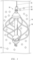
- Figure 1 depicts a dampening and uniform loading device 10 which may be used to load particulate material (such as catalyst) 12 into a tube 14.
- One or more dampening and uniform loading devices 10 are generally mounted on feed line 16 and may include rotating connectors 18 as taught by McNaughton in US Patent No. 7,673,660 .
- the tube 14 may have various regions of dis-uniformity such as, for example, regions of tube weld and weld impingement 15, bends in the tube (not shown), etc.
- the feed line 16 is used to lower ⁇ e.g. slow controlled descent) the dampening and uniform loading devices) 10 into the tube 14 and to raise the dampening and uniform loading devices) 10 out of the tube 14 as the tube 14 is being filled.
- the dampening and uniform loading devices) 10 may be lowered and raised from the tube 14 by any known means or technique.
- the dampening and uniform loading devices) 10 may be connected to the feed line 16 via the rotating connector 18 (or any other known means for rotating the dampening and uniform loading devices 10).
- the rotating connector 18 may be connected at any desirable point along the feed line 16 and as shown is connected at the lower end.
- the rotating connector 18 may for example be a stainless steel rotating or rotational device such as known to one of ordinary skill in the art.
- Stainless steel chain links 17 may be used to join the rotating connector 18 to the feed line 16, or the rotating connector 18 to the dampening and uniform loading device 10.
- the rotating connector 18 allows the dampening and uniform loading devices) 10 to rotate without twisting the feed line 16 during a particulate material (such as catalyst) 12 loading or filling operation.
- the dampening and uniform loading devices 10 generally have a columnar body 20 and a plurality of yield lines 60.
- Each of the plurality of yield lines 60 has a first end 62a and a second end 62b that are fixed to the columnar body 20. Once the ends 62a, 62b are fixed, each of the plurality of yield lines 60 also has a free-standing portion 64 between the first end 62a and the second end 62b. Such free-standing portion(s) 64 spiral around and spaced away from the columnar body 20.
- the columnar body 20 generally has a rod 22, first and second hubs 30a, 30b, and glancing impingement device(s) 50.
- the rod 22 and accordingly the columnar body 20 have a longitudinal axis aligned in a vertical direction when the dampening and uniform loading device(s) 10 is in the tube 14.
- the rod 22 has holes 24 horizontally through the rod 22.
- the rod 22 has many holes 24 allowing for user selection of a desired height or position for attachment of the first and second hubs 30a, 30b.
- the rod 22 has means of attachment such as an opening 26 through a narrowed tip 28 for connecting the rod 22 in an exemplary embodiment to stainless steel chain links 17, to the rotating connector 18, and/or to the feed line 16.
- the first hub 30a is mounted on and attached proximate one end of the rod 22 via a bolt 36 and a nut 37 (or other known means of attachment) through a hole 24.
- the second hub 30b is mounted over and attached proximate the other end of the rod 22 via a bolt 36 and a nut 37 (or other known means of attachment) through a hole 24.
- the first end 62a of each of said plurality of yielding lines 60 may be fixed to the first hub 30a.
- the second end 62b of each of said plurality of yielding lines 60 is fixed to the second hub 30b.
- each hub 30 may have or be formed generally with one, more, or all of the following: a conical surface 38, a sidewall 40, a chamfer 42, a collar portion 44, a beveled edge 46, and a through-bore 48 for receiving the rod 22.
- the collar portion 44 may have one or more apertures 45 for receiving bolt 36.
- the chamfer 42 functions as a receiving surface for the holes (or notches, grooves, slits or slots) 32 and more particularly for receiving and optimally aligning the first end 62a and the second end 62b of each yielding line 60 (as further described below).
- the chamfer 42 may be useful to establish a desired off-set angle ⁇ of the (or notches, grooves, slits or slots) 32.
- each yielding line 60 may be fixed to the respective first hub 30a and second hub 30b via any known means of attachment.
- the respective first hub 30a and second hub 30b include holes (or notches, grooves, slits or slots) 32 for insertion of the respective first end 62a and the second end 62b of each yielding line 60.
- the respective first hub 30a and second hub 30b include counter-holes (or notches, grooves, slits or slots) 34 which intersect each of respective holes 32.
- the counter-holes 34 are for application of an adhesive or glue (or mechanical fastening such as welding or bolting; or other techniques as known in the art) to the respective ends 62a and 62b in the holes 32 for the purpose of fixing each respective yielding line 60 in its respective hole 32.
- an adhesive or glue or mechanical fastening such as welding or bolting; or other techniques as known in the art
- the glancing impingement device(s) 50 generally have an annular inverted conical surface 52 as an upper end and may have a conical cavity 54 on the lower end.
- One glancing impingement device 50 may be mounted over and surrounding the rod 22, and mounted or resting on top of the first hub 30a.
- Another glancing impingement device 50 mounted over and surrounding the rod 22, and mounted or resting on top of the second hub 30b.
- one or more of the glancing impingement device(s) 50 may be formed or made integral/unitary with the hub(s) 30 (at the upper end of the respective hub(s) 30).
- Each of the plurality of yield lines 60 may be made of a variety of materials.
- the currently preferred yield line(s) 60 are cords of off-the-shelf yard trimmer line cut to the desired length.
- One suitable yard trimmer line in a given particulate material 12 loading application has about a 0.3 cm. diameter and is sold under the brand name ECHO Nylon Trimmer Line, commercially available from HOME DEPOT.
- the yield lines 60 could be bow springs (the bow spring may be made of a plurality of layers which has undergone a curing process to become cured laminated composite; and such layers may be a thermoplastic or a thermoset or any other suitable substance) or coil springs of suitable tension and strength.
- first end 62a of each of the plurality of yielding lines 60 is fixed to the first hub 30a at a position (i.e. in hole 32a) which may be represented along a first vertical line 66a
- second end 62b of each of said plurality of yielding lines 60 is fixed to the second hub 30b at another position (i.e. in hole 32b) which may be represented along a second vertical line 66b.
- the first vertical line 66a is staggered from the second vertical line 66b.
- the first vertical line 66a may be staggered from the second vertical line 66b by an angle ranging from one-hundred (100°) to one-hundred forty degrees (140°) horizontally around the columnar body 20 (and therefore, accordingly, the point of attachment of the first end 62a of the respective yield line 60 is staggered from the point of attachment of the second end 62b by an angle ranging from 100° - 140°).
- This may result in the spiral shape 68 of the free-standing portion 64 of each individual yield line 60 (and/or each yield line 60 may be fabricated having such spiral shape 68).
- the first vertical line 66a is staggered from the second vertical line 66b by an angle in the range of about 120 to 130 degrees horizontally around the columnar body 20 (such may be best viewed in Fig. 3 where the respective end connection points 62a and 62b of the yield line 60 are seen not to be overlapping but rather positioned or staggered angularly about 120 to 130 degrees apart).
- the dampening and uniform loading device 10 for filling a particulate material 12 into a tube 14 includes dropping the particulate material 12 over a dampening and uniform loading device 10, rotating the dampening and uniform loading device 10, and dropping the particulate material 12 from the lower end of the dampening and uniform loading device 10. Further, in use, the particulate material 12 will glance off of a hub 30 and/or a glancing impingement device(s) 50 mounted on the rod 22. In use as represented in Fig.
- the particulate material 12 upon impact will spring from a free-standing portion 64 of the plurality of yielding lines 60 (following fixing of the first end 62a and the second end 62b of the plurality of yielding lines 60 to the columnar body 20 as described above).
- the inner diameter of tube 14 may vary. Accordingly, it may be desirable to adjust the extent of the radial reach of the spiral of free-standing portion 40 such that particulate material 12 will not simply bypass the outer circumference of the spiral of free-standing portion 40 within the tube 14, and such that the spiral of free-standing portion 40 will not readily interfere with the inner diameter of tube 14 and/or impingements 15.
- the bolt 36 may be loosened and removed from its respective hole 24 in rod 22 and from aperture 45 in collar portion 44, at which juncture the hub 30 is free to move vertically (up or down as user desired) along the rod 22 and reset and tightened at a newly desired position as defined by the selected hole 24 in the rod 22.
- Adjustment of the second hub 30b relative to first hub 30a will adjust the extent of the radial reach of the spiral of freestanding portion 40 (i.e.
- Such extent of the radial reach of the spiral of free-standing portion 40 may also be adjusted by implementing yielding lines 60 or relatively longer or shorter length and/or adjusting the distance that the ends 62a and/ or 62b or yield lines 60 are inserted into and fixed in holes) 32 (and also somewhat by varying the relative stiffness of the yield lines 60).
- the angularity of the spiral of free-standing portion 40 may be adjusted as desired by loosening the bolt 36 from the rod 22 and rotating the hub 30 clockwise or counter-clockwise relative to the rod 22 and resetting the bolt 36 on rood 22. This may also adjust the extent/distance of the radial reach of the spiral of free-standing portion 40.
Landscapes
- Chemical & Material Sciences (AREA)
- Organic Chemistry (AREA)
- Chemical Kinetics & Catalysis (AREA)
- Basic Packing Technique (AREA)
- Devices And Processes Conducted In The Presence Of Fluids And Solid Particles (AREA)
- Stacking Of Articles And Auxiliary Devices (AREA)
- Filling Or Emptying Of Bunkers, Hoppers, And Tanks (AREA)
- Supply Of Fluid Materials To The Packaging Location (AREA)
- Chutes (AREA)
- Vibration Dampers (AREA)
- Packaging Of Annular Or Rod-Shaped Articles, Wearing Apparel, Cassettes, Or The Like (AREA)
Claims (14)
- Appareil (10) pour l'amortissement et le chargement uniforme d'un matériau catalyseur particulaire (12) à l'intérieur d'un tube de réacteur vertical (14), comprenant :un corps en colonne (20) ayant un axe longitudinal aligné dans une direction verticale, le corps en colonne (20) comportant une tige (22) ayant un premier moyeu (30a) fixé à une extrémité de celle-ci et un second moyeu (30b) fixé à une autre extrémité de celle-ci ;une pluralité de lignes élastiques (60), chacune respectivement fixée à une première extrémité (62a) au premier moyeu (30a) et à une seconde extrémité au second moyeu (30b), et ayant une partie autoportante (64) entre la première extrémité (62a) et la seconde extrémité (62b) ; etdans lequel chacune de ladite pluralité de lignes élastiques (60) est configurée pour tourner en spirale autour du corps en colonne (20) le long de ladite partie autoportante (64),l'appareil (10) étant caractérisé en ce que le second moyeu (30b) est mobile plus près vers et plus loin du premier moyeu (30a) pour ajuster l'étendue de la portée radiale de la spirale des parties autoportantes (64) .
- Appareil (10) selon la revendication 1, dans lequel le corps en colonne (20) comprend en outre :un dispositif d'impact oblique (50) monté sur le dessus dudit premier moyeu (30a) ; etun autre dispositif d'impact oblique (50) monté sur le dessus dudit second moyeu (30b).
- Appareil (10) selon la revendication 2, dans lequel ledit dispositif à impact oblique (50) et ledit autre dispositif à impact oblique (50) comprennent une surface conique inversée annulaire (38) entourant le corps en colonne (20).
- Appareil (10) selon la revendication 1, dans lequel ledit premier moyeu (30a) comprend en outre un dispositif d'impact oblique (50) formé à une extrémité supérieure dudit premier moyeu (30a).
- Appareil (10) selon la revendication 4, dans lequel ledit dispositif d'impact oblique (50) comprend une surface conique inversée annulaire (38) entourant le corps en colonne (20).
- Appareil (10) selon la revendication 1, dans lequel chacune de ladite pluralité de lignes élastiques (60) comprend un brin de fil de coupe en nylon.
- Appareil (10) selon la revendication 1, dans lequel chacune de ladite pluralité de lignes élastiques (60) comprend un ressort en arc.
- Appareil (10) selon la revendication 1, dans lequel chacune de ladite pluralité de lignes élastiques (60) comprend un ressort hélicoïdal.
- Appareil (10) selon la revendication 1, dans lequel la première extrémité (62a) de chacune de ladite pluralité de lignes élastiques (60) est fixée au premier moyeu (30a) à une position qui peut être représentée le long d'une première ligne verticale (66a) et la seconde extrémité (62b) de chacune de ladite pluralité de lignes élastiques (60) est fixée au second moyeu (30b) à une autre position qui peut être représentée le long d'une seconde ligne verticale (66b) ; et dans lequel la première ligne verticale (66a) est décalée par rapport à la seconde ligne verticale (66b).
- Appareil (10) selon la revendication 9, dans lequel la première ligne verticale (66a) est décalée par rapport à la seconde ligne verticale (66b) d'un angle allant de 100 à 140 degrés horizontalement autour du corps en colonne (20).
- Appareil (10) selon la revendication 9, dans lequel la première ligne verticale (66a) est décalée par rapport à la seconde ligne verticale (66b) d'un angle compris dans la plage de 120 à 130 degrés horizontalement autour du corps en colonne (20).
- Appareil (10) selon la revendication 1, dans lequel ladite pluralité de lignes élastiques (60) comprend six lignes élastiques (60).
- Appareil (10) selon la revendication 1, dans lequel chacune de ladite pluralité de lignes élastiques (60) configurées pour tourner en spirale autour du corps en colonne (20) le long de ladite partie autoportante (64) comprend un moyen pour faire tourner en spirale chaque ligne respective de ladite pluralité de lignes élastiques (60) autour et par rapport au corps en colonne (20).
- Procédé pour le remplissage d'un matériau catalyseur particulaire (12) dans un tube de réacteur (14), comportant les étapes consistant à laisser tomber les particules (12) sur un dispositif d'amortissement et de chargement uniforme (10), faire tourner le dispositif d'amortissement et de chargement uniforme (10), et laisser tomber le matériau particulaire (12) depuis l'extrémité inférieure du dispositif d'amortissement et de chargement uniforme (10) comprenant en outre les étapes suivantes :la fourniture d'un corps en colonne (20) ayant un axe longitudinal aligné dans une direction verticale et comportant une tige (22) ayant un premier moyeu (30a) fixé à une extrémité de celle-ci et un second moyeu (30b) fixé à une autre extrémité de celle-ci ;la fixation de chacune d'une pluralité de lignes élastiques (60) au niveau d'une première extrémité (62a) au premier moyeu (30a) et au niveau d'une seconde extrémité au second moyeu (30b) ;le fait de prévoir une partie autoportante (64) entre la première extrémité (62a) et la seconde extrémité (62b), dans lequel chacune de ladite pluralité de lignes élastiques (60) est configurée pour tourner en spirale autour du corps en colonne (20) le long de ladite partie autoportante (64) ;l'ajustement de l'étendue de la portée radiale de la spirale des parties autoportantes (64) en rapprochant ou en éloignant le second moyeu (30b) du premier moyeu (30a) ;le fait de jeter le matériau particulaire (12) hors d'un moyeu (30a, 30b) monté sur le dispositif d'amortissement et de chargement uniforme (10) ; etaprès avoir fixé la première extrémité (62a) et la seconde extrémité (62b) d'une pluralité de lignes élastiques (60) au corps en colonne (20), en cours d'utilisation, le fait de faire jaillir le matériau particulaire (12) de la partie autoportante (64) de la pluralité de lignes élastiques (60).
Applications Claiming Priority (2)
| Application Number | Priority Date | Filing Date | Title |
|---|---|---|---|
| US201562154427P | 2015-04-29 | 2015-04-29 | |
| PCT/US2016/030182 WO2016176604A1 (fr) | 2015-04-29 | 2016-04-29 | Chargement de matière particulaire dans des tubes verticaux |
Publications (4)
| Publication Number | Publication Date |
|---|---|
| EP3288675A1 EP3288675A1 (fr) | 2018-03-07 |
| EP3288675A4 EP3288675A4 (fr) | 2018-12-12 |
| EP3288675B1 true EP3288675B1 (fr) | 2024-08-14 |
| EP3288675C0 EP3288675C0 (fr) | 2024-08-14 |
Family
ID=57199590
Family Applications (1)
| Application Number | Title | Priority Date | Filing Date |
|---|---|---|---|
| EP16787247.2A Active EP3288675B1 (fr) | 2015-04-29 | 2016-04-29 | Chargement de matière particulaire dans des tubes verticaux |
Country Status (9)
| Country | Link |
|---|---|
| US (1) | US10279330B2 (fr) |
| EP (1) | EP3288675B1 (fr) |
| CN (1) | CN107530657B (fr) |
| BR (1) | BR112017023312B1 (fr) |
| CA (1) | CA2984176C (fr) |
| ES (1) | ES2989773T3 (fr) |
| MX (1) | MX392527B (fr) |
| PL (1) | PL3288675T3 (fr) |
| WO (1) | WO2016176604A1 (fr) |
Families Citing this family (3)
| Publication number | Priority date | Publication date | Assignee | Title |
|---|---|---|---|---|
| DK3408017T3 (da) | 2016-01-28 | 2024-02-26 | T I M E Service Catalyst Handling Gmbh | Apparat og fremgangsmåde til at fylde et rør med partikelformigt materiale |
| MY204980A (en) * | 2019-03-29 | 2024-09-26 | Mitsubishi Chem Corp | Granulated substance loading method |
| CA3148814A1 (fr) * | 2019-07-31 | 2021-02-04 | Cat Tech International Ltd. | Procede et appareil de chargement de catalyseur |
Citations (1)
| Publication number | Priority date | Publication date | Assignee | Title |
|---|---|---|---|---|
| USD705499S1 (en) * | 2012-02-15 | 2014-05-20 | Xz, Llc | Suet feeder |
Family Cites Families (70)
| Publication number | Priority date | Publication date | Assignee | Title |
|---|---|---|---|---|
| US96455A (en) | 1869-11-02 | Improvement in packing-augers and spiral conveyers | ||
| US639540A (en) | 1899-06-27 | 1899-12-19 | William Duncan | Means for mixing and aerating sands or tailings while under treatment by solvents. |
| US1802089A (en) | 1926-12-04 | 1931-04-21 | Specialty Engineering Company | Gravity conveyer |
| GB468721A (en) | 1936-03-03 | 1937-07-12 | Gas Light & Coke Co | Improvements in or relating to delivery chutes |
| USD110858S (en) * | 1937-07-02 | 1938-08-16 | Clifford Egerton | Design for a toy rotary unit |
| US2524560A (en) | 1945-09-22 | 1950-10-03 | Us Automatic Box Machinery Co | Method and machine for filling containers with powdered material and for removing dust and airborne particles at region ambient the container |
| US2515713A (en) * | 1949-06-14 | 1950-07-18 | Johnson Andrew | Self-cleaning mixer device |
| US3034869A (en) * | 1958-05-29 | 1962-05-15 | Scient Design Co | Catalyst retainer |
| US3207238A (en) | 1962-08-06 | 1965-09-21 | Bucyrus Erie Co | Thermal piercing control |
| US3549465A (en) * | 1966-11-29 | 1970-12-22 | Joseph B Skelley Jr | Ornaments |
| US3608751A (en) | 1970-03-06 | 1971-09-28 | Allied Chem | Device and method for loading of vertical catalyst tubes |
| JPS523579A (en) * | 1975-06-27 | 1977-01-12 | Sumitomo Chem Co Ltd | Method of packing |
| US4176997A (en) | 1976-03-09 | 1979-12-04 | Thyssen Schachtbau Gmbh | Bulk-storage receptacle with helical chute |
| AU532265B2 (en) | 1978-09-13 | 1983-09-22 | British Petroleum Company Limited, The | Solids transfer system |
| US4321738A (en) | 1979-05-07 | 1982-03-30 | International Business Machines Corp. | Apparatus and method for rework dressing of a chip site |
| US4433707A (en) | 1981-09-25 | 1984-02-28 | Chevron Research Company | Method and apparatus for level loading of vessels using catalyst oriented packing |
| US4472063A (en) * | 1983-07-05 | 1984-09-18 | Inri-International New Roofing Industries, Inc. | Mixer implement for liquids |
| JPS61106401A (ja) | 1984-10-30 | 1986-05-24 | Fuji Electric Co Ltd | 改質装置 |
| FR2620044B1 (fr) | 1987-09-08 | 1989-12-22 | Pillon Francis | Procede et dispositif pour epandre ou melanger des pulverulents par depot de particules en suspension dans l'air |
| EP0315156B1 (fr) | 1987-11-02 | 1991-10-16 | Mitsubishi Materials Corporation | Appareillage pour la croissance de cristaux |
| AU619036B2 (en) | 1988-02-12 | 1992-01-16 | Libbey-Owens-Ford Co. | An apparatus and method for tempering glass sheets |
| WO1989008067A1 (fr) | 1988-02-23 | 1989-09-08 | Taupin Jean Paul | Dispositif helicoidal d'extraction de materiau particulaire hors d'un reservoir |
| ES2044586T3 (es) | 1989-04-27 | 1994-01-01 | Inst Francais Du Petrole | Equipo para el llenado de un recipiente por un producto solido dividido. |
| GB2237874B (en) | 1989-10-09 | 1993-08-25 | Johan David Raal | Preparation of standard gas mixtures |
| US5113918A (en) | 1990-07-30 | 1992-05-19 | Mcgregor Harold R | Vertical bottom-fill auger assembly |
| CN2076322U (zh) | 1990-11-24 | 1991-05-08 | 安陆市粮食局工业公司 | 粮食油料多用膨化机 |
| US5130169A (en) * | 1991-03-29 | 1992-07-14 | Dejaynes Arnold M | Novelty device |
| CH685065A5 (it) | 1991-07-10 | 1995-03-15 | Alian Int Ag | Dado autobloccante. |
| NO175579B1 (no) | 1991-12-20 | 1994-11-03 | Unidense Technology Gmbh | Fremgangsmate og innretning for fylling av partikkelformet materiale i vertikale ror |
| US5405246A (en) * | 1992-03-19 | 1995-04-11 | Goldberg; Steven B. | Vertical-axis wind turbine with a twisted blade configuration |
| US5236054A (en) | 1992-09-21 | 1993-08-17 | Jack Alexander D | Combination carrier truck and umbilical drilling rig |
| US5393189A (en) | 1993-07-26 | 1995-02-28 | Berquist; Lloyd G. | Spreader for particulate material |
| US5585075A (en) | 1994-04-28 | 1996-12-17 | Softard Industries Co., Ltd. | Catalyst loading structure and a loading method for a reactor |
| FR2740123B1 (fr) | 1995-10-20 | 1998-01-02 | Total Raffinage Distribution | Procede et dispositif pour la distribution uniforme d'un solide sous forme divisee dans une enceinte |
| FR2747937B1 (fr) | 1996-04-26 | 1998-07-17 | Total Raffinage Distribution | Procede et dispositif pour le chargement homogene de particules d'un catalyseur solide dans un reacteur tubulaire |
| US5897282A (en) | 1996-10-01 | 1999-04-27 | Comardo; Mathis P. | Catalytic reactor charging system and method for operation thereof |
| FR2759302B1 (fr) | 1997-02-12 | 1999-03-19 | Inst Francais Du Petrole | Methode de chargement et de dechargement d'un catalyseur sans arreter le fonctionnement d'une operation |
| US6102088A (en) | 1997-09-03 | 2000-08-15 | Xerox Corporation | Vacuum valve shutoff for particulate filling system |
| US6035618A (en) * | 1998-03-19 | 2000-03-14 | Robert L. Phillips | Fixed-line trimmer head |
| JP2000237577A (ja) | 1998-12-25 | 2000-09-05 | Toyo Eng Corp | 触媒の充填方法および装置 |
| US6182716B1 (en) | 1999-07-08 | 2001-02-06 | Philip St, Inc. | Catalyst unloading device |
| FR2812824B1 (fr) | 2000-08-10 | 2003-05-30 | Total Raffinage Distribution | Nouveau procede de chargement homogene de particules solides dans une enceinte |
| ATE401122T1 (de) | 2001-03-16 | 2008-08-15 | Tubemaster Inc | Verfahren zum messen des gegendrucks in chemischen reaktionsröhren |
| US6981404B2 (en) | 2001-03-16 | 2006-01-03 | Tubemaster, Inc | Device and method for use with chemical reactor tubes |
| RU2180265C1 (ru) | 2001-03-26 | 2002-03-10 | Институт катализа им. Г.К. Борескова СО РАН | Способ и устройство для загрузки частиц в трубу трубчатого реактора |
| NL1018100C2 (nl) | 2001-05-18 | 2002-11-19 | Stork Titan Bv | Inrichtingen voor het bereiden van stroombaar beslag en doseereenheid. |
| GB0113789D0 (en) * | 2001-06-06 | 2001-07-25 | Kvaerner Process Tech Ltd | Process |
| US6712496B2 (en) | 2001-07-26 | 2004-03-30 | The Procter & Gamble Company | Auger fed mixer apparatus and method of using |
| ES2222420T3 (es) | 2001-08-07 | 2005-02-01 | Haldor Topsoe A/S | Procedimiento y dispositivo de carga de un catalizador. |
| US6497259B1 (en) | 2001-12-19 | 2002-12-24 | Xerox Corporation | Filling apparatus having a clean-shutoff conveyor |
| ATE303946T1 (de) | 2002-02-20 | 2005-09-15 | Bmh Chronos Richardson Gmbh | Verfahren und vorrichtung zum dosieren von schüttgut |
| EP1348649B1 (fr) | 2002-03-27 | 2005-06-29 | ELVECO msj S.A. | Toboggan répartiteur pour enceinte de transfert et de stockage de produits fragiles |
| US6832944B2 (en) | 2002-06-21 | 2004-12-21 | Laurence Jeffrey Ostrow | Wave transmission mobile |
| ITBO20020584A1 (it) | 2002-09-17 | 2004-03-18 | Pietro Dovesi | Gruppo di uscita per l'alimentazione di sostanze, |
| NO317083B1 (no) | 2002-09-27 | 2004-08-02 | Catalyst Services Inc | Fremgangsmate for fylling av partikulaert materiale i vertikale ror |
| CN2607322Y (zh) | 2003-04-08 | 2004-03-24 | 武汉人天包装机械有限公司 | 工业自动包装机 |
| EP1626801B1 (fr) * | 2003-04-24 | 2019-03-06 | Cat Tech International Ltd. | Procede et appareil de chargement de catalyseur |
| DE10337998A1 (de) | 2003-08-19 | 2005-03-17 | Basf Ag | Verfahren zum Befüllen eines vertikalen Rohres mit Katalysatorteilchen |
| US6981422B1 (en) | 2004-10-14 | 2006-01-03 | Comardo Mathis P | Method and apparatus for differential pressure testing of catalytic reactor tubes |
| CA2602955C (fr) | 2005-03-25 | 2013-07-02 | Catalyst Services, Inc. | Remplissage de tubes avec un catalyseur et/ou autres particules |
| EP1749568B1 (fr) | 2005-07-28 | 2009-03-25 | Aldo Cota | Dispositif pour le chargement de matériaux en grain dans des tubes |
| GB0520088D0 (en) * | 2005-10-04 | 2005-11-09 | Johnson Matthey Plc | Catalyst loading apparatus |
| US7712490B2 (en) * | 2006-03-16 | 2010-05-11 | Clean Harbors Catalyst Technologies, Llc | Method and apparatus for loading catalyst |
| US8025472B2 (en) * | 2007-06-01 | 2011-09-27 | Catalyst Services, Inc. | Catalyst loading system |
| WO2009020810A1 (fr) | 2007-08-07 | 2009-02-12 | Tubemaster Inc | Dispositif et procédé d'identification du numéro de rangée sur une plaque de tubes |
| US8011393B2 (en) | 2007-08-13 | 2011-09-06 | Unidense Technology Gmbh | Process and device for filling a tube with granular material |
| BRPI0801123B1 (pt) | 2008-04-15 | 2019-08-13 | Petroleo Brasileiro S.A. - Petrobras | dispositivo e método para carregamento de material particulado em tubos verticais |
| US9643141B2 (en) * | 2011-10-27 | 2017-05-09 | Trimr, Llc | Shakeable container with agitator |
| WO2013063535A1 (fr) * | 2011-10-27 | 2013-05-02 | Kershaw Kasey | Récipient pouvant être agité comportant un agitateur |
| US20150343323A1 (en) * | 2014-05-29 | 2015-12-03 | Maximum Visibility Solutions, Llc | Spinable fan with interchangeable blades |
-
2016
- 2016-04-29 EP EP16787247.2A patent/EP3288675B1/fr active Active
- 2016-04-29 BR BR112017023312-6A patent/BR112017023312B1/pt active IP Right Grant
- 2016-04-29 ES ES16787247T patent/ES2989773T3/es active Active
- 2016-04-29 CN CN201680025837.9A patent/CN107530657B/zh active Active
- 2016-04-29 WO PCT/US2016/030182 patent/WO2016176604A1/fr not_active Ceased
- 2016-04-29 CA CA2984176A patent/CA2984176C/fr active Active
- 2016-04-29 PL PL16787247.2T patent/PL3288675T3/pl unknown
- 2016-04-29 MX MX2017013846A patent/MX392527B/es unknown
- 2016-04-29 US US15/142,875 patent/US10279330B2/en active Active
Patent Citations (1)
| Publication number | Priority date | Publication date | Assignee | Title |
|---|---|---|---|---|
| USD705499S1 (en) * | 2012-02-15 | 2014-05-20 | Xz, Llc | Suet feeder |
Also Published As
| Publication number | Publication date |
|---|---|
| CN107530657A (zh) | 2018-01-02 |
| BR112017023312A2 (pt) | 2018-08-14 |
| WO2016176604A1 (fr) | 2016-11-03 |
| US20160317991A1 (en) | 2016-11-03 |
| EP3288675A4 (fr) | 2018-12-12 |
| ES2989773T3 (es) | 2024-11-27 |
| PL3288675T3 (pl) | 2024-12-16 |
| US10279330B2 (en) | 2019-05-07 |
| EP3288675C0 (fr) | 2024-08-14 |
| CA2984176C (fr) | 2021-12-14 |
| MX2017013846A (es) | 2018-08-01 |
| CN107530657B (zh) | 2020-12-08 |
| BR112017023312B1 (pt) | 2022-10-04 |
| CA2984176A1 (fr) | 2016-11-03 |
| EP3288675A1 (fr) | 2018-03-07 |
| MX392527B (es) | 2025-03-24 |
Similar Documents
| Publication | Publication Date | Title |
|---|---|---|
| US20160186403A1 (en) | Helical pile assembly | |
| CA2984176C (fr) | Chargement de matiere particulaire dans des tubes verticaux | |
| US9303682B2 (en) | Shaft arrangement and method for producing a shaft arrangement and connecting element as an initial product | |
| JP6778689B2 (ja) | 長尺可撓性部材用の取り付け装置 | |
| EP3332946B1 (fr) | Ensemble de joint composite | |
| US5062914A (en) | Method for affixing a metallic tip to a tube made of composite wound material | |
| CA2890557C (fr) | Systemes et methodes portant sur un compresseur amortisseur de direction | |
| JP2016516535A5 (fr) | ||
| US10094114B2 (en) | Installation for producing reinforcement cages for tower segments of wind turbines | |
| CN101618605A (zh) | 一种由纤维复合材料制成的至少具有一个整体法兰的空心轴的制造方法 | |
| WO2017145058A2 (fr) | Appareil sous pression, et système support pour appareil sous pression | |
| CA2944246C (fr) | Systemes d'empilement de vis sans fin fendues et methodes | |
| EP3417127B1 (fr) | Appareil et procédé de fixation au sol d'un poteau composite | |
| US4534531A (en) | Elongated prop for supporting a load | |
| US8807315B2 (en) | Discharge device | |
| WO2011163104A1 (fr) | Élément de tension en composite thermoplastique et son procédé de fabrication | |
| GB2548773A (en) | A ground pile assembly | |
| KR101972734B1 (ko) | 폴리머 애자에서 폴리머 날개의 제거 장치 및 제거 방법 | |
| US6234420B1 (en) | String feeding device for supporting plants | |
| CN219362778U (zh) | 钢丝卷的放线装置 | |
| US11684966B2 (en) | Device for producing a reinforcement | |
| JP6536292B2 (ja) | ねじ締め装置及び管連結体の製造方法 | |
| EP3467207A1 (fr) | Partie adaptable d'un regard ou d'un arbre d'inspection et procédé pour personnaliser un regard ou un arbre d'inspection | |
| HU231446B1 (hu) | Eljárás végterminál rögzítésére és hasító eszköz | |
| WO2019112439A1 (fr) | Mât de transport d'énergie ayant différentes conicités |
Legal Events
| Date | Code | Title | Description |
|---|---|---|---|
| STAA | Information on the status of an ep patent application or granted ep patent |
Free format text: STATUS: THE INTERNATIONAL PUBLICATION HAS BEEN MADE |
|
| PUAI | Public reference made under article 153(3) epc to a published international application that has entered the european phase |
Free format text: ORIGINAL CODE: 0009012 |
|
| STAA | Information on the status of an ep patent application or granted ep patent |
Free format text: STATUS: REQUEST FOR EXAMINATION WAS MADE |
|
| 17P | Request for examination filed |
Effective date: 20171128 |
|
| AK | Designated contracting states |
Kind code of ref document: A1 Designated state(s): AL AT BE BG CH CY CZ DE DK EE ES FI FR GB GR HR HU IE IS IT LI LT LU LV MC MK MT NL NO PL PT RO RS SE SI SK SM TR |
|
| AX | Request for extension of the european patent |
Extension state: BA ME |
|
| DAV | Request for validation of the european patent (deleted) | ||
| DAX | Request for extension of the european patent (deleted) | ||
| A4 | Supplementary search report drawn up and despatched |
Effective date: 20181114 |
|
| RIC1 | Information provided on ipc code assigned before grant |
Ipc: B01F 7/08 20060101AFI20181108BHEP |
|
| RAP1 | Party data changed (applicant data changed or rights of an application transferred) |
Owner name: CLPROS, LLC |
|
| STAA | Information on the status of an ep patent application or granted ep patent |
Free format text: STATUS: EXAMINATION IS IN PROGRESS |
|
| 17Q | First examination report despatched |
Effective date: 20211001 |
|
| REG | Reference to a national code |
Ref country code: DE Ref legal event code: R079 Ref document number: 602016088897 Country of ref document: DE Free format text: PREVIOUS MAIN CLASS: B01F0007080000 Ipc: B01J0008060000 |
|
| RIC1 | Information provided on ipc code assigned before grant |
Ipc: B01J 8/00 20060101ALI20240205BHEP Ipc: B01J 8/06 20060101AFI20240205BHEP |
|
| GRAP | Despatch of communication of intention to grant a patent |
Free format text: ORIGINAL CODE: EPIDOSNIGR1 |
|
| STAA | Information on the status of an ep patent application or granted ep patent |
Free format text: STATUS: GRANT OF PATENT IS INTENDED |
|
| INTG | Intention to grant announced |
Effective date: 20240318 |
|
| GRAS | Grant fee paid |
Free format text: ORIGINAL CODE: EPIDOSNIGR3 |
|
| GRAA | (expected) grant |
Free format text: ORIGINAL CODE: 0009210 |
|
| STAA | Information on the status of an ep patent application or granted ep patent |
Free format text: STATUS: THE PATENT HAS BEEN GRANTED |
|
| AK | Designated contracting states |
Kind code of ref document: B1 Designated state(s): AL AT BE BG CH CY CZ DE DK EE ES FI FR GB GR HR HU IE IS IT LI LT LU LV MC MK MT NL NO PL PT RO RS SE SI SK SM TR |
|
| REG | Reference to a national code |
Ref country code: GB Ref legal event code: FG4D |
|
| REG | Reference to a national code |
Ref country code: CH Ref legal event code: EP |
|
| REG | Reference to a national code |
Ref country code: DE Ref legal event code: R096 Ref document number: 602016088897 Country of ref document: DE |
|
| REG | Reference to a national code |
Ref country code: IE Ref legal event code: FG4D |
|
| U01 | Request for unitary effect filed |
Effective date: 20240910 |
|
| U07 | Unitary effect registered |
Designated state(s): AT BE BG DE DK EE FI FR IT LT LU LV MT NL PT RO SE SI Effective date: 20240926 |
|
| REG | Reference to a national code |
Ref country code: ES Ref legal event code: FG2A Ref document number: 2989773 Country of ref document: ES Kind code of ref document: T3 Effective date: 20241127 |
|
| REG | Reference to a national code |
Ref country code: SK Ref legal event code: T3 Ref document number: E 45324 Country of ref document: SK |
|
| REG | Reference to a national code |
Ref country code: GR Ref legal event code: EP Ref document number: 20240402593 Country of ref document: GR Effective date: 20241209 |
|
| PG25 | Lapsed in a contracting state [announced via postgrant information from national office to epo] |
Ref country code: IS Free format text: LAPSE BECAUSE OF FAILURE TO SUBMIT A TRANSLATION OF THE DESCRIPTION OR TO PAY THE FEE WITHIN THE PRESCRIBED TIME-LIMIT Effective date: 20241214 |
|
| PG25 | Lapsed in a contracting state [announced via postgrant information from national office to epo] |
Ref country code: HR Free format text: LAPSE BECAUSE OF FAILURE TO SUBMIT A TRANSLATION OF THE DESCRIPTION OR TO PAY THE FEE WITHIN THE PRESCRIBED TIME-LIMIT Effective date: 20240814 |
|
| PG25 | Lapsed in a contracting state [announced via postgrant information from national office to epo] |
Ref country code: RS Free format text: LAPSE BECAUSE OF FAILURE TO SUBMIT A TRANSLATION OF THE DESCRIPTION OR TO PAY THE FEE WITHIN THE PRESCRIBED TIME-LIMIT Effective date: 20241114 |
|
| PG25 | Lapsed in a contracting state [announced via postgrant information from national office to epo] |
Ref country code: RS Free format text: LAPSE BECAUSE OF FAILURE TO SUBMIT A TRANSLATION OF THE DESCRIPTION OR TO PAY THE FEE WITHIN THE PRESCRIBED TIME-LIMIT Effective date: 20241114 Ref country code: IS Free format text: LAPSE BECAUSE OF FAILURE TO SUBMIT A TRANSLATION OF THE DESCRIPTION OR TO PAY THE FEE WITHIN THE PRESCRIBED TIME-LIMIT Effective date: 20241214 Ref country code: HR Free format text: LAPSE BECAUSE OF FAILURE TO SUBMIT A TRANSLATION OF THE DESCRIPTION OR TO PAY THE FEE WITHIN THE PRESCRIBED TIME-LIMIT Effective date: 20240814 |
|
| PG25 | Lapsed in a contracting state [announced via postgrant information from national office to epo] |
Ref country code: SM Free format text: LAPSE BECAUSE OF FAILURE TO SUBMIT A TRANSLATION OF THE DESCRIPTION OR TO PAY THE FEE WITHIN THE PRESCRIBED TIME-LIMIT Effective date: 20240814 |
|
| U20 | Renewal fee for the european patent with unitary effect paid |
Year of fee payment: 10 Effective date: 20250407 |
|
| PLBE | No opposition filed within time limit |
Free format text: ORIGINAL CODE: 0009261 |
|
| STAA | Information on the status of an ep patent application or granted ep patent |
Free format text: STATUS: NO OPPOSITION FILED WITHIN TIME LIMIT |
|
| PGFP | Annual fee paid to national office [announced via postgrant information from national office to epo] |
Ref country code: PL Payment date: 20250414 Year of fee payment: 10 |
|
| PGFP | Annual fee paid to national office [announced via postgrant information from national office to epo] |
Ref country code: ES Payment date: 20250509 Year of fee payment: 10 Ref country code: GB Payment date: 20250403 Year of fee payment: 10 |
|
| PGFP | Annual fee paid to national office [announced via postgrant information from national office to epo] |
Ref country code: NO Payment date: 20250409 Year of fee payment: 10 |
|
| PGFP | Annual fee paid to national office [announced via postgrant information from national office to epo] |
Ref country code: GR Payment date: 20250416 Year of fee payment: 10 |
|
| 26N | No opposition filed |
Effective date: 20250515 |
|
| PGFP | Annual fee paid to national office [announced via postgrant information from national office to epo] |
Ref country code: CH Payment date: 20250501 Year of fee payment: 10 |
|
| PGFP | Annual fee paid to national office [announced via postgrant information from national office to epo] |
Ref country code: TR Payment date: 20250424 Year of fee payment: 10 Ref country code: SK Payment date: 20250416 Year of fee payment: 10 |
|
| PGFP | Annual fee paid to national office [announced via postgrant information from national office to epo] |
Ref country code: CZ Payment date: 20250423 Year of fee payment: 10 |
|
| PGFP | Annual fee paid to national office [announced via postgrant information from national office to epo] |
Ref country code: IE Payment date: 20250409 Year of fee payment: 10 |
|
| PG25 | Lapsed in a contracting state [announced via postgrant information from national office to epo] |
Ref country code: MC Free format text: LAPSE BECAUSE OF FAILURE TO SUBMIT A TRANSLATION OF THE DESCRIPTION OR TO PAY THE FEE WITHIN THE PRESCRIBED TIME-LIMIT Effective date: 20240814 |
|
| REG | Reference to a national code |
Ref country code: CH Ref legal event code: U11 Free format text: ST27 STATUS EVENT CODE: U-0-0-U10-U11 (AS PROVIDED BY THE NATIONAL OFFICE) Effective date: 20260501 |