EP3290076B1 - Insulininjektionsnadel mit nadelspitzenschutzfunktion - Google Patents
Insulininjektionsnadel mit nadelspitzenschutzfunktion Download PDFInfo
- Publication number
- EP3290076B1 EP3290076B1 EP16785815.8A EP16785815A EP3290076B1 EP 3290076 B1 EP3290076 B1 EP 3290076B1 EP 16785815 A EP16785815 A EP 16785815A EP 3290076 B1 EP3290076 B1 EP 3290076B1
- Authority
- EP
- European Patent Office
- Prior art keywords
- main cover
- needle
- front casing
- seat plate
- trigger tube
- Prior art date
- Legal status (The legal status is an assumption and is not a legal conclusion. Google has not performed a legal analysis and makes no representation as to the accuracy of the status listed.)
- Not-in-force
Links
- 238000002347 injection Methods 0.000 title claims description 132
- 239000007924 injection Substances 0.000 title claims description 132
- NOESYZHRGYRDHS-UHFFFAOYSA-N insulin Chemical compound N1C(=O)C(NC(=O)C(CCC(N)=O)NC(=O)C(CCC(O)=O)NC(=O)C(C(C)C)NC(=O)C(NC(=O)CN)C(C)CC)CSSCC(C(NC(CO)C(=O)NC(CC(C)C)C(=O)NC(CC=2C=CC(O)=CC=2)C(=O)NC(CCC(N)=O)C(=O)NC(CC(C)C)C(=O)NC(CCC(O)=O)C(=O)NC(CC(N)=O)C(=O)NC(CC=2C=CC(O)=CC=2)C(=O)NC(CSSCC(NC(=O)C(C(C)C)NC(=O)C(CC(C)C)NC(=O)C(CC=2C=CC(O)=CC=2)NC(=O)C(CC(C)C)NC(=O)C(C)NC(=O)C(CCC(O)=O)NC(=O)C(C(C)C)NC(=O)C(CC(C)C)NC(=O)C(CC=2NC=NC=2)NC(=O)C(CO)NC(=O)CNC2=O)C(=O)NCC(=O)NC(CCC(O)=O)C(=O)NC(CCCNC(N)=N)C(=O)NCC(=O)NC(CC=3C=CC=CC=3)C(=O)NC(CC=3C=CC=CC=3)C(=O)NC(CC=3C=CC(O)=CC=3)C(=O)NC(C(C)O)C(=O)N3C(CCC3)C(=O)NC(CCCCN)C(=O)NC(C)C(O)=O)C(=O)NC(CC(N)=O)C(O)=O)=O)NC(=O)C(C(C)CC)NC(=O)C(CO)NC(=O)C(C(C)O)NC(=O)C1CSSCC2NC(=O)C(CC(C)C)NC(=O)C(NC(=O)C(CCC(N)=O)NC(=O)C(CC(N)=O)NC(=O)C(NC(=O)C(N)CC=1C=CC=CC=1)C(C)C)CC1=CN=CN1 NOESYZHRGYRDHS-UHFFFAOYSA-N 0.000 title claims description 62
- 102000004877 Insulin Human genes 0.000 title claims description 31
- 108090001061 Insulin Proteins 0.000 title claims description 31
- 229940125396 insulin Drugs 0.000 title claims description 31
- 229940127560 insulin pen Drugs 0.000 claims description 70
- 210000001364 upper extremity Anatomy 0.000 claims description 52
- 238000009434 installation Methods 0.000 claims description 13
- 239000011324 bead Substances 0.000 claims description 6
- 239000000243 solution Substances 0.000 description 11
- 230000000149 penetrating effect Effects 0.000 description 3
- 238000000034 method Methods 0.000 description 2
- 239000008280 blood Substances 0.000 description 1
- 210000004369 blood Anatomy 0.000 description 1
- 206010012601 diabetes mellitus Diseases 0.000 description 1
- 201000010099 disease Diseases 0.000 description 1
- 208000016097 disease of metabolism Diseases 0.000 description 1
- 208000037265 diseases, disorders, signs and symptoms Diseases 0.000 description 1
- 239000003814 drug Substances 0.000 description 1
- 230000000694 effects Effects 0.000 description 1
- 239000012530 fluid Substances 0.000 description 1
- 230000003100 immobilizing effect Effects 0.000 description 1
- 238000003780 insertion Methods 0.000 description 1
- 230000037431 insertion Effects 0.000 description 1
- 230000002427 irreversible effect Effects 0.000 description 1
- 239000007788 liquid Substances 0.000 description 1
- 208000030159 metabolic disease Diseases 0.000 description 1
- 238000012986 modification Methods 0.000 description 1
- 230000004048 modification Effects 0.000 description 1
- 230000037368 penetrate the skin Effects 0.000 description 1
- 230000001012 protector Effects 0.000 description 1
- 230000001960 triggered effect Effects 0.000 description 1
Images


Classifications
-
- A—HUMAN NECESSITIES
- A61—MEDICAL OR VETERINARY SCIENCE; HYGIENE
- A61M—DEVICES FOR INTRODUCING MEDIA INTO, OR ONTO, THE BODY; DEVICES FOR TRANSDUCING BODY MEDIA OR FOR TAKING MEDIA FROM THE BODY; DEVICES FOR PRODUCING OR ENDING SLEEP OR STUPOR
- A61M5/00—Devices for bringing media into the body in a subcutaneous, intra-vascular or intramuscular way; Accessories therefor, e.g. filling or cleaning devices, arm-rests
- A61M5/178—Syringes
- A61M5/31—Details
- A61M5/32—Needles; Details of needles pertaining to their connection with syringe or hub; Accessories for bringing the needle into, or holding the needle on, the body; Devices for protection of needles
- A61M5/3202—Devices for protection of the needle before use, e.g. caps
-
- A—HUMAN NECESSITIES
- A61—MEDICAL OR VETERINARY SCIENCE; HYGIENE
- A61M—DEVICES FOR INTRODUCING MEDIA INTO, OR ONTO, THE BODY; DEVICES FOR TRANSDUCING BODY MEDIA OR FOR TAKING MEDIA FROM THE BODY; DEVICES FOR PRODUCING OR ENDING SLEEP OR STUPOR
- A61M5/00—Devices for bringing media into the body in a subcutaneous, intra-vascular or intramuscular way; Accessories therefor, e.g. filling or cleaning devices, arm-rests
- A61M5/178—Syringes
- A61M5/31—Details
- A61M5/32—Needles; Details of needles pertaining to their connection with syringe or hub; Accessories for bringing the needle into, or holding the needle on, the body; Devices for protection of needles
- A61M5/3205—Apparatus for removing or disposing of used needles or syringes, e.g. containers; Means for protection against accidental injuries from used needles
- A61M5/321—Means for protection against accidental injuries by used needles
- A61M5/3243—Means for protection against accidental injuries by used needles being axially-extensible, e.g. protective sleeves coaxially slidable on the syringe barrel
- A61M5/326—Fully automatic sleeve extension, i.e. in which triggering of the sleeve does not require a deliberate action by the user
-
- A—HUMAN NECESSITIES
- A61—MEDICAL OR VETERINARY SCIENCE; HYGIENE
- A61M—DEVICES FOR INTRODUCING MEDIA INTO, OR ONTO, THE BODY; DEVICES FOR TRANSDUCING BODY MEDIA OR FOR TAKING MEDIA FROM THE BODY; DEVICES FOR PRODUCING OR ENDING SLEEP OR STUPOR
- A61M5/00—Devices for bringing media into the body in a subcutaneous, intra-vascular or intramuscular way; Accessories therefor, e.g. filling or cleaning devices, arm-rests
- A61M5/178—Syringes
- A61M5/31—Details
- A61M5/32—Needles; Details of needles pertaining to their connection with syringe or hub; Accessories for bringing the needle into, or holding the needle on, the body; Devices for protection of needles
- A61M5/3205—Apparatus for removing or disposing of used needles or syringes, e.g. containers; Means for protection against accidental injuries from used needles
- A61M5/321—Means for protection against accidental injuries by used needles
-
- B—PERFORMING OPERATIONS; TRANSPORTING
- B42—BOOKBINDING; ALBUMS; FILES; SPECIAL PRINTED MATTER
- B42D—BOOKS; BOOK COVERS; LOOSE LEAVES; PRINTED MATTER CHARACTERISED BY IDENTIFICATION OR SECURITY FEATURES; PRINTED MATTER OF SPECIAL FORMAT OR STYLE NOT OTHERWISE PROVIDED FOR; DEVICES FOR USE THEREWITH AND NOT OTHERWISE PROVIDED FOR; MOVABLE-STRIP WRITING OR READING APPARATUS
- B42D15/00—Printed matter of special format or style not otherwise provided for
-
- G—PHYSICS
- G09—EDUCATION; CRYPTOGRAPHY; DISPLAY; ADVERTISING; SEALS
- G09F—DISPLAYING; ADVERTISING; SIGNS; LABELS OR NAME-PLATES; SEALS
- G09F1/00—Cardboard or like show-cards of foldable or flexible material
- G09F1/04—Folded cards
-
- A—HUMAN NECESSITIES
- A61—MEDICAL OR VETERINARY SCIENCE; HYGIENE
- A61M—DEVICES FOR INTRODUCING MEDIA INTO, OR ONTO, THE BODY; DEVICES FOR TRANSDUCING BODY MEDIA OR FOR TAKING MEDIA FROM THE BODY; DEVICES FOR PRODUCING OR ENDING SLEEP OR STUPOR
- A61M5/00—Devices for bringing media into the body in a subcutaneous, intra-vascular or intramuscular way; Accessories therefor, e.g. filling or cleaning devices, arm-rests
- A61M5/178—Syringes
- A61M5/31—Details
- A61M5/32—Needles; Details of needles pertaining to their connection with syringe or hub; Accessories for bringing the needle into, or holding the needle on, the body; Devices for protection of needles
- A61M5/3205—Apparatus for removing or disposing of used needles or syringes, e.g. containers; Means for protection against accidental injuries from used needles
- A61M5/321—Means for protection against accidental injuries by used needles
- A61M5/3243—Means for protection against accidental injuries by used needles being axially-extensible, e.g. protective sleeves coaxially slidable on the syringe barrel
- A61M5/3245—Constructional features thereof, e.g. to improve manipulation or functioning
- A61M2005/3247—Means to impede repositioning of protection sleeve from needle covering to needle uncovering position
-
- A—HUMAN NECESSITIES
- A61—MEDICAL OR VETERINARY SCIENCE; HYGIENE
- A61M—DEVICES FOR INTRODUCING MEDIA INTO, OR ONTO, THE BODY; DEVICES FOR TRANSDUCING BODY MEDIA OR FOR TAKING MEDIA FROM THE BODY; DEVICES FOR PRODUCING OR ENDING SLEEP OR STUPOR
- A61M5/00—Devices for bringing media into the body in a subcutaneous, intra-vascular or intramuscular way; Accessories therefor, e.g. filling or cleaning devices, arm-rests
- A61M5/178—Syringes
- A61M5/31—Details
- A61M5/32—Needles; Details of needles pertaining to their connection with syringe or hub; Accessories for bringing the needle into, or holding the needle on, the body; Devices for protection of needles
- A61M5/3205—Apparatus for removing or disposing of used needles or syringes, e.g. containers; Means for protection against accidental injuries from used needles
- A61M5/321—Means for protection against accidental injuries by used needles
- A61M5/3243—Means for protection against accidental injuries by used needles being axially-extensible, e.g. protective sleeves coaxially slidable on the syringe barrel
- A61M5/3245—Constructional features thereof, e.g. to improve manipulation or functioning
- A61M2005/3254—Shielding of proximal needles, e.g. for pen needles
-
- A—HUMAN NECESSITIES
- A61—MEDICAL OR VETERINARY SCIENCE; HYGIENE
- A61M—DEVICES FOR INTRODUCING MEDIA INTO, OR ONTO, THE BODY; DEVICES FOR TRANSDUCING BODY MEDIA OR FOR TAKING MEDIA FROM THE BODY; DEVICES FOR PRODUCING OR ENDING SLEEP OR STUPOR
- A61M5/00—Devices for bringing media into the body in a subcutaneous, intra-vascular or intramuscular way; Accessories therefor, e.g. filling or cleaning devices, arm-rests
- A61M5/178—Syringes
- A61M5/31—Details
- A61M5/32—Needles; Details of needles pertaining to their connection with syringe or hub; Accessories for bringing the needle into, or holding the needle on, the body; Devices for protection of needles
- A61M5/3205—Apparatus for removing or disposing of used needles or syringes, e.g. containers; Means for protection against accidental injuries from used needles
- A61M5/321—Means for protection against accidental injuries by used needles
- A61M5/3243—Means for protection against accidental injuries by used needles being axially-extensible, e.g. protective sleeves coaxially slidable on the syringe barrel
- A61M5/326—Fully automatic sleeve extension, i.e. in which triggering of the sleeve does not require a deliberate action by the user
- A61M2005/3267—Biased sleeves where the needle is uncovered by insertion of the needle into a patient's body
-
- A—HUMAN NECESSITIES
- A61—MEDICAL OR VETERINARY SCIENCE; HYGIENE
- A61M—DEVICES FOR INTRODUCING MEDIA INTO, OR ONTO, THE BODY; DEVICES FOR TRANSDUCING BODY MEDIA OR FOR TAKING MEDIA FROM THE BODY; DEVICES FOR PRODUCING OR ENDING SLEEP OR STUPOR
- A61M2205/00—General characteristics of the apparatus
- A61M2205/60—General characteristics of the apparatus with identification means
- A61M2205/6063—Optical identification systems
-
- A—HUMAN NECESSITIES
- A61—MEDICAL OR VETERINARY SCIENCE; HYGIENE
- A61M—DEVICES FOR INTRODUCING MEDIA INTO, OR ONTO, THE BODY; DEVICES FOR TRANSDUCING BODY MEDIA OR FOR TAKING MEDIA FROM THE BODY; DEVICES FOR PRODUCING OR ENDING SLEEP OR STUPOR
- A61M5/00—Devices for bringing media into the body in a subcutaneous, intra-vascular or intramuscular way; Accessories therefor, e.g. filling or cleaning devices, arm-rests
- A61M5/002—Packages specially adapted therefor, e.g. for syringes or needles, kits for diabetics
-
- A—HUMAN NECESSITIES
- A61—MEDICAL OR VETERINARY SCIENCE; HYGIENE
- A61M—DEVICES FOR INTRODUCING MEDIA INTO, OR ONTO, THE BODY; DEVICES FOR TRANSDUCING BODY MEDIA OR FOR TAKING MEDIA FROM THE BODY; DEVICES FOR PRODUCING OR ENDING SLEEP OR STUPOR
- A61M5/00—Devices for bringing media into the body in a subcutaneous, intra-vascular or intramuscular way; Accessories therefor, e.g. filling or cleaning devices, arm-rests
- A61M5/178—Syringes
- A61M5/31—Details
- A61M5/32—Needles; Details of needles pertaining to their connection with syringe or hub; Accessories for bringing the needle into, or holding the needle on, the body; Devices for protection of needles
- A61M5/3205—Apparatus for removing or disposing of used needles or syringes, e.g. containers; Means for protection against accidental injuries from used needles
- A61M5/321—Means for protection against accidental injuries by used needles
- A61M5/3243—Means for protection against accidental injuries by used needles being axially-extensible, e.g. protective sleeves coaxially slidable on the syringe barrel
- A61M5/3271—Means for protection against accidental injuries by used needles being axially-extensible, e.g. protective sleeves coaxially slidable on the syringe barrel with guiding tracks for controlled sliding of needle protective sleeve from needle exposing to needle covering position
-
- A—HUMAN NECESSITIES
- A61—MEDICAL OR VETERINARY SCIENCE; HYGIENE
- A61M—DEVICES FOR INTRODUCING MEDIA INTO, OR ONTO, THE BODY; DEVICES FOR TRANSDUCING BODY MEDIA OR FOR TAKING MEDIA FROM THE BODY; DEVICES FOR PRODUCING OR ENDING SLEEP OR STUPOR
- A61M5/00—Devices for bringing media into the body in a subcutaneous, intra-vascular or intramuscular way; Accessories therefor, e.g. filling or cleaning devices, arm-rests
- A61M5/178—Syringes
- A61M5/31—Details
- A61M5/32—Needles; Details of needles pertaining to their connection with syringe or hub; Accessories for bringing the needle into, or holding the needle on, the body; Devices for protection of needles
- A61M5/34—Constructions for connecting the needle, e.g. to syringe nozzle or needle hub
Definitions
- the present invention relates to a medical insulin injection tool, especially a disposable safety insulin pen needle with needle tip protection.
- This injection needle could be used with the insulin pen to inject by oneself or by others, while the insulin pen could be reused and the injection needle is disposable.
- Diabetes is a metabolic disease characterized by high blood sugar, and there is no radical cure to it, but the injection of insulin to the patients could effectively control the disease.
- the insulin injection tools are diversified and the insulin injection needle mentioned in the present invention is an injection tool used with the insulin pen, which could carry a prescribed amount of insulin liquid medicine and could be reused, while the injection needle is a disposable needle with safety protection device.
- WO 2009/114777 A1 discloses a safety needle assembly which includes a hub; a needle fixed to the hub, the needle having a distal end, formed for insertion into a patient, and a proximal end; a first shield having a tubular body at least partially encircling a portion of the needle, wherein in an initial state, the first shield extends from the hub; a second shield having a tubular body at least partially encircling a portion of the needle; a biasing element disposed to urge the second shield distally towards the distal end of the needle; and, a releasable retaining arrangement for releasably retaining the second shield in a first state.
- WO 03/045480 A1 discloses a safety needle assembly for injecting a fluid into a human body comprising a cylindrical housing with a bottom surface supporting a needle cannula and a shield telescopically movable relative to the housing.
- a spring located within the housing urges the shield in a distal needle covering direction and a locking member also provided inside the housing moves simultaneously with the shield during injection and automatically locks the shield in a position where the sharp end of the needle cannula is concealed thereby irreversible immobilizing the safety needle assembly
- Chinese patent CN101563124A discloses a utility patent application with the title of Needle Protection Device with Distal and Proximal Protector
- US patent US2011/0288491A1 discloses an utility patent application with the title of Safety Needle Assembly.
- the former injection needle is provided with a front end protection structure and a rear end protection structure and the latter injection needle is only provided with a front end protection structure.
- the invention designs a new type of insulin injection needle with needle tip protection from the view of safety and convenience.
- the present invention provides a new type of insulin injection needle with needle tip protection, which is intended to enrich the product types of insulin pen needle and improve the product performance of insulin pen needle.
- a kind of insulin injection needle with needle tip protection includes:
- a kind of insulin injection needle with needle tip protection includes:
- the design principle and effect of present invention is: the present invention relates to an insulin injection needle with needle tip protection, wherein the first technical solution has the front end and rear end protection, while the second technical solution has only the front end protection without the rear end protection.
- the front end protection utilizes a trigger tube to protect the injection section of needle body before the use and utilizes a front casing to protect the injection section of needle body after the use. Before the use of injection needle, the trigger tube extends out of the main cover and is in the state of protecting the needle, and the front casing is in the main cover; after the use of injection needle, the trigger tube is in the main cover and the front casing extends out of the main cover and is in the state of protecting the needle.
- the rear end protection utilizes the tail cover set at the rear end of the main cover to protect the connecting section of needle body before and after the use.
- the present invention correlates the movement and positioning of trigger tube, front casing, front leg and needle base protecting the needle body and adopts the following measures:
- the present invention reasonably utilizes the axial thrust and movement of needle base during installation the injection needle to achieve the purpose of automatic unlocking of trigger tube and utilizes the movement of front leg during installation of injection to unlock the front casing and its clever technical concept and reasonable design plan have the outstanding substantive characteristics and significant technological progress, highlighting the safety and convenience of injection needle.
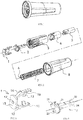
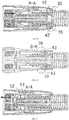
- the injection needle consists of a needle body 6, needle base 2, main cover 3, outer sheath 8, tail cover 1, front casing 4, trigger tube 5 and spring 7 (see Fig. 2 ).
- the needle body 6 is the needle to inject the insulin and the needle body 6 has an injection section extending in a forward direction, a connecting section extending in a rearward direction and a fixing section between the injection section and the connecting section;
- the needle base 2 is used to fix the needle body 6 (see Fig. 4 ) and the fixing section of needle body 6 is fixed on the needle base 2, the injection section of needle body 6 extends from the front end of needle base 2 and the connecting section of needle body 6 extends from the rear end of needle base 2;
- the needle base 2 consists of a seat plate 23 and a seat rod 24 and the seat rod 24 is located in the front end of seat plate 23 and connected with the seat plate 23 in a fixed way; the seat rod 24 is provided with a convex 22 and the seat plate 23 is provided with two dodging grooves 25, and the seat plate 23 is provided with a groove 21 in the circumferential direction.
- the main cover 3 is used to accommodate all components excluding the outer sheath 8 (see Fig. 5 ).
- the main cover 3 is the cylindrical structure and the needle base 2 and the needle body 6 are located in the main cover 3 under the assembly state.
- the inner wall of main cover 3 is provided with a first tenon stage 31 in the middle, a second tenon stage 35 in the front end and a third tenon stage 37 in the rear end and is provided with a anti-back slot 36 in the forepart and a dodging slot 32 in the forepart;
- the inner edge of main cover 3 is provided with a protruding rib 33 and slot 34, and the protruding rib 33 is located in the first positioning position in axial direction of main cover 3 and the slot 34 is located in the second positioning position in axial direction of main cover 3, and the distance from the first positioning position to the rear end of the main cover 3 is smaller than the distance from the second positioning position to the rear end of the main cover 3 based on rear end of main cover 3.
- the side wall of main cover 3 is provided with a bayonet 38, and the bayonet 38 is located in the second positioning position in axial direction of main cover 3 and the bayonet 38 is the through hole between the inner wall and outer wall of main cover 3 and the bayonet 38 is provided with a sliding channel 39 extending in the front end direction (to facilitate disconnection of the block 81 and the bayonet 38).
- the rear end of main cover 3 is used to connect the insulin pen and the connection structure may be the screw connection, plug-in connection and plug-in turn buckle connection, etc.
- the main cover 3 in Fig. 5 is the screw connection.
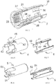
- the outer sheath 8 is used to protect the injection needle (see Fig. 10 ).
- the outer sheath 8 is a sleeve structure and the outer sheath 8 is installed at the outside of main cover 3 under the assembly state before use.
- the inner side of sleeve of outer sheath 8 is provided with a block 81, and the position of block 81 is corresponding to the bayonet 38 at the side wall of main cover 3, and when the outer sheath 8 is installed at the main cover 3, the block 81 is stuck in the bayonet 38 and extends into the main cover 3 to form the locking connection of outer sheath 8 and main cover 3.
- the inner wall of sleeve of outer sheath 8 is provided with the rib 82 protruding inward in axial direction and when the outer sheath 8 is installed at the outside of main cover 3, there is gap for deformation of outer sheath 8 between the inner wall of outer sheath 8 and outer wall of main cover 3.
- the tail cover 1 is used to protect the connecting section of needle body 6 (see Fig. 3 ).
- the tail cover 1 consists of a cap 15 and two front legs 16; the cap 15 is an end cap or a ring body and the center of the cap 15 is provided with a needle hole 17 for only inserting the needle body 6 connecting section so that the needle hole 17 axis is parallel to the main cover 3 axis; the two front legs 16 are fixedly attached to the front end of cap 15 and are arranged symmetrically with reference to the needle hole 17 axis, and the inner side of each front leg 16 is provided with a bevel 12 at the root position, a stopper 13 extending inward in the middle and a foot hook 11 in the end position; the outer side of each front leg 16 is provided with a sharp tenon 14 in the middle.
- the front casing 4 is used to protect the injection section of needle body 6 after use (see Fig. 6 and 7 ).
- the main structure of front casing 4 is the tubular body and the front casing 4 is provided with an inner end face 44 at the inner side of front end;
- the front casing 4 is provided with a flexible tenon 41 extending backward and a flexible tail fin 43 extending backward, and the flexible tenon 41 and the flexible tail fin 43 are arranged in a staggered way in the circumferential direction of front casing 4;
- the front casing 4 is provided with a convex 42 extending outward at the outer side in the middle and the convex 42 and the flexible tenon 41 are in the corresponding position in the circumferential direction of front casing 4 and the convex 42 is provided with a bevel 45 at the side of flexible tenon 41.
- the trigger tube 5 is used to protect the injection section of needle body 6 before use (see Fig. 8 and 9 ).
- the main structure of trigger tube 5 is the tubular body and the trigger tube 5 is provided with two inserts 52 extending backward at the rear end and the insert 52 is provided with a barb; the trigger tube 5 is provided with a recess 51 in the tubular body.
- the spring 7 is used to push the front casing 4 and tail cover 1.
- trigger tube 5 front casing 4, tail cover 1 and needle base 2 in the main cover 3:
- a third positioning structure formed by a concavo-convex structure is provided between the trigger tube 25 and the seat rod 24. That is, a recess 51 is set between the tubular body of trigger tube 5 and seat rod 24 at one side and a convex 22 is set at the other side and the recess 51 contacts the convex 22 to form a third positioning. At the same time, the flexible tenon 41 on the front casing 4 is stuck on the first tenon stage 31 on the main cover 3 to limit the forward movement of front casing 4 relative to the main cover 3.
- this structure resolves reliability issue of trigger tube 5 and front casing 4 protecting the injection section of needle body 6 before and during the use ensures the effective protection of safety of injection section of needle body 6 by the trigger tube 5 and front casing 4 before and during the use.
- the sliding positioning connection is designed to fix the needle base 2 of needle body 6 and the main cover 3. That is, the outer edge of the seat plate 23 of needle base 2 matches with the inner edge of the main cover 3, and the outer edge of corresponding seat plate 23 has a first positioning position and a second positioning position on the inner edge of main cover 3 in the axial direction; during the installation of injection needle to the insulin pen, it uses the axial thrust of tail cover 1 to the needle base 2 to push the seat plate 23 in the main cover 3 to move from the first positioning position to the second positioning position in the axial direction to form the sliding positioning connection relationship between the needle base 2 and main cover 3.
- the outer edge of seat plate 23 in the first positioning position matches with inner edge of main cover 3 through the first positioning structure and the outer edge of seat plate 23 in the second positioning position matches with inner edge of main cover 3 through the second positioning structure
- the first positioning structure is the concavo-convex positioning structure and the concavo-convex positioning structure is formed by a groove 21 provided in the circumferential direction of the outer edge of seat plate 23 and a protruding rib 33 provided on the inner edge of the main cover 3.
- the second positioning structure is the locking positioning structure and the locking positioning structure is formed by the outer edge and front and rear of seat plate 23 and the slot 34 at the inner edge of main cover 3.
- connection relationship uses the axial thrust of tail cover to the needle base 2 to push the seat plate 23 on the needle base 2 to move from the first positioning position to the second positioning position to correlate the information of installation of injection needle with the sliding position of seat plate 23 of needle base 2 in the main cover 3 during the installation of injection needle.
- tail cover 1 uses the movement of tail cover 1 to trigger the disconnection of front casing 4.
- this position relationship feature correlates the information of installation of injection needle with the movement of seat plate in the main cover and unlocking of trigger tube and front casing after the positioning and the correlation of unlocking of trigger tube and front casing after the positioning with the ready injection state of insulin pen and injection needle greatly improve the safety and convenience of injection needle.
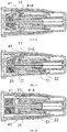
- the outer sheath 8 is installed at the outside of main cover 3, the block 81 of outer sheath 8 is stuck in the bayonet 38 of main cover 3 and extends into the main cover 3 to form the locking connection of outer sheath 8 and main cover 3; the needle base 2 and needle body 6 are located in the main cover 3, the seat plate 23 on the needle base 2 is located in the first positioning position in the main cover 3, and the groove 21 provided in the circumferential direction of the outer edge of seat plate 23 in the first positioning position and the protruding rib 33 provided on the inner edge of the main cover 3 form the concavo-convex positioning structure (see Fig.
- the tail cover 1 is located in the rear end of main cover 3, the cap 15 on the tail cover 1 is located in the back of seat plate 23 to protect the connecting section of needle body 6 (see Fig. 14 and 15 ) and the two front legs 16 on the tail cover 1 extends through the two dodging slots 25 of the seat plate 23 to the front (see Fig. 14 and 15 );
- the front casing 4 is located in the main cover 3, and the flexible tenon 41 of the front casing 4 is in the first tenon stage 31 of main cover 3 to limit the forward movement of front casing 4 in relative to the main cover 3 (see Fig. 16 ) and the foot hooks 11 of two front legs 16 of the tail cover 1 hook the flexible tenon 41 of front casing 4 (see Fig.
- the trigger tube 5 is located in the front end of main cover 3 and extends out of the front end to protect the injection section of needle body 6 (see Fig. 14 ) and the rear part of trigger tube 5 is installed on the seat rod 24 of needle base 2 and the rear part of trigger tube 5 is located in the front casing 4, and the front end of trigger tube 5 is close to or abutted against the front inner end face of the outer sheath 8, and the recess 51 is stuck in the convex 22 of seat rod 24 to form the positioning (see Fig. 15 and 16 ); the spring 7 is against the stopper 13 of two front legs 16 of tail cover 1 at one end and against the inner end face 44 of front casing 4 at the other end (see Fig. 14 ).
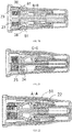
- Fig. 17 shows the state of first stage. From Fig. 17 , it's known that under this state, the user screws the insulin pen head to the injection needle of this embodiment. The insulin pen head pushes the tail cover 1 to move forward, and the arrow in Fig. 17 means the thrust generated by the insulin pen head and at the same time, the foot hook 11 of tail cover 1 is lifted by the bevel of convex 42 of front casing 4.
- Fig. 18 shows the state of second stage. From Fig. 18 , it's known that under such state, the insulin pen continues to screw in the injection needle, and the foot hook 11 of tail cover 1 crosses the convex 42 of front casing 4 and at the same time, the bevel 12 of tail cover 1 forces the flexible tenon 41 of front casing 4 bend inward.
- Fig. 19 and 20 show the state of third stage. Under such state, the insulin pen continues to screw in the injection needle and the flexible tenon 41 continues to bend inward, finally forcing the flexible tenon 41to disconnect from the first tenon stage 31 and fall in the dodging slot 32 and releasing the limit of forward movement of front casing 4 in the main cover 3, and at the same time, front casing 4 moves forward by the push of spring 7 until it stops moving by the convex 42 stopped by the foot hook 11 and limits the forward movement of front casing 4 (see Fig. 19 ). From Fig.
- Fig. 21, 22 and 23 show the state of Fourth stage. Under such state, the insulin pen continues to screw in the injection needle, the cap 15 of tail cover 1 is against the seat plate 23 of needle base 2 and pushes the seat plate 23 forward from first positioning position to second positioning position (see Fig. 21 ), and the matching of outer edge and front and rear of seat plate 23 in the second positioning position and the slot 34 at the inner edge of main cover 3 forms the locking positioning structure, and the seat plate 23 is locked in the second positioning position, which could not move forward or backward. Under such state, as the front end of trigger tube 5 is against the inner end face of outer sheath 8, when the needle base 2 moves forward, the positioning of convex 2 of needle base 2 and recess 51 of trigger tube 5 is unlocked (see Fig.
- Fig. 25 and 26 show the state of fifth stage. Under such state, remove the outer sheath 8 manually.
- Fig. 26 shows the state of sixth stage. Under such state, the trigger tube 5 contacts the human skin and the needle body 6 starts to penetrate into the human skin. When the front end of trigger tube 5 contacts the human skin, the trigger tube 5 moves backward and at the same time, the insert 52 of trigger tube 5 lifts the stopper 13 on the tail cover 1, forcing the foot hook 11 of tail cover 1 to gradually disconnect from the convex 42 of front casing 4.
- Fig. 27 shows the state of seventh stage. Under such state, the trigger tube 5 continues to move backward until the foot hook 11 completely disconnect from the convex 11 and then the front casing 4 moves forward by the spring 7 and extends out of the front end of main cover 3 and the front end of front casing 4 is blocked by the human skin and moves together with the front end of trigger tube.
- Fig. 28 shows the state of eighth stage. Under such state, the needle body 6 completely penetrates into the human skin and starts injecting the insulin.
- Fig. 29 and 30 show the state of ninth stage. Under such state, the injection needle is pulled out from the skin, and the front casing 4 is pushed out of the front end of main cover 3 by the spring 7 until the convex 42 of front casing 4 is stopped by the second tenon stage 35 on the main cover 3, and at this time, the front casing 4 is used to protect the injection section of needle body 6; At the same time, the flexible tail fin 43 of front casing 4 expands and is stuck in the anti-back slot 36 of main cover 3 to form the limit for the backward movement of front casing 4 to prevent the returning of front casing 4 (see Fig. 30 ).
- Fig. 31 shows the state of tenth stage. Under such state, the insulin pen is removed from the injection needle, the tail cover 1 moves backward by the spring 7and the two stoppers 13 on the tail cover 1 hold the inserts 52 of trigger tube 5 to move the trigger tube 5 backward.
- Fig. 32 shows the state after use. Under such state, the insulin pen is screwed out, the trigger tube 5 continues to move backward until the front end of seat rod 24 on the needle base 2 contacts the inner end face of trigger tube 5 to stop. Then the sharp tenon 14 on the tail cover 1 falls in the third tenon stage 37 of main cover 3 to form the limit for forward movement of tail cover 1, and the barbs of inserts 52 of trigger tube 5 match the stoppers to limit the backward movement of tail cover 1 in the back of main cover 3, and at this time, the tail cover 1 is used to protect the connecting section of needle body 6 and prevent the repeated use of injection needle.
- Embodiment 2 Insulin pen needle with front end needle tip protection As shown in Fig. 36 , the injection needle consists of a needle body 6, needle base 2, main cover 3, outer sheath 8, front casing 4, trigger tube 5 and spring 7.
- embodiment 2 only has the front end needle tip protection structure in comparison with embodiment 1 and it doesn't have the rear end needle tip protection structure. Specifically, the structure design has the following differences:
- the operation procedure of insulin injection needle in the embodiment 2 is described as follows: As shown in Fig. 38 and 39 , under the assembly state before use, the outer sheath 8 is installed at the outside of main cover 3, the block 81 of outer sheath 8 is stuck in the bayonet 38 of main cover 3 and extends into the main cover 3 to form the locking connection of outer sheath 8 and main cover 3; the needle base 2 and needle body 6 are located in the main cover 3, the seat plate 23 on the needle base 2 is located in the first positioning position in the main cover 3, and the groove 21 provided in the circumferential direction of the outer edge of seat plate 23 in the first positioning position and the protruding rib 33 provided on the inner edge of the main cover 3 form the concavo-convex positioning structure and the two front legs 16 on the seat plate 23 extends to the front; the front casing 4 is located in the main cover 3, and the flexible tenon 41 of the front casing 4 is in the first tenon stage 31 of main cover 3 to limit the forward movement of front casing 4 in relative to the
- the head of insulin pen pushes the seat plate 23 to move forward, and the bevel 12 of inner side of front leg 16 presses the flexible tenon 41 to bend inward to finally force the flexible tenon 41 to unhook from the first tenon stage 31 and fall in the dodging slot 32 to release the limit of forward movement of front casing 4 in the main cover 3 and at the same time, the front casing 4 is moved forward by the spring 7 until the convex 42 is stopped by the foot hook 11 to limit the forward movement of front casing 4; at the same time, the seat plate 23 moves forward from the first positioning position to the second positioning position, and the matching of outer edge and front and rear of seat plate 23 in the second positioning position and the slot 34 at the inner edge of main cover 3 forms the locking positioning structure, and the seat plate 23 is locked in the second positioning position, which could not move forward or backward.
- the front casing 4 when the injection needle is pulled out from the skin after the use, the front casing 4 is pushed out of the front end of main cover 3 by the spring 7 until the convex 42 of front casing 4 is stopped by the second tenon stage 35 on the main cover 3, and at this time, the front casing 4 is used to protect the injection section of needle body 6; at the same time, the flexible tail fin 43 of front casing 4 expands and is stuck in the anti-back slot 36 of main cover 3 to form the limit for the backward movement of front casing 4 to prevent the returning of front casing 4, and finally the injection needle is removed from the head of insulin pen.
Landscapes
- Health & Medical Sciences (AREA)
- Engineering & Computer Science (AREA)
- Animal Behavior & Ethology (AREA)
- General Health & Medical Sciences (AREA)
- Biomedical Technology (AREA)
- Heart & Thoracic Surgery (AREA)
- Hematology (AREA)
- Life Sciences & Earth Sciences (AREA)
- Vascular Medicine (AREA)
- Anesthesiology (AREA)
- Public Health (AREA)
- Veterinary Medicine (AREA)
- Environmental & Geological Engineering (AREA)
- Physics & Mathematics (AREA)
- General Physics & Mathematics (AREA)
- Theoretical Computer Science (AREA)
- Infusion, Injection, And Reservoir Apparatuses (AREA)
Claims (8)
- Insulininjektionsnadel mit einem Nadelspitzenschutz, umfassend:einen Nadelkörper (6), wobei der Nadelkörper (6) einen Injektionsabschnitt hat, der sich in einer Vorwärtsrichtung erstreckt, einen Verbindungsabschnitt, der sich in einer Rückwärtsrichtung erstreckt, und einen Befestigungsabschnitt zwischen dem Injektionsabschnitt und dem Verbindungsabschnitt;eine Nadelbasis (2), wobei die Nadelbasis (2) zur Befestigung des Nadelkörpers (6) verwendet wird, und der Befestigungsabschnitt des Nadelkörpers (6) an der Nadelbasis (2) befestigt ist, wobei sich der Injektionsabschnitt des Nadelkörpers (6) von dem vorderen Ende der Nadelbasis (2) erstreckt, und sich der Verbindungsabschnitt des Nadelkörpers (6) von dem hinteren Ende der Nadelbasis (2) erstreckt;eine Hauptabdeckung (3), wobei die Hauptabdeckung (3) aus einer zylindrischen Struktur besteht, in der die Nadelbasis (2) und der Nadelkörper (6) in einem zusammengefügten Zustand lokalisiert sind, und das hintere Ende der Hauptabdeckung (3) mit einem Insulinstift verbunden ist;wobei:die Nadelbasis (2) aus einer Sitzplatte (23) und einer Sitzstange (24) besteht, wobei die Sitzstange (24) in dem vorderen Ende der Sitzplatte (23) lokalisiert ist und mit der Sitzplatte (23) in einer befestigten Weise verbunden ist; wobei die Sitzplatte (23) mit zwei Umgehungsrillen (25) versehen ist, und der äußere Rand der Sitzplatte (23) zu dem innerne Rand der Hauptabdeckung (3) passt, und wobei der äußere Rand der entsprechenden Sitzplatte (23) eine erste Positionierposition und eine zweite Positionierposition an dem inneren Rand der Hauptabdeckung (3) mit einem Abstand in der axialen Richtung hat; wobei während der Installation der Injektionsnadel an dem Insulinstift der axiale Schub eines Kopfs des Insulinstifts zu der Nadelbasis (2) verwendet wird, um die Sitzplatte (23) in der Hauptabdeckung (3) zu einer Bewegung von der ersten Positionierposition zu der zweiten Positionierposition in der axialen Richtung zu drücken, um ein Gleitpositionierverbindungsverhältnis zwischen der Nadelbasis (2) und der Hauptabdeckung (3) zu bilden; wobei der äußere Rand der Sitzplatte (23) in der ersten Positionierposition zu dem inneren Rand der Hauptabdeckung (3) durch eine erste Positionierstruktur passt, wobei der äußere Rand der Sitzplatte (23) in der zweiten Positionierposition zu dem inneren Rand der Hauptabdeckung (3) durch eine zweite Positionierstruktur passt; wobei die erste Positionierstruktur eine konkav-konvexe Positionierstruktur, eine elastische Positionierstruktur, oder eine Reibpositionierstruktur ist; und wobei die zweite Positionierstruktur eine konkav-konvexe Positionierstruktur, eine elastische Positionierstruktur, eine Reibpositionierstruktur, eine Verriegelungspositionierstruktur oder eine Endflächenanschlagpositionierstruktur ist;wobei die innere Wand der Hauptabdeckung (3) mit einer ersten Zapfenstufe (31) in der Mitte, einer zweiten Zapfenstufe (35) an dem vorderen Ende, und einer dritten Zapfenstufe (37) an dem hinteren Ende versehen ist, und wobei die innere Wand der Hauptabdeckung (3) mit einem Gegenrückschlitz (36) in dem Vorderteil versehen ist;wobei die Hauptabdeckung (3) mit einer Heckabdeckung (1), einem vorderen Gehäuse (4), einem Triggerrohr (5) und einer Feder (7) versehen ist;wobei die Heckabdeckung (1) aus einer Kappe (15) und zwei vorderen Beinen (16) besteht; wobei die Kappe (15) eine Endkappe oder ein Ringkörper ist, und wobei die Mitte der Kappe (15) mit einem Nadelloch (17) zum Einsetzen nur des Nadelkörper (6) -Verbindungsabschnitts versehen ist, wobei die Achse des Nadellochs (17) parallel zur Achse der Hauptabdeckung (3) ist; wobei die zwei vorderen Beine (16) fest an dem vorderen Ende der Kappe (15) angebracht und symmetrisch mit Bezug zu der Achse des Nadellochs (17) angeordnet sind, und wobei die innere Seite von jedem vorderen Bein (16) mit einer Abschrägung (12) an der Wurzelposition versehen ist, einem Stopper (13), der sich einwärts in der Mitte erstreckt, und einem Fußhaken (11) an der Endposition; wobei die äußere Seite von jedem vorderen Bein (16) mit einem scharfen Zapfen (14) in der Mitte versehen ist;wobei die Hauptstruktur des vorderen Gehäuses (4) der Rohrkörper ist, und das vordere Gehäuse (4) mit einer inneren Endfläche (44) an der inneren Seite des vorderen Endes versehen ist; wobei das vordere Gehäuse (4) mit einem flexiblen Zapfen (41) versehen ist, der sich rückwärts erstreckt, und einer flexiblen Heckfinne (43), die sich rückwärts erstreckt, wobei der flexible Zapfen (41) und die flexible Heckfinne (43) in einer gestuften Weise in der Umfangsrichtung des vorderen Gehäuses (4) angeordnet sind; wobei das vorderen Gehäuse (4) mit einem konvexen Bereich (42) versehen ist, der sich auswärts an der äußeren Seite in der Mitte erstreckt, wobei der konvexe Bereich (42) und der flexible Zapfen (41) in der entsprechenden Position in der Umfangsrichtung des vorderen Gehäuses (4) sind, wobei der konvexe Bereich (42) mit einer Abschrägung (45) an der Seite des flexiblen Zapfens (41) versehen ist;wobei die Hauptstruktur des Triggerrohrs (5) ein Rohrkörper ist, wobei das Triggerrohr (5) mit zwei Einsätzen (52) versehen ist, die sich rückwärts an dem hinteren Ende erstrecken, wobei der Einsatz (52) mit einem Widerhaken versehen ist; wobei eine Aussparung (51) zwischen dem Rohrkörper des Triggerrohrs (5) und der Sitzstange (24) an einer Seite eingesetzt ist, und ein konvexer Bereich (22) an der anderen Seite eingesetzt ist, wobei die Aussparung (51) den konvexen Bereich (22) zum Bilden einer dritten Positionierung kontaktiert;wobei in dem zusammengefügten Zustand vor der Verwendung die Sitzplatte (23) in der ersten Positionierposition in der Hauptabdeckung (3) lokalisiert ist, die Heckabdeckung (1) in dem hinteren Ende der Hauptabdeckung (3) lokalisiert ist, die Kappe (15) an der Heckabdeckung (1) im hinteren Bereich der Sitzplatte (23) lokalisiert ist, um den Verbindungsabschnitt des Nadelkörpers (6) zu schützen, wobei die zwei vorderen Beine (16) an der Heckabdeckung (1) sich durch die zwei Umgehungsschlitze (25) der Sitzplatte (23) nach vorne erstrecken; wobei das vordere Gehäuse (4) in der Hauptabdeckung (3) lokalisiert ist, wobei der flexible Zapfen (41) des vorderen Gehäuses (4) in der ersten Zapfenstufe (31) der Hauptabdeckung (3) ist, um die Vorwärtsbewegung des vorderen Gehäuses (4) relativ zu der Hauptabdeckung (1) zu begrenzen, wobei die Fußhaken (11) der zwei vorderen Beine (16) der Heckabdeckung (1) die flexiblen Zapfen (41) des vorderen Gehäuses (4) einhaken; wobei das Triggerrohr (5) in dem vorderen Ende der Hauptabdeckung (3) lokalisiert ist, und sich aus dem vorderen Ende heraus erstreckt, um den Injektionsabschnitt des Nadelkörpers (6) zu schützen, wobei das Triggerrohr (5) mit einer Begrenzung für eine Vorwärtsbewegung relativ zu der Hauptabdeckung (3) versehen ist, wobei der hintere Teil des Triggerrohrs (5) an der Sitzstange (24) der Nadelbasis (2) befestigt ist, wobei der hintere Bereich des Triggerrohrs (5) in dem vorderen Gehäuse (4) lokalisiert ist, wobei das Triggerrohr (5) in der dritten Positionierposition lokalisiert ist, wobei die Sitzplatte (23) der Nadelbasis (2) in der ersten Positionierposition relativ zu der Hauptabdeckung (3) lokalisiert ist; wobei die Feder (7) gegen den Stopper (13) der zwei vorderen Beine (16) der Heckabdeckung (1) an einem Ende und gegen die innere Endfläche (44) des vorderen Gehäuses (4) an dem anderen Ende ist;wobei während der Verwendung und wenn die Injektionsnadel an dem Insulinstift installiert ist, der Kopf des Insulinstifts die Heckabdeckung (1) zu einer Vorwärtsbewegung drückt, der Fußhaken (11) der Heckabdeckung (1) durch die Abschrägung (45) des konvexen Bereichs (42) des vorderen Gehäuses (4) angehoben wird und dann über den konvexen Bereich (42) passiert, und die Abschrägung (12) der Heckabdeckung (1) den flexiblen Zapfen (12) für eine Biegung einwärts drückt, um schließlich den flexiblen Zapfen (41) für ein Aushaken von der ersten Zapfenstufe (31) zu drücken, um die Begrenzung der Vorwärtsbewegung des vorderen Gehäuses (4) in der Hauptabdeckung (3) aufzuheben, und wobei gleichzeitig das vordere Gehäuse (4) durch die Feder (7) vorwärtsbewegt wird, bis der konvexe Bereich (42) durch den Fußhaken (11) gestoppt wird, um die Vorwärtsbewegung des vorderen Gehäuses (4) zu begrenzen, und dann die Kappe (15) der Heckabdeckung (1) die Sitzplatte (23) der Nadelbasis (2) kontaktiert und die Sitzplatte (23) zur Bewegung vorwärts von der ersten Positionierposition zu der zweiten Positionierposition drückt, und da das Triggerrohr (5) durch die Vorwärtsbewegungsbegrenzung begrenzt wird, wenn sich die Nadelbasis (2) vorwärts bewegt, das Triggerrohr (5) und die Sitzstange (24) die dritte Positionierung lösen und eine Gleitverbindung bilden; und dann, wenn das vordere Ende des Triggerrohrs (5) die Haut eines menschlichen Körpers kontaktiert, das Triggerrohr (5) sich rückwärts bewegt und der Einsatz (52) des Triggerrohrs (5) den Stopper (13) an der Heckabdeckung (1) anhebt, um den Fußhaken (11) der Heckabdeckung (1) für eine schrittweise Separierung von dem konvexen Bereich (42) des vorderen Gehäuses (4) zu drücken, bis eine vollständige Separierung erreicht ist, so dass sich das vordere Gehäuse (4) durch die Feder (7) vorwärts bewegt und sich durch das vordere Ende der Hauptabdeckung (3) erstreckt, und das vordere Ende des vorderen Gehäuses (4) durch die Haut des menschlichen Körpers blockiert wird und sich zusammen mit dem vorderen Ende des Triggerrohrs (5) bewegt, bis die Nadel in die Haut penetriert, um das Insulin zu injizieren;wobei dann, wenn die Injektionsnadel nach der Verwendung aus der Haut herausgezogen wird, das vordere Gehäuse (4) aus dem vorderen Ende der Hauptabdeckung (3) durch die Feder (7) herausgedrückt wird, bis der konvexe Bereich (42) des vorderen Gehäuses (4) durch die zweite Zapfenstufe (35) an der Hauptabdeckung (3) gestoppt wird, und zu diesem Zeitpunkt das vorderen Gehäuse (4) verwendet wird, um den Injektionsabschnitt des Nadelkörpers (6) zu schützen; und gleichzeitig die flexible Heckfinne (43) des vorderen Gehäuses (4) expandiert und in dem Gegenrückschlitz (36) der Hauptabdeckung (3) steckt, um eine Begrenzung für die Rückwärtsbewegung des vorderen Gehäuses (4) zu bilden, um die Rückkehr des vorderen Gehäuses (4) zu verhindern;wobei dann, wenn die Injektionsnadel nach der Verwendung von dem Kopf des Insulinstifts entfernt wird, die Heckabdeckung (1) sich rückwärts durch die Feder (7) bewegt und die zwei Stopper (13) an der Heckabdeckung (1) die Einsätze (52) des Triggerrohrs (5) halten, um das Triggerrohr (5) rückwärts zu bewegen, bis das vordere Ende der Sitzstange (24) an der Nadelbasis (2) die innere Endfläche des Triggerrohrs (5) für einen Stopp kontaktiert; und dann der scharfe Zapfen (14) an der Heckabdeckung (1) in die dritte Zapfenstufe (37) der Hauptabdeckung (3) fällt, um eine Begrenzung für eine Vorwärtsbewegung der Heckabdeckung (1) zu bilden, und die Widerhaken der Einsätze (52) des Triggerrohrs (5) zu den Stoppern (13) passen, um die Rückwärtsbewegung der Heckabdeckung (1) in den hinteren Bereich der Hauptabdeckung (3) zu begrenzen, und zu diesem Zeitpunkt die Heckabdeckung (1) verwendet wird, um den Verbindungsabschnitt des Nadelkörpers (6) zu schützen und die wiederholte Verwendung der Injektionsnadel zu verhindern.
- Insulininjektionsnadel mit einem Nadelspitzenschutz, umfassend:einen Nadelkörper (6), wobei der Nadelkörper (6) einen Injektionsabschnitt hat, der sich in einer Vorwärtsrichtung erstreckt, einen Verbindungsabschnitt, der sich in einer Rückwärtsrichtung erstreckt, und einen Befestigungsabschnitt zwischen dem Injektionsabschnitt und dem Verbindungsabschnitt;eine Nadelbasis (2), wobei die Nadelbasis (2) zur Befestigung des Nadelkörpers (6) verwendet wird, und der Befestigungsabschnitt des Nadelkörpers (6) an der Nadelbasis (2) befestigt ist, wobei sich der Injektionsabschnitt des Nadelkörpers (6) von dem vorderen Ende der Nadelbasis (2) erstreckt, und sich der Verbindungsabschnitt des Nadelkörpers (6) von dem hinteren Ende der Nadelbasis (2) erstreckt;eine Hauptabdeckung (3), wobei die Hauptabdeckung (3) aus einer zylindrischen Struktur besteht, in der die Nadelbasis (2) und der Nadelkörper (6) in einem zusammengefügten Zustand lokalisiert sind, und das hintere Ende der Hauptabdeckung (3) mit einem Insulinstift verbunden ist;wobei:die Nadelbasis (2) aus einer Sitzplatte (23), einer Sitzstange (24) und zwei vorderen Beinen (16) besteht; und die Sitzstange (24) in dem vorderen Ende der Sitzplatte (23) lokalisiert ist und mit der Sitzplatte (23) in einer befestigten Weise verbunden ist; wobei die zwei vorderen Beine (16) symmetrisch an zwei Seiten der Sitzstange (24) angeordnet sind, und die Wurzeln der zwei vorderen Beine (16) fest an der Sitzplatte (23) angebracht sind, und die innere Seite von jedem vorderen Bein (16) mit einer Abschrägung (12) an der Wurzelposition versehen ist, einem Stopper (13), der sich einwärts in der Mitte erstreckt, und einem Fußhaken (11) in der Endposition; und wobei der äußere Rand der Sitzplatte (23) zu dem inneren Rand der Hauptabdeckung (3) passt, und der äußere Rand der entsprechenden Sitzplatte (23) eine erste Positionierposition und eine zweite Positionierposition an dem inneren Rand der Hauptabdeckung (3) mit einem Abstand in der axialen Richtung hat; wobei während der Installation der Injektionsnadel an dem Insulinstift der axiale Schub des Insulinstiftkopfs auf die Sitzplatte (23) verwendet wird, um die Sitzplatte (23) in der Hauptabdeckung (3) zu einer Bewegung von der ersten Positionierposition zu der zweiten Positionierposition in der axialen Richtung zu drücken, um ein Gleitpositionierverbindungsverhältnis zwischen der Nadelbasis (2) und der Hauptabdeckung (3) zu bilden; wobei der äußere Rand der Sitzplatte (23) in der ersten Positionierposition zum inneren Rand der Hauptabdeckung (3) durch die erste Positionierstruktur passt, und der äußere Rand der Sitzplatte (23) in der zweiten Positionierposition zum inneren Rand der Hauptabdeckung (3) durch die zweite Positionierstruktur passt; wobei die erste Positionierstruktur eine konkav-konvexe Positionierstruktur, eine elastische Positionierstruktur, oder eine Reibpositionierstruktur ist; und wobei die zweite Positionierstruktur eine konkav-konvexe Positionierstruktur, eine elastische Positionierstruktur, eine Reibpositionierstruktur, eine Verriegelungspositionierstruktur oder eine Endflächenanschlagspositionierstruktur ist;wobei die innere Wand der Hauptabdeckung (3) mit einer ersten Zapfenstufe (31) in der Mitte und einer zweiten Zapfenstufe (35) in dem vorderen Ende versehen ist, und mit einem Gegenrückschlitz (36) in dem Vorderteil versehen ist;wobei die Hauptabdeckung (3) mit einem vorderen Gehäuse (4), einem Triggerrohr (5) und einer Feder (7) versehen ist;wobei die Hauptstruktur des vorderen Gehäuses (4) ein Rohrkörper ist, und das vordere Gehäuse (4) mit einer inneren Endfläche (44) an der inneren Seite des vorderen Endes versehen ist; wobei das vordere Gehäuse (4) mit einem flexiblen Zapfen (41) versehen ist, der sich rückwärts erstreckt, und einer flexiblen Heckfinne (43), die sich rückwärts erstreckt, und wobei der flexible Zapfen (41) und die flexible Heckfinne (43) in einer abgestuften Weise in der Umfangsrichtung des vorderen Gehäuses (4) angeordnet sind; wobei das vordere Gehäuse (4) mit einem konvexen Bereich (42) versehen ist, der sich auswärts an der Außenseite in der Mitte erstreckt, und der konvexe Bereich (42) und der flexible Zapfen (41) in der entsprechenden Position in der Umfangsrichtung des vorderen Gehäuses (4) sind;wobei die Hauptstruktur des Triggerrohrs (5) ein Rohrkörper ist, und das Triggerrohr (5) mit zwei Einsätzen (52) versehen ist, die sich rückwärts an dem hinteren Ende erstrecken, und der Einsatz (52) mit einem Widerhaken versehen ist; wobei eine Aussparung (51) zwischen dem Rohrkörper des Triggerrohrs (5) und der Sitzstange (24) an einer Seite eingesetzt ist, und ein konvexer Bereich (22) an der anderen Seite eingesetzt ist, und wobei die Aussparung (51) den konvexen Bereich (22) kontaktiert, um eine dritte Positionierung zu bilden;wobei in einem zusammengefügten Zustand vor der Verwendung die Sitzplatte (23) in der ersten Positionierposition in der Hauptabdeckung (3) lokalisiert ist, und die zwei vorderen Beine (16) an der Sitzplatte (23), die sich vorwärts erstrecken, sich nach vorne erstrecken; wobei das vordere Gehäuse (4) in der Hauptabdeckung (3) lokalisiert ist, und der flexible Zapfen (41) des vorderen Gehäuses (4) in der ersten Zapfenstufe (31) der Hauptabdeckung (3) ist, um eine Vorwärtsbewegung des vorderen Gehäuses (4) relativ zur Hauptabdeckung (3) zu begrenzen; wobei das Triggerrohr (5) in dem vorderen Ende der Hauptabdeckung (3) lokalisiert ist und sich aus dem vorderen Ende heraus erstreckt, um den Injektionsabschnitt des Nadelkörpers (6) zu schützen, und wobei das Triggerrohr (5) mit einer Begrenzungsposition für eine Vorwärtsbewegung relativ zur Hauptabdeckung (3) versehen ist, und wobei der hintere Teil des Triggerrohrs (5) an der Sitzstange (24) der Nadelbasis (2) befestigt ist, wobei der hintere Bereich des Triggerrohrs (5) in dem vorderen Gehäuse (4) lokalisiert ist, wobei das Triggerrohr (5) in der dritten Positionierposition lokalisiert ist, und die Sitzplatte (23) der Nadelbasis (2) in der ersten Positionierposition relativ zu der Hauptabdeckung (3) lokalisiert ist; wobei die Feder (7) gegen den Stopper (13) der zwei vorderen Beine (16) der Nadelbasis (1) an einem Ende und gegen die innere Endfläche (44) des vorderen Gehäuses (4) an dem anderen Ende ist;wobei während der Verwendung und wenn die Injektionsnadel an dem Insulinstift installiert ist, der Kopf des Insulinstifts die Sitzplatte (23) für eine Bewegung nach vorne drückt, und die Abschrägung (12) der inneren Seite des vorderen Beins (16) den flexiblen Zapfen (41) für eine Biegung einwärts drückt, um schließlich den flexiblen Zapfen (41) für ein Aushaken von der ersten Zapfenstufe (31) zu drücken, um die Begrenzung der Vorwärtsbewegung des vorderen Gehäuses (4) in der Hauptabdeckung (3) zu lösen, und gleichzeitig das vordere Gehäuse (4) vorwärts durch die Feder (7) bewegt wird, bis der konvexe Bereich (42) durch den Fußhaken (11) gestoppt wird, um die Vorwärtsbewegung des vorderen Gehäuses (4) zu begrenzen; und gleichzeitig die Sitzplatte (23) sich vorwärts von der ersten Positionierposition zu der zweiten Positionierposition bewegt, und da das Triggerrohr (5) durch die Vorwärtsbewegungsbegrenzung begrenzt wird, wenn die Nadelbasis (2) sich vorwärts bewegt, das Triggerrohr (5) und die Sitzstange (24) die dritte Positionierung lösen und eine Gleitverbindung bilden; und dann, wenn das vordere Ende des Triggerrohrs (5) die Haut eines menschlichen Körpers kontaktiert, das Triggerrohr (5) sich rückwärts bewegt und der Einsatz (52) des Triggerrohrs (5) den Stopper (13) an dem vorderen Bein (16) anhebt, um den Fußhaken (11) des vorderen Beins (16) für eine schrittweise Separierung von dem konvexen Bereich (42) des vorderen Gehäuses (4) zu drücken, bis eine vollständige Separierung erreicht ist, so dass das vordere Gehäuse (4) sich vorwärts durch die Feder (7) bewegt und sich durch das vordere Ende der Hauptabdeckung (3) erstreckt, und das vordere Ende des vorderen Gehäuses (4) durch die Haut des menschlichen Körpers blockiert wird und sich zusammen mit dem vorderen Ende des Triggerrohrs (5) bewegt, bis die Nadel in die Haut penetriert, um das Insulin zu injizieren;wobei dann, wenn die Injektionsnadel nach der Verwendung aus der Haut herausgezogen wird, das vordere Gehäuse (4) aus dem vorderen Ende der Hauptabdeckung (3) durch die Feder (7) herausgedrückt wird, bis der konvexe Bereich (42) des vorderen Gehäuses (4) durch die zweite Zapfenstufe (35) an der Hauptabdeckung (3) gestoppt wird, und zu diesem Zeitpunkt das vordere Gehäuse (4) verwendet wird, um den Injektionsabschnitt des Nadelkörpers (6) zu schützen; und gleichzeitig die flexible Heckfinne (43) des vorderen Gehäuses (4) expandiert und in dem Gegenrückschlitz (36) der Hauptabdeckung (3) steckt, um eine Begrenzung für eine Rückwärtsbewegung des vorderen Gehäuses (4) zu bilden, um die Rückkehr des vorderen Gehäuses (4) zu verhindern, und schließlich die Injektionsnadel von dem Kopf des Insulinstifts entfernt wird.
- Injektionsnadel nach Anspruch 1 oder 2, wobei die konkav-konvexe Positionierstruktur durch eine Rille (21) gebildet ist, die in der Umfangsrichtung des äußeren Rands der Sitzplatte (23) vorgesehen ist, und eine vorstehende Rippe (33), die an dem inneren Rand der Hauptabdeckung (3) vorgesehen ist.
- Injektionsnadel nach Anspruch 1 oder 2, wobei die elastische Positionierstruktur durch Zusammenpassen eines elastischen Wulststifts und eines Grübchens gebildet ist, wobei von dem elastischen Wulststift und dem Grübchen, eines in dem äußeren Rand der Sitzplatte (23) eingesetzt ist, und das andere in dem inneren Rand der Hauptabdeckung (3) eingesetzt ist.
- Injektionsnadel nach Anspruch 1 oder 2, wobei die Reibpositionierstruktur durch die Reibpassung des äußeren Rands der Sitzplatte (23) und des inneren Rands der Hauptabdeckung (3) gebildet ist.
- Injektionsnadel nach Anspruch 1 oder 2, wobei die Verriegelungspositionierstruktur durch die Passung des äußeren Rands und des vorderen Bereichs und des hinteren Bereichs der Sitzplatte (23) und des Schlitzes (34) an dem inneren Rand der Hauptabdeckung (3) gebildet ist.
- Injektionsnadel nach Anspruch 1 oder 2, wobei die Endflächenanschlagspositionierstruktur durch die Anschlagspassung des vorderen Endes am äußeren Rand der Sitzplatte (23) und der inneren Endfläche am inneren Rand der Hauptabdeckung (3) gebildet ist.
- Injektionsnadel nach Anspruch 1 oder 2, wobei die Hauptabdeckung (3) mit einem äußeren Mantel (8) versehen ist, welcher (8) eine Hülsenstruktur hat, und wobei der äußere Mantel (8) an der Außenseite der Hauptabdeckung (3) im zusammengefügten Zustand vor der Verwendung installiert ist, um die Injektionsnadel zu schützen; wobei das Triggerrohr (5) mit einer Vorwärtsbewegungsbegrenzung relativ zur Hauptabdeckung (3) versehen ist, die dadurch gebildet ist, dass das vordere Ende des Triggerrohrs (5) nahe der oder im Anschlag gegen die vordere innere Endfläche des äußeren Mantels (8) ist.
Applications Claiming Priority (2)
| Application Number | Priority Date | Filing Date | Title |
|---|---|---|---|
| CN201510209194.0A CN104771815B (zh) | 2015-04-28 | 2015-04-28 | 带针尖保护的胰岛素注射针头 |
| PCT/CN2016/078194 WO2016173384A1 (zh) | 2015-04-28 | 2016-03-31 | 带针尖保护的胰岛素注射针头 |
Publications (3)
| Publication Number | Publication Date |
|---|---|
| EP3290076A1 EP3290076A1 (de) | 2018-03-07 |
| EP3290076A4 EP3290076A4 (de) | 2018-10-31 |
| EP3290076B1 true EP3290076B1 (de) | 2020-05-06 |
Family
ID=53613782
Family Applications (1)
| Application Number | Title | Priority Date | Filing Date |
|---|---|---|---|
| EP16785815.8A Not-in-force EP3290076B1 (de) | 2015-04-28 | 2016-03-31 | Insulininjektionsnadel mit nadelspitzenschutzfunktion |
Country Status (5)
| Country | Link |
|---|---|
| US (1) | US11020535B2 (de) |
| EP (1) | EP3290076B1 (de) |
| CN (1) | CN104771815B (de) |
| BR (1) | BR112017023120B1 (de) |
| WO (1) | WO2016173384A1 (de) |
Families Citing this family (23)
| Publication number | Priority date | Publication date | Assignee | Title |
|---|---|---|---|---|
| EP2572741A1 (de) * | 2011-09-23 | 2013-03-27 | Sanofi-Aventis Deutschland GmbH | Medikamentenabgabevorrichtung und Auslösemechanismus für eine Medikamentenabgabevorrichtung |
| CN104771815B (zh) | 2015-04-28 | 2017-05-03 | 苏州施莱医疗器械有限公司 | 带针尖保护的胰岛素注射针头 |
| CN104771813B (zh) * | 2015-04-28 | 2017-08-22 | 苏州施莱医疗器械有限公司 | 一次性安全胰岛素注射针头 |
| US10279123B2 (en) * | 2015-10-01 | 2019-05-07 | Noble International, Inc. | Microcartridge |
| US10363378B2 (en) * | 2016-06-15 | 2019-07-30 | Shl Medical Ag | Cap assembly for medicament delivery device |
| CN107050572B (zh) * | 2017-05-03 | 2024-03-01 | 贝普医疗科技股份有限公司 | 一种医用注射器 |
| CN107050573A (zh) * | 2017-05-03 | 2017-08-18 | 贝普医疗科技有限公司 | 一种医用注射器 |
| CN107174698B (zh) * | 2017-05-03 | 2024-07-05 | 贝普医疗科技股份有限公司 | 一种医用注射器 |
| CN107469188B (zh) * | 2017-08-03 | 2023-04-18 | 安徽迈菲思医疗器械有限公司 | 一种安全针 |
| CN108543169B (zh) | 2018-05-16 | 2023-12-01 | 普昂(杭州)医疗科技股份有限公司 | 一种安全式胰岛素笔针 |
| CN110681006A (zh) * | 2018-07-06 | 2020-01-14 | 群康生技股份有限公司 | 注射器 |
| CN109701120B (zh) * | 2018-12-12 | 2024-03-29 | 苏州施莱医疗器械有限公司 | 安全注射针 |
| CN109452981B (zh) * | 2018-12-26 | 2024-04-30 | 常州赛乐医疗技术有限公司 | 一种感应加热的牙胶充填仪 |
| CN209967279U (zh) | 2018-12-27 | 2020-01-21 | 宁波美生医疗器材有限公司 | 一种安全型注射装置和注射器 |
| CN109718429B (zh) * | 2019-02-15 | 2024-01-16 | 贝普医疗科技股份有限公司 | 一种安全胰岛素针 |
| CN109924952B (zh) * | 2019-04-30 | 2025-04-29 | 三诺生物传感股份有限公司 | 一种植入工具推针结构和植入式传感器用植入工具 |
| CN110141733B (zh) * | 2019-05-10 | 2023-06-30 | 山东连发医用塑胶制品有限公司 | 一种安全胰岛素注射针头 |
| USD911518S1 (en) * | 2019-07-31 | 2021-02-23 | Shali Medical (Suzhou) Inc. | Needle shield |
| CN111330117B (zh) * | 2020-03-12 | 2022-01-18 | 江苏谦元医疗科技有限公司 | 安全型胰岛素针头 |
| US12005244B2 (en) | 2020-03-27 | 2024-06-11 | Medivena Sp. Z O.O. | Needle-based device based on direct wing-based coupling of a needle shield to a barrel thereof and safety mechanism implemented therein |
| CN116870299B (zh) * | 2023-06-02 | 2025-09-02 | 四川大学华西医院 | 一种安全便捷式胰岛素注射笔 |
| CN117100949B (zh) * | 2023-09-26 | 2024-02-23 | 安徽宏宇五洲医疗器械股份有限公司 | 一种带安全防护式自主注射通用注射针头 |
| CN117323510A (zh) * | 2023-11-14 | 2024-01-02 | 江苏采纳医疗科技有限公司 | 前端防针刺胰岛素笔针 |
Family Cites Families (9)
| Publication number | Priority date | Publication date | Assignee | Title |
|---|---|---|---|---|
| US6986760B2 (en) * | 2000-08-02 | 2006-01-17 | Becton, Dickinson And Company | Pen needle and safety shield system |
| EP1448256B1 (de) * | 2001-11-30 | 2006-01-25 | Novo Nordisk A/S | Nadelsicherheitsvorrichtung |
| GB0600212D0 (en) * | 2006-01-06 | 2006-02-15 | Liversidge Barry P | Medical needle safety device |
| DE102006042233B3 (de) * | 2006-09-06 | 2008-03-06 | Tecpharma Licensing Ag | Nadelschutzvorrichtung mit distalem und proximalem Nadelschutz |
| US9642971B2 (en) * | 2008-03-13 | 2017-05-09 | Becton, Dickinson And Company | Safety needle assembly |
| EP2361648A1 (de) * | 2010-02-18 | 2011-08-31 | Sanofi-Aventis Deutschland GmbH | Entfernung eines schützenden Nadelschirms |
| CN104307072A (zh) * | 2014-10-29 | 2015-01-28 | 杭州普昂医疗科技有限公司 | 安全式胰岛素笔针 |
| CN104771815B (zh) | 2015-04-28 | 2017-05-03 | 苏州施莱医疗器械有限公司 | 带针尖保护的胰岛素注射针头 |
| CN204995929U (zh) * | 2015-04-28 | 2016-01-27 | 苏州施莱医疗器械有限公司 | 带针尖保护的胰岛素注射针头 |
-
2015
- 2015-04-28 CN CN201510209194.0A patent/CN104771815B/zh active Active
-
2016
- 2016-03-31 EP EP16785815.8A patent/EP3290076B1/de not_active Not-in-force
- 2016-03-31 US US15/570,521 patent/US11020535B2/en active Active
- 2016-03-31 BR BR112017023120-4A patent/BR112017023120B1/pt not_active IP Right Cessation
- 2016-03-31 WO PCT/CN2016/078194 patent/WO2016173384A1/zh not_active Ceased
Non-Patent Citations (1)
| Title |
|---|
| None * |
Also Published As
| Publication number | Publication date |
|---|---|
| BR112017023120B1 (pt) | 2022-08-02 |
| US11020535B2 (en) | 2021-06-01 |
| BR112017023120A2 (pt) | 2018-07-10 |
| EP3290076A4 (de) | 2018-10-31 |
| WO2016173384A1 (zh) | 2016-11-03 |
| CN104771815A (zh) | 2015-07-15 |
| CN104771815B (zh) | 2017-05-03 |
| US20180147365A1 (en) | 2018-05-31 |
| EP3290076A1 (de) | 2018-03-07 |
Similar Documents
| Publication | Publication Date | Title |
|---|---|---|
| EP3290076B1 (de) | Insulininjektionsnadel mit nadelspitzenschutzfunktion | |
| EP3815727B1 (de) | Drehbare verriegelbare insulininjektionsnadel | |
| CN104771814B (zh) | 一次性安全型胰岛素注射针头 | |
| US10835676B2 (en) | Push button safety injector | |
| JP6599359B2 (ja) | 自動注入器 | |
| CN104771813B (zh) | 一次性安全胰岛素注射针头 | |
| CN108992745B (zh) | 转动锁定式安全胰岛素注射针头 | |
| US9687616B2 (en) | Autoinjector | |
| US20110022001A1 (en) | Pen needle assembly | |
| US20100185147A1 (en) | Disposable safety syringe structure | |
| CN109316650B (zh) | 改进型转动式安全胰岛素注射针头 | |
| WO2019080822A1 (zh) | 一种防止误操作卸针的采血笔 | |
| CN107921240B (zh) | 手动式静脉留置针组 | |
| CN108371738B (zh) | 安全胰岛素注射针头 | |
| CN108211051B (zh) | 一种可换针头式回缩型安全注射器 | |
| WO2020006751A1 (zh) | 注射器 | |
| CN205007385U (zh) | 一次性安全胰岛素注射针头 | |
| KR102675223B1 (ko) | 다기능 바늘 홀더 및 리테이너 링 조립체를 가지는 주사기 | |
| CN114502217A (zh) | 安全注射装置 | |
| US20080167612A1 (en) | Intravenous catheter introducing device | |
| CA2429753C (en) | Disposable syringe | |
| CN217854076U (zh) | 一种自动注射器 | |
| AU2003204251A1 (en) | Disposable syringe |
Legal Events
| Date | Code | Title | Description |
|---|---|---|---|
| STAA | Information on the status of an ep patent application or granted ep patent |
Free format text: STATUS: THE INTERNATIONAL PUBLICATION HAS BEEN MADE |
|
| PUAI | Public reference made under article 153(3) epc to a published international application that has entered the european phase |
Free format text: ORIGINAL CODE: 0009012 |
|
| STAA | Information on the status of an ep patent application or granted ep patent |
Free format text: STATUS: REQUEST FOR EXAMINATION WAS MADE |
|
| 17P | Request for examination filed |
Effective date: 20171128 |
|
| AK | Designated contracting states |
Kind code of ref document: A1 Designated state(s): AL AT BE BG CH CY CZ DE DK EE ES FI FR GB GR HR HU IE IS IT LI LT LU LV MC MK MT NL NO PL PT RO RS SE SI SK SM TR |
|
| AX | Request for extension of the european patent |
Extension state: BA ME |
|
| DAV | Request for validation of the european patent (deleted) | ||
| DAX | Request for extension of the european patent (deleted) | ||
| A4 | Supplementary search report drawn up and despatched |
Effective date: 20181004 |
|
| RIC1 | Information provided on ipc code assigned before grant |
Ipc: B42D 15/00 20060101ALI20180927BHEP Ipc: A61M 5/34 20060101ALI20180927BHEP Ipc: A61M 5/32 20060101AFI20180927BHEP Ipc: G09F 1/04 20060101ALI20180927BHEP Ipc: A61M 5/00 20060101ALI20180927BHEP |
|
| RIC1 | Information provided on ipc code assigned before grant |
Ipc: A61M 5/00 20060101ALI20190806BHEP Ipc: A61M 5/34 20060101ALI20190806BHEP Ipc: A61M 5/32 20060101AFI20190806BHEP Ipc: B42D 15/00 20060101ALI20190806BHEP Ipc: G09F 1/04 20060101ALI20190806BHEP |
|
| GRAP | Despatch of communication of intention to grant a patent |
Free format text: ORIGINAL CODE: EPIDOSNIGR1 |
|
| STAA | Information on the status of an ep patent application or granted ep patent |
Free format text: STATUS: GRANT OF PATENT IS INTENDED |
|
| INTG | Intention to grant announced |
Effective date: 20191017 |
|
| GRAS | Grant fee paid |
Free format text: ORIGINAL CODE: EPIDOSNIGR3 |
|
| GRAA | (expected) grant |
Free format text: ORIGINAL CODE: 0009210 |
|
| STAA | Information on the status of an ep patent application or granted ep patent |
Free format text: STATUS: THE PATENT HAS BEEN GRANTED |
|
| AK | Designated contracting states |
Kind code of ref document: B1 Designated state(s): AL AT BE BG CH CY CZ DE DK EE ES FI FR GB GR HR HU IE IS IT LI LT LU LV MC MK MT NL NO PL PT RO RS SE SI SK SM TR |
|
| REG | Reference to a national code |
Ref country code: GB Ref legal event code: FG4D |
|
| REG | Reference to a national code |
Ref country code: CH Ref legal event code: EP Ref country code: AT Ref legal event code: REF Ref document number: 1265780 Country of ref document: AT Kind code of ref document: T Effective date: 20200515 |
|
| REG | Reference to a national code |
Ref country code: IE Ref legal event code: FG4D |
|
| REG | Reference to a national code |
Ref country code: DE Ref legal event code: R096 Ref document number: 602016035963 Country of ref document: DE |
|
| REG | Reference to a national code |
Ref country code: LT Ref legal event code: MG4D |
|
| REG | Reference to a national code |
Ref country code: NL Ref legal event code: MP Effective date: 20200506 |
|
| PG25 | Lapsed in a contracting state [announced via postgrant information from national office to epo] |
Ref country code: SE Free format text: LAPSE BECAUSE OF FAILURE TO SUBMIT A TRANSLATION OF THE DESCRIPTION OR TO PAY THE FEE WITHIN THE PRESCRIBED TIME-LIMIT Effective date: 20200506 Ref country code: GR Free format text: LAPSE BECAUSE OF FAILURE TO SUBMIT A TRANSLATION OF THE DESCRIPTION OR TO PAY THE FEE WITHIN THE PRESCRIBED TIME-LIMIT Effective date: 20200807 Ref country code: LT Free format text: LAPSE BECAUSE OF FAILURE TO SUBMIT A TRANSLATION OF THE DESCRIPTION OR TO PAY THE FEE WITHIN THE PRESCRIBED TIME-LIMIT Effective date: 20200506 Ref country code: IS Free format text: LAPSE BECAUSE OF FAILURE TO SUBMIT A TRANSLATION OF THE DESCRIPTION OR TO PAY THE FEE WITHIN THE PRESCRIBED TIME-LIMIT Effective date: 20200906 Ref country code: PT Free format text: LAPSE BECAUSE OF FAILURE TO SUBMIT A TRANSLATION OF THE DESCRIPTION OR TO PAY THE FEE WITHIN THE PRESCRIBED TIME-LIMIT Effective date: 20200907 Ref country code: FI Free format text: LAPSE BECAUSE OF FAILURE TO SUBMIT A TRANSLATION OF THE DESCRIPTION OR TO PAY THE FEE WITHIN THE PRESCRIBED TIME-LIMIT Effective date: 20200506 Ref country code: NO Free format text: LAPSE BECAUSE OF FAILURE TO SUBMIT A TRANSLATION OF THE DESCRIPTION OR TO PAY THE FEE WITHIN THE PRESCRIBED TIME-LIMIT Effective date: 20200806 |
|
| PG25 | Lapsed in a contracting state [announced via postgrant information from national office to epo] |
Ref country code: LV Free format text: LAPSE BECAUSE OF FAILURE TO SUBMIT A TRANSLATION OF THE DESCRIPTION OR TO PAY THE FEE WITHIN THE PRESCRIBED TIME-LIMIT Effective date: 20200506 Ref country code: HR Free format text: LAPSE BECAUSE OF FAILURE TO SUBMIT A TRANSLATION OF THE DESCRIPTION OR TO PAY THE FEE WITHIN THE PRESCRIBED TIME-LIMIT Effective date: 20200506 Ref country code: BG Free format text: LAPSE BECAUSE OF FAILURE TO SUBMIT A TRANSLATION OF THE DESCRIPTION OR TO PAY THE FEE WITHIN THE PRESCRIBED TIME-LIMIT Effective date: 20200806 Ref country code: RS Free format text: LAPSE BECAUSE OF FAILURE TO SUBMIT A TRANSLATION OF THE DESCRIPTION OR TO PAY THE FEE WITHIN THE PRESCRIBED TIME-LIMIT Effective date: 20200506 |
|
| REG | Reference to a national code |
Ref country code: AT Ref legal event code: MK05 Ref document number: 1265780 Country of ref document: AT Kind code of ref document: T Effective date: 20200506 |
|
| PG25 | Lapsed in a contracting state [announced via postgrant information from national office to epo] |
Ref country code: AL Free format text: LAPSE BECAUSE OF FAILURE TO SUBMIT A TRANSLATION OF THE DESCRIPTION OR TO PAY THE FEE WITHIN THE PRESCRIBED TIME-LIMIT Effective date: 20200506 Ref country code: NL Free format text: LAPSE BECAUSE OF FAILURE TO SUBMIT A TRANSLATION OF THE DESCRIPTION OR TO PAY THE FEE WITHIN THE PRESCRIBED TIME-LIMIT Effective date: 20200506 |
|
| PG25 | Lapsed in a contracting state [announced via postgrant information from national office to epo] |
Ref country code: CZ Free format text: LAPSE BECAUSE OF FAILURE TO SUBMIT A TRANSLATION OF THE DESCRIPTION OR TO PAY THE FEE WITHIN THE PRESCRIBED TIME-LIMIT Effective date: 20200506 Ref country code: RO Free format text: LAPSE BECAUSE OF FAILURE TO SUBMIT A TRANSLATION OF THE DESCRIPTION OR TO PAY THE FEE WITHIN THE PRESCRIBED TIME-LIMIT Effective date: 20200506 Ref country code: ES Free format text: LAPSE BECAUSE OF FAILURE TO SUBMIT A TRANSLATION OF THE DESCRIPTION OR TO PAY THE FEE WITHIN THE PRESCRIBED TIME-LIMIT Effective date: 20200506 Ref country code: EE Free format text: LAPSE BECAUSE OF FAILURE TO SUBMIT A TRANSLATION OF THE DESCRIPTION OR TO PAY THE FEE WITHIN THE PRESCRIBED TIME-LIMIT Effective date: 20200506 Ref country code: AT Free format text: LAPSE BECAUSE OF FAILURE TO SUBMIT A TRANSLATION OF THE DESCRIPTION OR TO PAY THE FEE WITHIN THE PRESCRIBED TIME-LIMIT Effective date: 20200506 Ref country code: SM Free format text: LAPSE BECAUSE OF FAILURE TO SUBMIT A TRANSLATION OF THE DESCRIPTION OR TO PAY THE FEE WITHIN THE PRESCRIBED TIME-LIMIT Effective date: 20200506 Ref country code: DK Free format text: LAPSE BECAUSE OF FAILURE TO SUBMIT A TRANSLATION OF THE DESCRIPTION OR TO PAY THE FEE WITHIN THE PRESCRIBED TIME-LIMIT Effective date: 20200506 |
|
| REG | Reference to a national code |
Ref country code: DE Ref legal event code: R097 Ref document number: 602016035963 Country of ref document: DE |
|
| PG25 | Lapsed in a contracting state [announced via postgrant information from national office to epo] |
Ref country code: SK Free format text: LAPSE BECAUSE OF FAILURE TO SUBMIT A TRANSLATION OF THE DESCRIPTION OR TO PAY THE FEE WITHIN THE PRESCRIBED TIME-LIMIT Effective date: 20200506 Ref country code: PL Free format text: LAPSE BECAUSE OF FAILURE TO SUBMIT A TRANSLATION OF THE DESCRIPTION OR TO PAY THE FEE WITHIN THE PRESCRIBED TIME-LIMIT Effective date: 20200506 |
|
| PLBE | No opposition filed within time limit |
Free format text: ORIGINAL CODE: 0009261 |
|
| STAA | Information on the status of an ep patent application or granted ep patent |
Free format text: STATUS: NO OPPOSITION FILED WITHIN TIME LIMIT |
|
| 26N | No opposition filed |
Effective date: 20210209 |
|
| PG25 | Lapsed in a contracting state [announced via postgrant information from national office to epo] |
Ref country code: SI Free format text: LAPSE BECAUSE OF FAILURE TO SUBMIT A TRANSLATION OF THE DESCRIPTION OR TO PAY THE FEE WITHIN THE PRESCRIBED TIME-LIMIT Effective date: 20200506 |
|
| PG25 | Lapsed in a contracting state [announced via postgrant information from national office to epo] |
Ref country code: MC Free format text: LAPSE BECAUSE OF FAILURE TO SUBMIT A TRANSLATION OF THE DESCRIPTION OR TO PAY THE FEE WITHIN THE PRESCRIBED TIME-LIMIT Effective date: 20200506 |
|
| REG | Reference to a national code |
Ref country code: CH Ref legal event code: PL |
|
| REG | Reference to a national code |
Ref country code: BE Ref legal event code: MM Effective date: 20210331 |
|
| PG25 | Lapsed in a contracting state [announced via postgrant information from national office to epo] |
Ref country code: FR Free format text: LAPSE BECAUSE OF NON-PAYMENT OF DUE FEES Effective date: 20210331 Ref country code: IE Free format text: LAPSE BECAUSE OF NON-PAYMENT OF DUE FEES Effective date: 20210331 Ref country code: CH Free format text: LAPSE BECAUSE OF NON-PAYMENT OF DUE FEES Effective date: 20210331 Ref country code: LU Free format text: LAPSE BECAUSE OF NON-PAYMENT OF DUE FEES Effective date: 20210331 Ref country code: LI Free format text: LAPSE BECAUSE OF NON-PAYMENT OF DUE FEES Effective date: 20210331 |
|
| PGFP | Annual fee paid to national office [announced via postgrant information from national office to epo] |
Ref country code: DE Payment date: 20220330 Year of fee payment: 7 |
|
| PG25 | Lapsed in a contracting state [announced via postgrant information from national office to epo] |
Ref country code: BE Free format text: LAPSE BECAUSE OF NON-PAYMENT OF DUE FEES Effective date: 20210331 |
|
| PGFP | Annual fee paid to national office [announced via postgrant information from national office to epo] |
Ref country code: IT Payment date: 20220329 Year of fee payment: 7 Ref country code: GB Payment date: 20220425 Year of fee payment: 7 |
|
| PG25 | Lapsed in a contracting state [announced via postgrant information from national office to epo] |
Ref country code: CY Free format text: LAPSE BECAUSE OF FAILURE TO SUBMIT A TRANSLATION OF THE DESCRIPTION OR TO PAY THE FEE WITHIN THE PRESCRIBED TIME-LIMIT Effective date: 20200506 |
|
| PG25 | Lapsed in a contracting state [announced via postgrant information from national office to epo] |
Ref country code: HU Free format text: LAPSE BECAUSE OF FAILURE TO SUBMIT A TRANSLATION OF THE DESCRIPTION OR TO PAY THE FEE WITHIN THE PRESCRIBED TIME-LIMIT; INVALID AB INITIO Effective date: 20160331 |
|
| REG | Reference to a national code |
Ref country code: DE Ref legal event code: R119 Ref document number: 602016035963 Country of ref document: DE |
|
| GBPC | Gb: european patent ceased through non-payment of renewal fee |
Effective date: 20230331 |
|
| PG25 | Lapsed in a contracting state [announced via postgrant information from national office to epo] |
Ref country code: GB Free format text: LAPSE BECAUSE OF NON-PAYMENT OF DUE FEES Effective date: 20230331 |
|
| PG25 | Lapsed in a contracting state [announced via postgrant information from national office to epo] |
Ref country code: GB Free format text: LAPSE BECAUSE OF NON-PAYMENT OF DUE FEES Effective date: 20230331 Ref country code: DE Free format text: LAPSE BECAUSE OF NON-PAYMENT OF DUE FEES Effective date: 20231003 |
|
| PG25 | Lapsed in a contracting state [announced via postgrant information from national office to epo] |
Ref country code: MK Free format text: LAPSE BECAUSE OF FAILURE TO SUBMIT A TRANSLATION OF THE DESCRIPTION OR TO PAY THE FEE WITHIN THE PRESCRIBED TIME-LIMIT Effective date: 20200506 Ref country code: IT Free format text: LAPSE BECAUSE OF NON-PAYMENT OF DUE FEES Effective date: 20230331 |
|
| PG25 | Lapsed in a contracting state [announced via postgrant information from national office to epo] |
Ref country code: TR Free format text: LAPSE BECAUSE OF FAILURE TO SUBMIT A TRANSLATION OF THE DESCRIPTION OR TO PAY THE FEE WITHIN THE PRESCRIBED TIME-LIMIT Effective date: 20200506 |
|
| PG25 | Lapsed in a contracting state [announced via postgrant information from national office to epo] |
Ref country code: MT Free format text: LAPSE BECAUSE OF FAILURE TO SUBMIT A TRANSLATION OF THE DESCRIPTION OR TO PAY THE FEE WITHIN THE PRESCRIBED TIME-LIMIT Effective date: 20200506 |