EP3290124A2 - Ensemble de distribution - Google Patents
Ensemble de distribution Download PDFInfo
- Publication number
- EP3290124A2 EP3290124A2 EP17188564.3A EP17188564A EP3290124A2 EP 3290124 A2 EP3290124 A2 EP 3290124A2 EP 17188564 A EP17188564 A EP 17188564A EP 3290124 A2 EP3290124 A2 EP 3290124A2
- Authority
- EP
- European Patent Office
- Prior art keywords
- actuator
- pump
- assembly
- dispenser assembly
- axis
- Prior art date
- Legal status (The legal status is an assumption and is not a legal conclusion. Google has not performed a legal analysis and makes no representation as to the accuracy of the status listed.)
- Withdrawn
Links
Images


Classifications
-
- A—HUMAN NECESSITIES
- A47—FURNITURE; DOMESTIC ARTICLES OR APPLIANCES; COFFEE MILLS; SPICE MILLS; SUCTION CLEANERS IN GENERAL
- A47K—SANITARY EQUIPMENT; ACCESSORIES THEREFOR, e.g. TOILET ACCESSORIES
- A47K5/00—Holders or dispensers for soap, toothpaste or the like
- A47K5/06—Dispensers for soap
- A47K5/12—Dispensers for soap for liquid or pasty soap
- A47K5/1211—Dispensers for soap for liquid or pasty soap using pressure on soap, e.g. with piston
-
- A—HUMAN NECESSITIES
- A47—FURNITURE; DOMESTIC ARTICLES OR APPLIANCES; COFFEE MILLS; SPICE MILLS; SUCTION CLEANERS IN GENERAL
- A47K—SANITARY EQUIPMENT; ACCESSORIES THEREFOR, e.g. TOILET ACCESSORIES
- A47K5/00—Holders or dispensers for soap, toothpaste or the like
- A47K5/14—Foam or lather making devices
-
- A—HUMAN NECESSITIES
- A47—FURNITURE; DOMESTIC ARTICLES OR APPLIANCES; COFFEE MILLS; SPICE MILLS; SUCTION CLEANERS IN GENERAL
- A47K—SANITARY EQUIPMENT; ACCESSORIES THEREFOR, e.g. TOILET ACCESSORIES
- A47K5/00—Holders or dispensers for soap, toothpaste or the like
- A47K5/06—Dispensers for soap
- A47K5/12—Dispensers for soap for liquid or pasty soap
- A47K5/1202—Dispensers for soap for liquid or pasty soap dispensing dosed volume
- A47K5/1204—Dispensers for soap for liquid or pasty soap dispensing dosed volume by means of a rigid dispensing chamber and pistons
- A47K5/1207—Dispensing from the bottom of the dispenser with a vertical piston
-
- B—PERFORMING OPERATIONS; TRANSPORTING
- B05—SPRAYING OR ATOMISING IN GENERAL; APPLYING FLUENT MATERIALS TO SURFACES, IN GENERAL
- B05B—SPRAYING APPARATUS; ATOMISING APPARATUS; NOZZLES
- B05B11/00—Single-unit hand-held apparatus in which flow of contents is produced by the muscular force of the operator at the moment of use
- B05B11/0005—Components or details
- B05B11/0097—Means for filling or refilling the sprayer
-
- B—PERFORMING OPERATIONS; TRANSPORTING
- B05—SPRAYING OR ATOMISING IN GENERAL; APPLYING FLUENT MATERIALS TO SURFACES, IN GENERAL
- B05B—SPRAYING APPARATUS; ATOMISING APPARATUS; NOZZLES
- B05B11/00—Single-unit hand-held apparatus in which flow of contents is produced by the muscular force of the operator at the moment of use
- B05B11/01—Single-unit hand-held apparatus in which flow of contents is produced by the muscular force of the operator at the moment of use characterised by the means producing the flow
- B05B11/10—Pump arrangements for transferring the contents from the container to a pump chamber by a sucking effect and forcing the contents out through the dispensing nozzle
- B05B11/1001—Piston pumps
- B05B11/1002—Piston pumps the direction of the pressure stroke being substantially perpendicular to the major axis of the container
-
- B—PERFORMING OPERATIONS; TRANSPORTING
- B05—SPRAYING OR ATOMISING IN GENERAL; APPLYING FLUENT MATERIALS TO SURFACES, IN GENERAL
- B05B—SPRAYING APPARATUS; ATOMISING APPARATUS; NOZZLES
- B05B11/00—Single-unit hand-held apparatus in which flow of contents is produced by the muscular force of the operator at the moment of use
- B05B11/01—Single-unit hand-held apparatus in which flow of contents is produced by the muscular force of the operator at the moment of use characterised by the means producing the flow
- B05B11/10—Pump arrangements for transferring the contents from the container to a pump chamber by a sucking effect and forcing the contents out through the dispensing nozzle
- B05B11/1042—Components or details
- B05B11/1043—Sealing or attachment arrangements between pump and container
- B05B11/1046—Sealing or attachment arrangements between pump and container the pump chamber being arranged substantially coaxially to the neck of the container
- B05B11/1047—Sealing or attachment arrangements between pump and container the pump chamber being arranged substantially coaxially to the neck of the container the pump being preassembled as an independent unit before being mounted on the container
-
- B—PERFORMING OPERATIONS; TRANSPORTING
- B05—SPRAYING OR ATOMISING IN GENERAL; APPLYING FLUENT MATERIALS TO SURFACES, IN GENERAL
- B05B—SPRAYING APPARATUS; ATOMISING APPARATUS; NOZZLES
- B05B11/00—Single-unit hand-held apparatus in which flow of contents is produced by the muscular force of the operator at the moment of use
- B05B11/01—Single-unit hand-held apparatus in which flow of contents is produced by the muscular force of the operator at the moment of use characterised by the means producing the flow
- B05B11/10—Pump arrangements for transferring the contents from the container to a pump chamber by a sucking effect and forcing the contents out through the dispensing nozzle
- B05B11/1042—Components or details
- B05B11/1052—Actuation means
- B05B11/1056—Actuation means comprising rotatable or articulated levers
- B05B11/1057—Triggers, i.e. actuation means consisting of a single lever having one end rotating or pivoting around an axis or a hinge fixedly attached to the container, and another end directly actuated by the user
-
- B—PERFORMING OPERATIONS; TRANSPORTING
- B05—SPRAYING OR ATOMISING IN GENERAL; APPLYING FLUENT MATERIALS TO SURFACES, IN GENERAL
- B05B—SPRAYING APPARATUS; ATOMISING APPARATUS; NOZZLES
- B05B11/00—Single-unit hand-held apparatus in which flow of contents is produced by the muscular force of the operator at the moment of use
- B05B11/01—Single-unit hand-held apparatus in which flow of contents is produced by the muscular force of the operator at the moment of use characterised by the means producing the flow
- B05B11/10—Pump arrangements for transferring the contents from the container to a pump chamber by a sucking effect and forcing the contents out through the dispensing nozzle
- B05B11/1042—Components or details
- B05B11/1073—Springs
Definitions
- This disclosure generally relates to dispensing a product, and more specifically, to a dispenser assembly for dispensing multiple formats of a cleaning, sanitizing, or other personal product.
- dispensing systems distribute cleaning, sanitizing, and skin care products to a user.
- dispensing systems are provided to reduce the risk of contamination and control the spread of harmful germs.
- These dispensing systems may be maintained, for example, in a vertical surface-mounted setting with a refill cartridge of hand sanitizer, liquid soaps, and/or other viscous skin care products.
- the designs of existing dispensers have a complexity and size that can negatively impact ease of use and cost.
- the dispenser assembly includes a container configured to be filled with a product, a pump connected to the container and configured to control dispensing of the product from the container, and a pump actuator assembly configured to actuate the pump and retain the container and the pump therein.
- the pump actuator assembly includes a first actuator including a lower ramp, and a second actuator having an upper ramp engaged with the lower ramp. The lower ramp of the first actuator and the upper ramp of the second actuator cooperate to actuate at least a portion of the pump along a first axis in response to a force applied along a second axis.
- a dispenser assembly including a container and a pump coupled to the container.
- the pump includes a chamber portion and a nozzle, and the pump is actuated in response to a force exerted along a first axis on the nozzle.
- the dispenser assembly also includes a pump actuator assembly connected to the nozzle of the pump. The pump actuator assembly is configured to cause a force along the first axis on the nozzle in response to a force applied along a second axis to the pump actuator assembly.
- a dispenser assembly generally indicated at 100, includes a bottle 102, a pump 104 (see, for example, Figures 4 and 5 ), a mounting component 106, a pump actuator assembly 108, and an enclosure 110.
- the dispenser assembly 100 is generally configured to dispense a hygiene product (not shown) therefrom.
- the product may include substantially any type of hygiene product, including a liquid, foam, and/or gel, such as hand sanitizer, soaps, or other personal products.
- liquid refers to a product in a fully liquid state
- gel refers to a product in a crosslinked state of liquid within a continuous solid phase
- foam refers to a product formed by trapping open-cell pockets or bubbles of gas within a liquid.
- the bottle 102 contains the product (e.g., a liquid, foam, or gel product) therein.
- the handle portion of the enclosure 110 engages with the pump actuator assembly 108 to actuate a nozzle of the pump 104.
- the nozzle is depressed upwardly and inwardly with respect to the dispensing assembly, and the product contained within the bottle 102 is dispensed from an opening included in the pump 104.
- a bottle 102 is shown and described herein, it should be understood that in other embodiments, alternative containers are used with the dispenser assembly 100, such as a bag, a tube, and/or any other container or vessel configured to hold product therein.
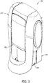
- Figures 2 and 3 are various views of the bottle 102 of the dispenser assembly 100 shown in Figure 1 . More particularly, Figure 2 is a perspective view of the bottle 102, and Figure 3 is a side view of the bottle 102.
- the bottle 102 generally includes a body portion 202, including opposing sides 204, a front 206, and a neck portion 208.
- the body portion 202 further includes a liquid chamber 210 defined therein and adapted to hold a quantity of product (e.g., a liquid, gel, or foam product).
- the body portion 202 further includes a bulge 212 defined thereon as well as a ridge 214 disposed on opposing sides 204 of the body portion 202 of the bottle 102, such that the enclosure 110 (shown in Figure 1 ) may engage the body portion 202 of the bottle 102, as described later herein.
- the bulge 212 includes a front face 216 defined generally at the front 206 of the bottle 102, oriented generally parallel with an x-z plane as defined in Figure 2 .
- the bulge 212 also includes a side face 218 that extends at least partially around the bulge 212.
- the side face 218 is oriented generally perpendicular to the front face 216 (i.e., parallel with a y-z plane).
- the side face 218 defines a depth that allows flexible movement of the enclosure 110 about the bottle 102, as will be described in more detail herein.
- the body portion 202 of the bottle 102 also includes an outwardly projecting rim 220 on opposing sides 204 of the bottle 102.
- the outwardly projecting rim 220 includes a generally elliptical edge 222, defining a concave recess 224 therein.
- the concave recess 224 is configured to enable easier handling of the bottle 102 by a user (e.g., a user installing the bottle 102 into the dispenser assembly 100 during initial installation or refill) by generally defining a grip thereon.
- the neck portion 208 of the bottle 102 includes an externally threaded portion 232 having threads 234 disposed thereon. As will be described in further detail herein, the neck portion 208 is configured to engage with a collar portion of the venting pump 104 (shown in Figure 4 ) to close the bottle 102 and contain the product therein without leakage of the product.
- the neck portion 208 generally defines an opening 236 to the bottle 102 from which product may be dispensed.
- the bottle 102 also includes a top 240 that is, as best seen in Figure 3 , substantially flat.
- the bottle 102 is configured to be converted or easily inverted, e.g., from an upside-down position (i.e., with the opening 236 facing downwards) to a right-side-up position (i.e., with the opening 236 facing upwards), such that the bottle 102 may also be used as a stand-alone bottle 102 for containing a liquid product.
- the complete dispenser assembly 100 may be installed on, for example, a wall, and a stand-alone bottle 102 may be placed on, for example, a sink vanity, with the design aesthetic of the two dispensers (i.e., the dispenser assembly 100 and the bottle 102) unified.
- the bottle 102 may also include indicia disposed thereon (not shown) for branding purposes, description of the product contained therein, or any other purpose.
- the bottle 102 may have different configurations, shapes, and sizes than those illustrated and described herein without departing from the present disclosure.
- the bottle 102 may be made of any suitable material such as, without limitation, polyethylene terephthalate (PET) or any other plastic or thermoplastic resin.
- PET polyethylene terephthalate
- the bottle 102 can be made in any desired color or colors, and may be transparent, translucent, or opaque.
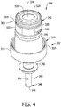
- the pump 104 includes a collar portion 302, a chamber portion 304, and a nozzle portion 306.
- the pump 104 is configured to dispense one or more of a liquid product, a gel product, and a foam product.
- the pump 104 may be used to dispense hand soaps, hand sanitizers, and lotions.
- the collar portion 302 of the venting pump 104 includes a collar 310 and an internally threaded portion 312 concentric with and disposed radially inwardly from the collar 310.
- the internally threaded portion 312 includes threads 314 disposed thereon for threaded engagement with the threads 234 of the neck portion 208 of the bottle 102 (shown in Figures 2 and 3 ).
- the threads 234, 316 are suitably disposed such that the pump 104 will close the bottle 102 to prevent leakage of the product therefrom.
- the chamber portion 304 of the venting pump 104 includes a generally cylindrical chamber 320 having a side wall 322 and an end wall 324.
- An opening 326 is defined in the end wall 324, and a passage 328 connects to the opening 326.
- the passage 328 extends axially through at least a portion of the chamber 320.
- the chamber 320 further includes vent holes 330 defined in the side wall 322 thereof.
- the nozzle portion 306 includes a first end 340 from which product (contained in bottle 102) is dispensed.
- the nozzle portion 306 also includes a second end 342 opposite the first end 340.
- the second end 342 extends into the chamber 320. More specifically, the second end 342 includes a plunger 344 configured to slidably engage with an interior surface of the chamber 320 when the pump 104 is actuated to dispense product therefrom. Put another way, the nozzle portion 306 generally defines a "piston" within the chamber portion 304.
- the nozzle portion 306 also includes a passage 346 that extends through an opening or outlet 348 in the first end 340, from the first end 340 to the second end 342, and through the plunger 344. The passage 346 of the nozzle portion 306 extends around at least a portion of the passage 328 of the chamber 320.
- the nozzle portion 306 When the pump 104 is actuated, the nozzle portion 306 is forced vertically upwards, causing the plunger 344 to slide upwards within the chamber 320.
- Product from the bottle 102 is drawn through the opening 326 in the chamber 320, through the passage 328, and, correspondingly, through the passage 346 of the nozzle portion 306.
- the product is pumped out of the outlet 348 at the first end 340 of the nozzle portion 306 in a liquid format, a gel format, or a foam format.
- the nozzle portion 306 is then drawn vertically downwards, as described further herein, thereby drawing the plunger 344 downwards to permit the chamber 320 to refill with product for the next dispensing.
- the nozzle portion 306 also includes an annular flange 350 that extends radially and horizontally from the channel 346 near the first end 340. As described further herein, the flange 350 provides a point of engagement between the pump actuator assembly 108 (shown in Figure 1 ) and the nozzle portion 306.
- the chamber portion 304 and/or the nozzle portion 306 includes additional and/or alternative components. Some such components may enable the pump 104 to dispense various formats of product, such as foam, liquid, and/or gel.
- the chamber portion 304 may include air and liquid chambers, such that a product dispensed from the dispenser assembly 100 will be in a viscous liquid state, and/or a foaming component (e.g., a mesh), such that the product is dispensed in a foam state.
- a foaming component e.g., a mesh
- the pump 104 may have different configurations, shapes, and sizes than those illustrated and described herein without departing from the present disclosure.
- the pump 104 may be made of any suitable material such as, without limitation, any plastic or thermoplastic resin.
- discrete elements of the pump 104 may be made of a different material than other elements (e.g., the chamber portion 304 and/or collar portion 302).
- the pump 104 can be made in any desired color or colors, and may be transparent, translucent, or opaque.
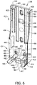
- FIG 5 is a perspective view of the dispenser assembly 100 shown in Figure 1 in an intermediate stage of assembly.
- a partial assembly 120 includes the pump 104 coupled to the bottle 102 of the dispenser assembly 100.
- the nozzle portion 306 of the pump 104 (shown in Figures 4 ) is oriented to project in an axial direction with respect to the bottle 102 to facilitate use of the dispenser assembly 100 as will be described in more detail below.
- Figures 6-8 are various views of the mounting component 106 of the dispenser assembly 100 shown in Figure 1 .
- Figure 6 is a perspective view of the mounting component 106
- Figure 7 is a front view of the mounting component 106
- Figure 8 is a back view of the mounting component 106.
- the mounting component 106 includes a back wall 402, a bottom wall 404, and two opposing side walls 406 integrally formed with the back wall 402 and bottom wall 404.
- Each side wall 406 includes an arcuate edge 408 and a front edge 410.
- the arcuate edge 408 is configured to be complementary to a shape of the body portion 202 of the bottle 102 (shown in Figures 2 and 3 ). Accordingly, when the dispenser assembly 100 is assembled, at least a portion of the body portion 202 of the bottle 102 may engage the arcuate edge 408 of at least one side wall 406 of the mounting component 106, such that the bottle 102 is supported within the dispenser assembly 100.
- the back wall 402 includes, generally, a top region 412 and a bottom region 414.
- the back wall 402 of the mounting component 106 includes at least one mounting hole 416 defined therein in at least one of the top region 412 and the bottom region 414.
- the mounting hole 416 is configured to receive a mounting element (not shown) such as, without limitation, a nail head, a screw head, or a hook, upon installation of the dispenser assembly 100, such that the mounting component 106 may be substantially fixed to a wall or other support structure (not shown).
- the back wall 402 further includes at least one mounting panel 418, which is configured to receive an adhesive element (not shown), such as, for example, a mounting tape, to further secure the mounting component 106 (and, thereby, the dispenser assembly 100) to the wall or other support structure.
- an adhesive element such as, for example, a mounting tape
- the mounting component 106 further includes two tracks 420, each track 420 generally defined by a lip 422 and a side face 424.
- the side face 424 extends from the back wall 402, and the lip 422 extends generally perpendicularly from the side face 424.
- Each track 420 is configured to receive a corresponding extension, extending from a back wall of the enclosure 110 (shown in Figure 1 ).
- Each extension is received in a corresponding track 420 to engage with at least one of the lip 422 and the side face 424, thereby releasably coupling the extension to the mounting component 106 in a "tongue and groove"-type connection, upon assembly of the dispenser assembly 100.
- the back wall 402 also includes at least one bracket 426 extending therefrom. Each bracket is configured to receive a bottom edge of a corresponding extension when the enclosure 110 engages the mounting component 106.
- the back wall 402 further includes one or more locking slots 430 defined therein.
- the back wall 402 includes a closed position locking slot 432 and an open position locking slot 434.
- the closed position locking slot 432 is positioned in the bottom region 414 of the back wall 402 and defines an opening in the back wall 402.
- the open position locking slot 434 is positioned in the top region 412 of the back wall 402 and defines another opening therein.
- each locking slot 430 is configured to receive a locking tab disposed on a back wall of the enclosure 110. When the locking tab of the enclosure 110 engages the closed position locking slot 432 in a "snap fit" configuration, the dispenser assembly 100 may be referred to as being in a closed configuration.
- the closed configuration enables use of the dispenser assembly 100 by a user (i.e., to dispense product therefrom).
- the dispenser assembly 100 may be referred to as being in an open configuration.
- the open configuration enables maintenance and manipulation (e.g., refill) of various components of the dispenser assembly 100, and in particular, the bottle 102. The transition from the closed configuration to the open configuration will be described later herein.
- each side wall 406 is oriented substantially parallel to the back wall 402 of the mounting component 106 (i.e., substantially vertically). In other embodiments, the front edge 410 may be oriented other than parallel to the back wall 402.
- Each front edge 410 includes a lip 440 extending therefrom. In the example embodiment, the lip 440 is oriented substantially perpendicular to the side walls 406. In other embodiments, each lip 440 may be oriented other than perpendicular to the side walls.
- each lip 440 is configured to engage a corresponding projection on a back wall of the pump actuator assembly 108 (shown in Figure 1 ) of the dispenser assembly 100, such that the pump actuator assembly 108 may be coupled to the mounting component 106 in a "tongue and groove"-type connection.
- each trough 442 and a locking tab 450 each project upwardly from the bottom wall 404 of the mounting component 106 (i.e., inwardly, with respect to the dispenser assembly 100 as a whole).
- Each trough 442 includes at least a front face 444 and two opposing side faces 446 defining a recess 448 therein.
- Each recess 448 is configured to receive a corresponding tab on the back wall of the bracing component 108, as will be described in further detail below.
- the locking tab 450 is disposed between the two troughs 442.
- the locking tab 450 includes a protuberance 452 configured to engage in a "snap fit" with a ridge formed on the back wall of the bracing component 108.
- the mounting component 106 further includes two support "feet" 460.
- the support feet 460 extend from each side wall 406 and from the bottom wall 404 of the mounting component.
- the support feet 460 are configured to engage with corresponding channels in the pump actuator assembly 108, as described further herein.
- the support feet 460 are at least partially arcuate, to correspond to curved corners of the pump actuator assembly 108.
- the support feet 460 may have any shape or configuration.
- the mounting component 106 may include no support feet or one "continuous" support foot that extends continuously between the side walls 406 of the mounting component 106.
- the mounting component 106 may have different configurations, shapes, and sizes than those illustrated and described herein without departing from the present disclosure.
- the mounting component 106 may be made of any suitable material such as, without limitation, acrylonitrile-butadiene-styrene (ABS), or any other plastic, composite plastic, or thermoplastic resin.
- ABS acrylonitrile-butadiene-styrene
- the mounting component 106 can be made in any desired color or colors, and may be transparent, translucent, or opaque.
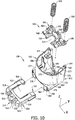
- Figures 9-13 are various views of the pump actuator assembly 108 of the dispenser assembly 100 shown in Figure 1 .
- Figure 9 is a first exploded view of a plurality of internal components 500 of the pump actuator assembly 108
- Figure 10 is a second exploded view of the pump actuator assembly 108
- Figure 11 is a bottom perspective view of the assembled pump actuator assembly 108
- Figure 12A is a first sectional view of the pump actuator assembly 108 in a ready configuration
- Figure 12B is a second sectional view of the pump actuator assembly 108 in an activated or dispensing configuration
- Figure 13 is a an expanded view of the pump actuator assembly 108 illustrating connection of the pump actuator assembly 108 with the pump 104 shown in Figure 4 .
- the pump actuator assembly 108 includes a plurality of internal components 500 that are positioned at least partially within a casing 502 (see, for example, Figures 10-13 ) to assemble the pump actuator assembly 108.
- the internal components 500 include a first actuator 504, a second actuator 506, and two springs 508.
- the first actuator 504 has a first end 510 and an opposing second end 512.
- the first end 510 is configured to extend outwardly with respect the dispenser assembly 100 (i.e., outwardly in the y direction), and the second end 512 is configured to extend inwardly with respect to the dispenser assembly 100 (i.e., inwardly in the y direction).
- the first actuator 504 includes a base 514 located generally at the first end 510 and two arms 516, 518.
- the arms 516, 218 extend from the base 514 and terminate at free ends 520 corresponding to the second end 512 of the first actuator 504.
- the two arms 516, 518 and the base 514 define a nozzle cutout 522, such that the first actuator 504 is generally U-shaped.
- Each arm 516, 518 includes a top wall 524, a side wall 528, and a rear wall 530 (so called as it corresponds to a back- or rearward direction of the dispenser assembly 100).
- a lower ramp 532 extends at an angle between the top wall 524 and the rear wall 530, defining an angled surface therebetween.
- an extension 534 extends from the side wall 528 of each arm 516, 518, and a tab 536 extends downwardly from a bottom edge 526 of the side wall 528 (i.e., downwardly in the z direction, away from the top wall 524).
- the base 514 includes two cutouts 538 defined therein, the cutouts 538 defining a projection 540 therebetween.
- the projection 540 includes two opposing flanges 542 that extend from the projection 540 into the cutouts 538.
- the base 514 only includes the projection 540 (i.e., without the cutouts 538).
- the second actuator 506 includes a first end 544 and a second end 546.
- the first end 544 includes two arms 548, 550 that extend from a base 552 at the second end 546.
- the arms 540, 550 and the base 552 define a nozzle cutout 554, such that the second actuator 506 is also generally U-shaped.
- the nozzle cutout 554 of the second actuator 506 is configured to (at least partially) align with the nozzle cutout 522 of the first actuator 504 when the pump actuator assembly 108 is assembled.
- the base 552 of the second actuator 506 includes two pegs 556 configured to extend at least partially through corresponding springs 508 therearound.
- the size of the pegs 556 generally corresponds to an inner diameter of the springs 508.
- the base 552 also includes a vertically extending tab 558.
- the tab 558 has a cutout 559 defined therein.
- the arms 548, 550 of the second actuator 506 each include a top wall 560 and a side wall 562 continuous between the arms 548, 550.
- One or more tabs 564 extend from the top wall 560 of each arm 548, 550 and from the side wall 562 into the nozzle cutout 554.
- a ledge 566 extends from the side wall 562 into the nozzle cutout 554, the ledge 566 spaced vertically from the tabs 564.
- the tabs 564 and the ledge 566 cooperate to receive the flange 350 of the nozzle portion 306 of the pump 104 (also shown in Figure 4 ) and each define a vertical "stop" limiting the vertical motion of the flange 350 with respect to the second actuator 506.
- the tabs 564 and the ledge 566 cooperate to ensure that the flange 350 (and, thereby, the nozzle portion 306) is appropriately actuated.
- the flange 350 is raised when the second actuator 506 is raised, and the flange 350 is drawn downwards when the second actuator 506 is lowered, as described further herein.
- Each arm 548, 550 includes an upper ramp 568 that extends downward from the top wall 560, defining an angled surface.
- Each arm 548, 550 further includes a pair of extension walls 570 extending outwardly therefrom, opposite the nozzle cutout 554.
- Each pair of extension walls 570 define a channel 571 therebetween.
- the casing 502 of the pump actuator assembly 108 includes a back wall 572, two side walls 574 extending generally "frontwards" therefrom, a front wall 576 extending from and arcuately connecting the side walls 574, and a bottom wall 578.
- the walls 572, 574, 576, 578 generally define a cavity 579 therein.
- the side walls 574 and the front wall 576 include a continuous top edge 573.
- the top edge 573 includes arcuate portions 575 arranged symmetrically therein. Each arcuate portion 575 is configured to be complementary to the shape of the body portion 202 of the bottle 102 (shown in Figures 2 and 3 ).
- the dispenser assembly 100 when the dispenser assembly 100 is assembled, at least a portion of the body portion 202 of the bottle 102 may engage an arcuate portion 575 of the top edge 573 of the casing 502, such that the bottle 102 is supported and braced within the dispenser assembly 100.
- each side wall 574 receives a corresponding one of the arms 516, 518 of the first actuator 504 when the pump actuator assembly 108 is assembled.
- each side wall 574 includes a pair of rails 582 extending therefrom into a corresponding base channel 580.
- Each pair of rails 582 defines a groove 583 therebetween.
- Each groove 583 is configured to receive a corresponding extension 534 on one of the arms 516, 518, to couple the arms 516, 518 to the casing 502 and ensure suitable movement of the arms 516, 518 within the base channels 580.
- the base channels 580 define a nozzle cutout 584 therebetween.
- the nozzle cutout 584 of the casing 102 is configured to (at least partially) align with the nozzle cutout 522 of the first actuator 504 and the nozzle cutout 554 of the second actuator 506 when the pump actuator assembly 108 is assembled, such that the nozzle portion 306 of the pump 104 is received the nozzle cutouts 584, 522, and 554 (as shown in Figure 13 ).
- the casing 502 includes a pair of ribs 586 extending inwards into the cavity 579 from the side walls 574 and the bottom wall 578, as well as a ridge 588 extending upwards into the cavity 579 from the bottom wall 578.
- each channel 571 receiving a corresponding one of the ribs 586, between the corresponding pair of extension walls 570.
- the ridge 588 on the casing 502 extends through an opening (not shown) in the base 552 of the second actuator 506 to seat against the tab 558 on the base 552.
- the cutout 559 in the tab receives a protuberance 589 on the ridge 588, to couple the second actuator 506 to the casing 502.
- the casing 502 further includes a pair of upper ledges 590 extending into the cavity 579 from the back wall 572 and the side walls 574.
- the upper ledges 590 are substantially parallel to the bottom wall 578.
- each upper ledge 590 has a corresponding peg 591 extending downwards from a bottom surface of the upper ledge 590.
- the springs 508 are seated on the pegs 556 of the second actuator 506 and are compressed to fit beneath the upper ledges 590, such that an upper end of the springs 508 is able to be seated over pegs 591 of the upper ledges 590. Accordingly, the springs 508 are in a constant state of compression and tension, and therefore tend to bias or urge the second actuator 506 downward, absent the presence of an opposing force.
- two springs 508 are included in the illustrated embodiment of the pump actuator assembly 108, it should be understood that a greater number of springs may be used, one spring may be used, or an alternative biasing component may be used, without departing from the scope of the disclosure.
- the pump actuator assembly 108 When the internal components 500 are installed in the casing 502, the pump actuator assembly 108 is complete (see Figures 11-13 ). As shown in Figure 12A , when the pump actuator assembly 108 is in a "ready" configuration (i.e., ready for use), the lower ramp 532 of the first actuator 504 is partially engaged with the upper ramp 568 of the second actuator 506.
- a force having a component defined in a first direction along a first axis is exerted on the first end 510 of the first actuator 504, causing the first actuator 504 to move in the first direction parallel to the first axis (e.g., along the y-axis).
- the lower ramp 532 is therefore urged against the upper ramp 568, causing the upper ramp 568 to slide against the lower ramp 532.
- the lower ramp 532 exerts a force having a component defined in a second direction along a second axis (e.g., the z-axis) on the upper ramp 568.
- the second actuator 506 travels in the second direction parallel to the second axis (e.g., along the z-axis).
- the second actuator 506 drives the flange 350 of the pump 104 along the second axis (e.g., upwards) therewith to actuate the pump 104.
- the second actuator 506 further compresses the springs 508.
- the first axis and the second axis may be perpendicular to one another (e.g., the y-axis is perpendicular to the z-axis). In alternative embodiments, the first axis and the second axis are other than perpendicular to one another.
- the second axis forms an acute angle with respect to the first axis, or the second axis forms an obtuse angle with respect to the first axis.
- the axes may form an angle between about 87 degrees and about 93 degrees relative to one another.
- the lower ramp 532 is oriented obliquely with respect to the first axis
- the upper ramp 568 is oriented obliquely with respect to the second axis.
- the lower ramp 352 may also be oriented obliquely with respect to the first axis, and/or the upper ramp 568 may be oriented obliquely with respect to the first axis.
- the spring force of the (further compressed) springs 508 is exerted in a downward vertical (z) direction, urging the second actuator 506 opposite the second direction along the second axis (e.g., downwards along the z-axis).
- the upper ramp 568 is urged against the lower ramp 532. In so doing, the upper ramp 568 exerts a force having a component defined opposite the first direction along the first axis (e.g., outwards along the y-axis) on the lower ramp 532.
- the first actuator 504 is forced opposite the first direction along the first axis (e.g., outwards along the y-axis).
- the second actuator 506 forces the flange 350 of the pump 104 downwards therewith.
- each channel 592 is generally defined by a pair of generally L-shaped projections 594 extending from the back wall 572. As described above with respect to Figures 6-8 and the discussion of the mounting component 106, each channel 592 is configured to receive a lip 440 of the mounting component 106 therein to facilitate coupling the pump actuator assembly 108 to the mounting component 106 during assembly of the dispenser assembly 100.
- the back wall 572 further includes at least one tab 596 extending therefrom.
- each tab 596 is integrally formed with and adjacent to a projection 594.
- each tab 596 is inserted into a corresponding recess 448 of a trough 442 in the mounting component 106 (shown in Figure 6 ).
- Each tab 596 engages in a friction fit with a front face 444 (shown in Figure 6 ) of a corresponding trough 442 to couple the pump actuator assembly 108 to the mounting component 106.
- the back wall 572 further includes a lip 598 defined therein.
- the lip 598 is configured to engage in a friction fit with the protuberance 452 of the locking tab 450 of the mounting component 106 (also shown in Figure 6 ).
- the lip 598 is disposed between two tabs 596.
- the pump actuator assembly 108 may have different configurations, shapes, and sizes than those illustrated and described herein without departing from the present disclosure.
- the pump actuator assembly 108 may be made of any suitable material such as, without limitation, ABS, or any other plastic, composite plastic, or thermoplastic resin.
- the pump actuator assembly 108 can be made in any desired color or colors, and may be transparent, translucent, or opaque.
- FIG 14 is a perspective view of the dispenser assembly 100 shown in Figure 1 in another intermediate stage of assembly.
- a partial assembly 122 includes the pump actuator assembly 108 coupled to the mounting component 106, as described above.
- the pump actuator assembly 108 and the mounting component 106 may be coupled together at a manufacturer location.
- the pump actuator assembly 108 and the mounting component 106 may be coupled together during installation of the dispenser assembly 100.
- the pump actuator assembly 108 and the mounting component 106 releasably couple together, whereas in another embodiment, the pump actuator assembly 108 and the mounting component 106 permanently couple together.
- the partial assembly 122 acts as a locating cradle for the partial assembly 120 (shown in Figure 5 ), including the bottle 102 and the pump 104.
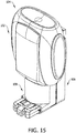
- Figure 15 is a perspective view of the dispenser assembly 100 shown in Figure 1 in another intermediate stage of assembly. More particularly, Figure 15 illustrates a partial assembly 124 including the bottle 102, the pump 104, the pump actuator assembly 108, and the mounting component 106.
- the partial assembly 124 includes the partial assembly 120 (shown in Figure 5 ) coupled to the partial assembly 122 (shown in Figure 14 ).
- Figures 16-18 are various views of the enclosure 110 of the dispenser assembly 100 shown in Figure 1 . More particularly, Figure 16 is a perspective view of the enclosure 110, Figure 17 is a side view of the enclosure 110, and Figure 18 is a bottom view of the enclosure 110.
- the enclosure 110 includes a back wall 602 integrally formed with a top portion 604, which is itself integrally formed with at least one semi-rigid rib 606.
- semi-rigid refers generally to a rigidity that allows a structure to maintain a predetermined form when not acted upon by a force, and that is flexible enough to bend without breaking when acted upon by a force.
- the enclosure 110 includes two semi-rigid ribs 606 integrally formed with and bridged by a handle portion 608.
- the handle portion 608 may be rigid or semi-rigid.
- the handle portion 608 may be other than integrally formed with the semi-rigid ribs 606 and may include additional components such as a cushioning member (e.g., for cushioning a user's palm during use of the dispenser assembly 100), a sanitizing member (e.g., an antibacterial material and/or coating disposed thereon), and/or indicia (e.g., to direct a user to press or push on the handle, rather than pull).
- the enclosure 110 is configured such that, when the dispenser assembly 100 is assembled, a user may impose a pushing force on the handle portion 608, which causes the semi-rigid ribs 606 to bend slightly.
- the handle portion 608 may be depressed (i.e., moved inwardly, with respect to the dispenser assembly 100 as a whole) without movement of the entire enclosure 110.
- the back wall 602 of the enclosure 110 remains fixed with respect to the dispenser assembly 100 during operation.
- the handle portion 608 of the enclosure 110 includes a pair of symmetrical brackets 610 integrally formed therewith, as best seen in Figure 18 .
- Each bracket 610 is configured to receive a corresponding one of the flanges 542 on the projection 540 on the first end 510 of the first actuator 504 (shown in Figures 9-11 ) when the enclosure 110 is installed first actuator 504 is thereby fixed relative to the handle portion 608 of the enclosure 110.
- the configuration of the brackets 610 about the flanges 542 ensures that the nozzle portion 306 (shown in Figure 4 ) of the pump 104 will be in a "ready" configuration (i.e., positioned vertically downwards) when the enclosure 110 is in a "ready” configuration (i.e., undepressed and ready for use); and that the nozzle portion 306 will always be depressed at the same rate as the handle portion 608 of the enclosure 110.
- operatively coupling the handle portion 608 to the first actuator 504 further ensures that the handle portion 608 will be returned to the "ready” configuration after depression thereof (during use of the dispenser assembly 100).
- the first actuator 504 is biased into a "ready” configuration by the springs 508, as described above, and will therefore urge handle portion 608 back into the "ready” configuration correspondingly.
- an additional benefit of the configuration of the brackets 610 about the flanges 542 of the first actuator 504 is that a user is substantially prevented from pulling the handle portion 608 away from the first actuator 504, preventing user frustration and confusion about the functionality of the dispenser assembly 100.
- the outlet 348 of the nozzle portion 306 may extend slightly past a bottom of the handle portion 608, such that product dispensed from the outlet 348 does not contact any part of the handle portion 608.
- the semi-rigid ribs 606 are spaced apart from each other to accommodate the bulge 212 of the bottle 102 (shown in Figures 2 and 3 ) when the dispenser assembly 100 is assembled.
- the semi-rigid ribs 606 are shaped to conform to the front 206 of the body portion 202 of the bottle 102 (also shown in Figures 2 and 3 ).
- the top portion 604 and the semi-rigid ribs 606 are defined by a generally elliptical outer edge 612 and a shoulder edge 614.
- the elliptical outer edge 612 is configured to be complementary to the generally elliptical edge 222 of the outwardly projecting rim 220 on the bottle 102 (also shown in Figures 2 and 3 ).
- the shoulder edge 614 is configured to be complementary to a shape of the ridge 214 of the bottle 102 (also shown in Figures 2 and 3 ). Accordingly, when the dispenser assembly 100 is assembled, the elliptical outer edge 612 and shoulder edge 614 of the enclosure 110 are coupled substantially against, respectively, the outwardly projecting rim 220 and ridge 214 of the bottle 102.
- top portion 604 and the semi-rigid ribs 606 are substantially flush with at least a portion of the body portion 202 of the bottle 102. Not only is the bottle 102 secured by the enclosure 110, but the result is aesthetically pleasing, as the dispenser assembly 100 has a substantially smooth surface.
- the back wall 602 of the enclosure 110 is generally defined by two opposing side edges 620.
- the side edges 620 further define a pair of symmetrical extensions 622.
- the extensions 622 are configured to be slidably inserted into the track 420 of the mounting component 106 (shown in Figures 6 and 7 ), to install the enclosure 110 into the mounting component 106 and onto the dispenser assembly 100. Accordingly, the enclosure 110 is easily removed from and inserted into the mounting component 106 for installation and subsequent maintenance (e.g., cleaning or replacement).
- Each extension 622 includes a bottom edge 624.
- each bottom edge 624 couples to a corresponding bracket 426 of the mounting component 106 (also shown in Figures 6 and 7 ) to ensure accurate placement of the enclosure 110 into the mounting component 106.
- a locking tab 626 defined on the back wall 602 of the enclosure 110 is positioned to engage in a "snap fit" with the closed position locking slot 432 of the mounting component 106 (shown in Figures 6-8 ).
- the enclosure 110 is at its lowest position with respect to the mounting component 106, and the dispenser assembly 100 is in its closed configuration.
- the locking tab 626 includes an angled protuberance 628, which enables depression of the locking tab 626 by a force directed upwards (i.e., in the z direction).
- the enclosure 110 may have different configurations, shapes, and sizes than those illustrated and described herein without departing from the present disclosure.
- the enclosure 110 may be made of any suitable material such as, without limitation, polycarbonate (PC), ABS, or any other plastic, composite plastic, or thermoplastic resin or combination thereof.
- the enclosure 110 can be made in any desired color or colors, and may be transparent, translucent, or opaque.
- FIG 19 is an exploded view of the dispenser assembly 100 shown in Figure 1 .
- the dashed lines represent relative movement of the various components to assemble the dispenser assembly 100.
- the pump 104 is coupled to the bottle 102 to form the partial assembly 120 (shown in Figure 5 ).
- the pump actuator assembly 108 is coupled to the mounting component 106 to form the partial assembly 122 (shown in Figure 14 ).
- the partial assembly 120 is coupled to the partial assembly 122, forming the partial assembly 124 (shown in Figure 15 ).
- the enclosure 110 is coupled to the partial assembly 124 (in particular, to the mounting component 106). It should be understood that the order described above is described for example only, and that the dispenser assembly 100 can be assembled in any other suitable order to form the dispenser assembly 100 described herein.
- Figures 20 and 21 illustrate the transition of the dispenser assembly 100 from the closed configuration to the open configuration. More particularly, Figure 20 is a perspective view of the dispenser assembly 100 shown in Figure 1 in the closed configuration, and Figure 21 is a perspective view of the dispenser assembly 100 shown in Figure 1 in the open configuration.
- the locking tab 626 of the enclosure 110 (shown in Figures 16-18 ) is engaged with the closed position locking slot 432 of the mounting component 106 (shown in Figures 6-8 ).
- the enclosure 110 is decoupled from the mounting component 106 and released from the closed configuration.
- the enclosure 110 may be slidably moved upwards with respect to the mounting component 106.
- the extensions 622 of the enclosure 110 may slide within the track 420 of the mounting component 106 (shown in Figure 6 and 7 ) until the locking tab 626 engages with the open position locking slot 434 (shown in Figures 6-8 ) to transition the dispenser assembly 100 from the closed to the open configuration.
- the bottle 102 is easily accessible for removal and/or refill (and/or other maintenance of the dispenser assembly 100). Accordingly, refill of the dispenser assembly 100 is simplified. The entire dispenser assembly 100 need not be removed from the wall; refill and/or other maintenance may be performed by only adjusting the enclosure 110. Further, no additional parts (e.g., keys) are needed to refill the dispenser assembly 100.
- a user may return the dispenser assembly 100 to the closed configuration by applying pressure to the top portion 604 of the enclosure 110 (shown in Figures 16-18 ).
- This causes a bottom edge of the open position locking slot 434 to exert an upward force on the angled protuberance 628 of the locking tab 626 (shown in Figures 16 and 17 ), forcing the locking tab 626 inwards and out of engagement with the open position locking slot 434.
- the enclosure 110 can be moved downwards until the locking tab 626 engages with the closed position locking slot 432, (reversibly) locking the dispenser assembly 100 in the closed configuration.
- this inward motion of the first actuator 504 causes “inward” and “upward” motion of the second actuator 506 in the second direction along the second axis.
- Upward motion of the second actuator 506 causes upward motion of the flange 350 of the nozzle portion 306, thereby activating the dispensing functionality of the pump 104 as described above.
- depressing the handle portion 608 about % inch causes about 0.8 mL of product to be dispensed from the outlet 358 of the nozzle portion 306 into the hand of the user.
- the amount of product dispensed may be greater than or less than 0.8 mL.
- more or less than 0.8mL may dispensed in various formats of product, such as a liquid, gel, or foam product. The user need not contact any part of the nozzle portion 306 in order to receive dispensed product.
- a user may exert the pushing force on the handle portion 608 using means other than the palm of his or her hand.
- a user may use his or her fingers, fist, elbow, or forearm to dispense a product into a receptacle (e.g., a handle, a bottle, or any other receptacle).
- a receptacle e.g., a handle, a bottle, or any other receptacle.
- the embodiments disclosed herein may be easier to use than traditional dispensers for people with various disabilities and may be compliant with the Americans with Disabilities Act (ADA).
- ADA Americans with Disabilities Act
- the examples described herein are not meant to limit use of the dispenser assembly 100 to a particular embodiment or product.
- the disclosure provides a minimal dispenser assembly that requires less plastic casing and that features an easily replaceable, invertible bottle.
- the bottle may be used in an upright or inverted orientation.
- the minimal design reduces maintenance and is thereby relatively cost efficient as compared to at least some known designs.
- the disclosure provides a dispenser assembly with a nozzle that enables the use of multiple formats of product to be dispensed, including liquids, foams, and gels, providing flexibility in its use.
- Embodiments of the disclosure may provide advantages such as, for example, a minimal design that reduces manufacture, maintenance, and/or replacement costs of dispenser assemblies.
- the minimal design described herein also enhances the aesthetic appeal of the dispenser assembly 100.
- the materials used in the manufacture of the bottle 102 may be more environmentally friendly than at least some known bottles.
- the dispenser assembly 100 described herein provides full visibility of the bottle (e.g., bottle 102), eliminating the need for a sight window for determination of when a refill is needed.
- the mounting component 106 is easily installed and allows for simple installation of the entire dispenser assembly 100.
- the dispenser assembly 100 has a low profile such that it can be installed in a variety of locations, promoting ease of access and hand hygiene compliance.
- refill bottles e.g., a bottle 102
- the design of the dispenser assembly 100 enables the use of a wide variety of refill products in a variety of formats (e.g., liquid, foam, gel) without the need to exchange any components of the dispenser assembly 100 other than the bottle 102.
- Personalization of the dispenser assembly 100 is also simple, in that replacement/exchange of the enclosure 110 (e.g., an enclosure 110 of a new color or pattern) is easily performed without need to replace/exchange any other components of the dispenser assembly 100.
Landscapes
- Health & Medical Sciences (AREA)
- Public Health (AREA)
- Containers And Packaging Bodies Having A Special Means To Remove Contents (AREA)
- Closures For Containers (AREA)
- Devices For Dispensing Beverages (AREA)
Applications Claiming Priority (1)
| Application Number | Priority Date | Filing Date | Title |
|---|---|---|---|
| US15/253,022 US9700181B1 (en) | 2016-08-31 | 2016-08-31 | Dispenser assembly including enclosure with handle |
Publications (2)
| Publication Number | Publication Date |
|---|---|
| EP3290124A2 true EP3290124A2 (fr) | 2018-03-07 |
| EP3290124A3 EP3290124A3 (fr) | 2018-05-30 |
Family
ID=59257853
Family Applications (1)
| Application Number | Title | Priority Date | Filing Date |
|---|---|---|---|
| EP17188564.3A Withdrawn EP3290124A3 (fr) | 2016-08-31 | 2017-08-30 | Ensemble de distribution |
Country Status (4)
| Country | Link |
|---|---|
| US (1) | US9700181B1 (fr) |
| EP (1) | EP3290124A3 (fr) |
| CA (1) | CA2969578C (fr) |
| MX (1) | MX393778B (fr) |
Families Citing this family (12)
| Publication number | Priority date | Publication date | Assignee | Title |
|---|---|---|---|---|
| US10022023B2 (en) * | 2015-04-07 | 2018-07-17 | Vi-Jon, Inc. | Dispenser assembly |
| CA3066420C (fr) * | 2015-07-23 | 2023-03-07 | William J. Schalitz | Distributeur de savon jetable |
| US10034585B2 (en) * | 2015-08-05 | 2018-07-31 | Gojo Industries, Inc. | Pumps with restrictor-based lost motion |
| US10653277B2 (en) * | 2016-12-14 | 2020-05-19 | Gojo Industries, Inc. | Manual dispensers requiring lower force to operate |
| EP3960049A1 (fr) | 2020-08-27 | 2022-03-02 | Huonker GmbH | Dispositif de distribution d'un fluide, en particulier d'un fluide de nettoyage, d'entretien ou de désinfectant pour les mains, ainsi que système de surveillance d'un tel dispositif |
| US11253110B1 (en) * | 2020-10-29 | 2022-02-22 | Satellite Industries, Inc. | Dispenser for soap and sanitizer |
| US12478223B2 (en) * | 2021-06-21 | 2025-11-25 | Kimberly-Clark Worldwide, Inc. | Dispensing device with improved motor assembly |
| US11744412B2 (en) | 2021-10-07 | 2023-09-05 | Deb Ip Limited | Dispenser system |
| US12185884B2 (en) | 2021-10-07 | 2025-01-07 | Deb Ip Limited | Dispenser |
| US11744413B2 (en) | 2021-10-07 | 2023-09-05 | Deb Ip Limited | Dispenser assembly |
| MX2024005829A (es) | 2021-11-23 | 2024-05-24 | Kimberly Clark Co | Dispositivo dispensador con conjunto de motor mejorado. |
| US12484740B1 (en) * | 2023-03-15 | 2025-12-02 | Behavioral Safety Products, Llc | Wall-mountable and ligature-resistant manually-operated liquid/gel dispenser |
Family Cites Families (17)
| Publication number | Priority date | Publication date | Assignee | Title |
|---|---|---|---|---|
| US6082586A (en) | 1998-03-30 | 2000-07-04 | Deb Ip Limited | Liquid dispenser for dispensing foam |
| US6832701B2 (en) * | 2002-04-05 | 2004-12-21 | Johnsondiversey, Inc. | Self metering dispensing device |
| US7044328B1 (en) * | 2002-07-08 | 2006-05-16 | Joseph S. Kanfer | Tamper proof latch for dispensers |
| ATE385727T1 (de) * | 2005-05-03 | 2008-03-15 | Johnson Diversey Inc | Seifenspender |
| US8071933B2 (en) * | 2007-06-18 | 2011-12-06 | Gotohti.Com Inc | Photochromic optically keyed dispenser |
| CA2863738C (fr) | 2007-06-22 | 2016-04-26 | Op-Hygiene Ip Gmbh | Bride en deux pieces pour piston a pompe de distributeur a savon |
| CA2875087C (fr) | 2007-12-07 | 2016-06-07 | Op-Hygiene Ip Gmbh | Distributeur de mousse a fente inclinee |
| CA2645953A1 (fr) | 2008-12-08 | 2010-06-08 | Gotohti.Com Inc. | Bride pour piston a pompe de distributeur de liquide |
| US8113388B2 (en) | 2008-12-08 | 2012-02-14 | Heiner Ophardt | Engagement flange for removable dispenser cartridge |
| US8245877B2 (en) | 2009-07-22 | 2012-08-21 | Gotohti.Com Inc. | Dispenser with palm reader |
| CA2687879C (fr) * | 2009-12-08 | 2016-11-01 | Gotohti.Com Inc. | Piston dote d'une butee frangible |
| US8827120B2 (en) * | 2010-09-30 | 2014-09-09 | Rubbermaid Commercial Products, Llc | Dispenser with discharge quantity selector |
| CA2772507C (fr) * | 2012-03-20 | 2018-12-18 | Gotohti.Com Inc. | Pompe precontrainte adaptable |
| US8851331B2 (en) * | 2012-05-04 | 2014-10-07 | Ecolab Usa Inc. | Fluid dispensers with adjustable dosing |
| US9090380B2 (en) * | 2012-12-19 | 2015-07-28 | Silgan Plastics Llc | Container, handle attachment and method |
| US20140231460A1 (en) * | 2013-02-15 | 2014-08-21 | Ecolab Usa Inc. | Focusing location of antimicrobial additives in fluid dispensers |
| US10022023B2 (en) | 2015-04-07 | 2018-07-17 | Vi-Jon, Inc. | Dispenser assembly |
-
2016
- 2016-08-31 US US15/253,022 patent/US9700181B1/en active Active
-
2017
- 2017-06-05 CA CA2969578A patent/CA2969578C/fr active Active
- 2017-08-30 MX MX2017011109A patent/MX393778B/es unknown
- 2017-08-30 EP EP17188564.3A patent/EP3290124A3/fr not_active Withdrawn
Non-Patent Citations (1)
| Title |
|---|
| None |
Also Published As
| Publication number | Publication date |
|---|---|
| MX2017011109A (es) | 2018-09-20 |
| CA2969578C (fr) | 2025-09-02 |
| EP3290124A3 (fr) | 2018-05-30 |
| MX393778B (es) | 2025-03-24 |
| CA2969578A1 (fr) | 2018-02-28 |
| US9700181B1 (en) | 2017-07-11 |
Similar Documents
| Publication | Publication Date | Title |
|---|---|---|
| CA2969578C (fr) | Appareil distributeur | |
| US10376106B2 (en) | Dispenser assembly | |
| US8640926B2 (en) | Dispenser with flexible cover | |
| EP3731709B1 (fr) | Système distributeur | |
| US7278554B2 (en) | Hinged dispenser housing and adaptor | |
| EP1114606B1 (fr) | Kit comprenant un distributeur et une poche | |
| US5452825A (en) | Liquid dispenser for vertical wall mounting | |
| AU701426B2 (en) | Liquid soap dispenser | |
| CA2968571C (fr) | Appareil distributeur | |
| US20060043114A1 (en) | Disposable dispenser | |
| US20230210316A1 (en) | An adaptor assembly for a fluid dispensing system | |
| US8870031B2 (en) | Dispenser |
Legal Events
| Date | Code | Title | Description |
|---|---|---|---|
| PUAI | Public reference made under article 153(3) epc to a published international application that has entered the european phase |
Free format text: ORIGINAL CODE: 0009012 |
|
| STAA | Information on the status of an ep patent application or granted ep patent |
Free format text: STATUS: THE APPLICATION HAS BEEN PUBLISHED |
|
| AK | Designated contracting states |
Kind code of ref document: A2 Designated state(s): AL AT BE BG CH CY CZ DE DK EE ES FI FR GB GR HR HU IE IS IT LI LT LU LV MC MK MT NL NO PL PT RO RS SE SI SK SM TR |
|
| AX | Request for extension of the european patent |
Extension state: BA ME |
|
| PUAL | Search report despatched |
Free format text: ORIGINAL CODE: 0009013 |
|
| AK | Designated contracting states |
Kind code of ref document: A3 Designated state(s): AL AT BE BG CH CY CZ DE DK EE ES FI FR GB GR HR HU IE IS IT LI LT LU LV MC MK MT NL NO PL PT RO RS SE SI SK SM TR |
|
| AX | Request for extension of the european patent |
Extension state: BA ME |
|
| RIC1 | Information provided on ipc code assigned before grant |
Ipc: A47K 5/14 20060101ALI20180425BHEP Ipc: A47K 5/12 20060101ALI20180425BHEP Ipc: B05B 11/00 20060101AFI20180425BHEP |
|
| STAA | Information on the status of an ep patent application or granted ep patent |
Free format text: STATUS: REQUEST FOR EXAMINATION WAS MADE |
|
| 17P | Request for examination filed |
Effective date: 20181108 |
|
| RBV | Designated contracting states (corrected) |
Designated state(s): AL AT BE BG CH CY CZ DE DK EE ES FI FR GB GR HR HU IE IS IT LI LT LU LV MC MK MT NL NO PL PT RO RS SE SI SK SM TR |
|
| GRAP | Despatch of communication of intention to grant a patent |
Free format text: ORIGINAL CODE: EPIDOSNIGR1 |
|
| STAA | Information on the status of an ep patent application or granted ep patent |
Free format text: STATUS: GRANT OF PATENT IS INTENDED |
|
| RIC1 | Information provided on ipc code assigned before grant |
Ipc: A47K 5/12 20060101ALI20190111BHEP Ipc: B05B 11/00 20060101AFI20190111BHEP Ipc: A47K 5/14 20060101ALI20190111BHEP |
|
| INTG | Intention to grant announced |
Effective date: 20190214 |
|
| STAA | Information on the status of an ep patent application or granted ep patent |
Free format text: STATUS: THE APPLICATION IS DEEMED TO BE WITHDRAWN |
|
| 18D | Application deemed to be withdrawn |
Effective date: 20190625 |