EP3290380B1 - Dispositif de stabilisation de cabine d'ascenseur - Google Patents
Dispositif de stabilisation de cabine d'ascenseur Download PDFInfo
- Publication number
- EP3290380B1 EP3290380B1 EP17188478.6A EP17188478A EP3290380B1 EP 3290380 B1 EP3290380 B1 EP 3290380B1 EP 17188478 A EP17188478 A EP 17188478A EP 3290380 B1 EP3290380 B1 EP 3290380B1
- Authority
- EP
- European Patent Office
- Prior art keywords
- swing arm
- guide rail
- elevator car
- stabilization apparatus
- damper
- Prior art date
- Legal status (The legal status is an assumption and is not a legal conclusion. Google has not performed a legal analysis and makes no representation as to the accuracy of the status listed.)
- Active
Links
Images



Classifications
-
- B—PERFORMING OPERATIONS; TRANSPORTING
- B66—HOISTING; LIFTING; HAULING
- B66B—ELEVATORS; ESCALATORS OR MOVING WALKWAYS
- B66B7/00—Other common features of elevators
- B66B7/02—Guideways; Guides
- B66B7/028—Guideways; Guides with earthquake protection devices
-
- B—PERFORMING OPERATIONS; TRANSPORTING
- B66—HOISTING; LIFTING; HAULING
- B66B—ELEVATORS; ESCALATORS OR MOVING WALKWAYS
- B66B11/00—Main component parts of lifts in, or associated with, buildings or other structures
- B66B11/02—Cages, i.e. cars
- B66B11/026—Attenuation system for shocks, vibrations, imbalance, e.g. passengers on the same side
- B66B11/0293—Suspension locking or inhibiting means to avoid movement when car is stopped at a floor
-
- B—PERFORMING OPERATIONS; TRANSPORTING
- B66—HOISTING; LIFTING; HAULING
- B66B—ELEVATORS; ESCALATORS OR MOVING WALKWAYS
- B66B17/00—Hoistway equipment
- B66B17/34—Safe lift clips; Keps
-
- B—PERFORMING OPERATIONS; TRANSPORTING
- B66—HOISTING; LIFTING; HAULING
- B66B—ELEVATORS; ESCALATORS OR MOVING WALKWAYS
- B66B5/00—Applications of checking, fault-correcting, or safety devices in elevators
- B66B5/0006—Monitoring devices or performance analysers
- B66B5/0018—Devices monitoring the operating condition of the elevator system
-
- B—PERFORMING OPERATIONS; TRANSPORTING
- B66—HOISTING; LIFTING; HAULING
- B66B—ELEVATORS; ESCALATORS OR MOVING WALKWAYS
- B66B5/00—Applications of checking, fault-correcting, or safety devices in elevators
- B66B5/02—Applications of checking, fault-correcting, or safety devices in elevators responsive to abnormal operating conditions
- B66B5/16—Braking or catch devices operating between cars, cages, or skips and fixed guide elements or surfaces in hoistway or well
- B66B5/18—Braking or catch devices operating between cars, cages, or skips and fixed guide elements or surfaces in hoistway or well and applying frictional retarding forces
-
- B—PERFORMING OPERATIONS; TRANSPORTING
- B66—HOISTING; LIFTING; HAULING
- B66B—ELEVATORS; ESCALATORS OR MOVING WALKWAYS
- B66B7/00—Other common features of elevators
- B66B7/02—Guideways; Guides
- B66B7/04—Riding means, e.g. Shoes, Rollers, between car and guiding means, e.g. rails, ropes
- B66B7/041—Riding means, e.g. Shoes, Rollers, between car and guiding means, e.g. rails, ropes including active attenuation system for shocks, vibrations
-
- B—PERFORMING OPERATIONS; TRANSPORTING
- B66—HOISTING; LIFTING; HAULING
- B66B—ELEVATORS; ESCALATORS OR MOVING WALKWAYS
- B66B7/00—Other common features of elevators
- B66B7/02—Guideways; Guides
- B66B7/04—Riding means, e.g. Shoes, Rollers, between car and guiding means, e.g. rails, ropes
- B66B7/047—Shoes, sliders
-
- H—ELECTRICITY
- H01—ELECTRIC ELEMENTS
- H01H—ELECTRIC SWITCHES; RELAYS; SELECTORS; EMERGENCY PROTECTIVE DEVICES
- H01H3/00—Mechanisms for operating contacts
- H01H3/02—Operating parts, i.e. for operating driving mechanism by a mechanical force external to the switch
- H01H3/16—Operating parts, i.e. for operating driving mechanism by a mechanical force external to the switch adapted for actuation at a limit or other predetermined position in the path of a body, the relative movement of switch and body being primarily for a purpose other than the actuation of the switch, e.g. for a door switch, a limit switch, a floor-levelling switch of a lift
-
- H—ELECTRICITY
- H01—ELECTRIC ELEMENTS
- H01H—ELECTRIC SWITCHES; RELAYS; SELECTORS; EMERGENCY PROTECTIVE DEVICES
- H01H2231/00—Applications
- H01H2231/03—Elevator
Definitions
- the present invention belongs to the field of elevator technologies, and relates to a stabilization apparatus of an elevator car and an elevator system using the stabilization apparatus.
- An elevator car of an elevator system is dragged or hung by a dragging medium such as a steel wire or a steel belt. Especially, when the elevator car stops at a floor position to load/unload passengers or articles, the elevator car is hung by the steel wire or steel belt, so as to relatively stop in a shaft, thus facilitating loading or unloading.
- a dragging medium such as a steel wire or a steel belt.
- the dragging medium such as the steel wire or steel belt is somewhat flexible.
- a great change in the weight of the elevator car during loading or unloading may easily cause vertical vibration of the elevator car, especially when the steel wire or steel belt is long.
- the elevator car is stopped unstably with respect to a floor position due to this vibration, thus causing poor passenger experience.
- US2011/0120809A1 discloses a collision brake for two elevator bodies which move independently of one another, comprising a first locking mechanism.
- CN205397800U discloses an elevator car stabilizing means.
- the present invention provides the following technical solutions to at least solve the above problems.
- a stabilization apparatus of an elevator car including:
- an elevator system including a steel belt, an elevator car, and a guide rail, and further including a stabilization apparatus provided in the above first aspect.
- a direction of a guide rail corresponding to an elevator is defined as a Z direction
- a direction where an initial position of a swing arm of a stabilization apparatus of an elevator car locates is defined as an X direction
- a direction perpendicular to the X direction and the Z direction is defined as a Y direction.
- orientation terms “upper” and “lower” are defined based on the Z direction
- direction terms “left” and “right” are defined based on the X direction
- direction terms “front” and “rear” are defined based on the Y direction.
- these directional terms are relative concepts, and they are used for relative descriptions and clarification and can be changed correspondingly according to changes in the orientation to which the stabilization apparatus is mounted.
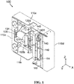
- a stabilization apparatus 100 of an elevator car according to a first embodiment of the present invention is exemplified below in detail with reference to FIG. 1 to FIG. 8 .
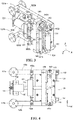
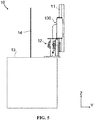
- the stabilization apparatus 100 is mounted on an elevator car 13. Specifically, as shown in FIG. 5 and FIG. 6 , the stabilization apparatus 100 is mounted on a guide shoe 12 of the elevator car 13.
- the stabilization apparatus 100 may be mounted on an upper guide shoe or a lower guide shoe, or may be mounted on the upper guide shoe and the lower guide shoe simultaneously.
- the mounting may be selected according to a principle of not affecting normal running of the elevator car 13 in a shaft.
- the stabilization apparatus 100 may even be mounted on a component of the elevator car 13 other than the guide shoe 12.
- the major function of the stabilization apparatus 100 according to the embodiment of the present invention is reducing the vertical vibration of the elevator car 13 in the Z direction when the elevator car 13 stops at a landing of a floor (for example, when a floor-door of the landing is opened).
- the stabilization apparatus 100 includes a base 110.
- the base 110 is fixedly mounted relative to the elevator car 13, for example, fixedly mounted on a guide shoe 12 of the elevator car 13.
- the base 110 may substantially be plate shaped.
- An upper edge of the plate is bent substantially perpendicularly towards the Y direction to form a base upper flange 110a
- a lower edge of the plate is bent substantially perpendicularly towards the Y direction to form a base lower flange 110b
- a left edge of the plate is bent substantially perpendicularly towards the Y direction and then bent substantially perpendicularly towards the X direction to form a base left flange 110c
- a right end cover 110d is detachably mounted at the right of the base 110.
- a semi-closed space is formed by enclosure of the base upper flange 110a, the base lower flange 110b, the base left flange 110c, and the right end cover 110d, to accommodate an internal structure of the stabilization apparatus 100 as shown in FIG. 3 .
- Notches for accommodating a guide rail 11 may be formed on the base upper flange 110a and the base lower flange 110b respectively.
- the internal structure of the stabilization apparatus 100 is provided with an upper swing arm 120a and a lower swing arm 120b.
- the upper swing arm 120a and the lower swing arm 120b are disposed substantially parallel to each other, wherein a left end of the upper swing arm 120a is pivotably fixed on the base 110.
- the upper swing arm 120a is fixed on the base 110 via an upper swing arm pivot shaft 121a provided in the Y direction.
- the upper swing arm 120a may substantially rotate or swing about the upper swing arm pivot shaft 121a on a YZ plane, and a position point of the upper swing arm pivot shaft 121a on the upper swing arm 120a is a pivot point at a left end of the upper swing arm 120a.
- the lower swing arm 120b is fixed on the base 110 via a lower swing arm pivot shaft 121b provided in the Y direction.
- the lower swing arm 120b may substantially rotate or swing about the lower swing arm pivot shaft 121b on the YZ plane, and a position point of the lower swing arm pivot shaft 121b on the lower swing arm 120b is a pivot point at a left end of the lower swing arm 120b.
- both ends of the upper swing arm pivot shaft 121a and the lower swing arm pivot shaft 121b may be fixed to the base 110 and the base left flange 110c respectively.
- the internal structure of the stabilization apparatus 100 is provided with a guide rail friction member capable of generating, with the guide rail 11, a frictional force for keeping static with respect to the guide rail 11, and the guide rail friction member has a first connecting shaft 1431 and a second connecting shaft 1411 for being connected to the upper swing arm 120a and the lower swing arm 120b respectively.
- the guide rail friction member is adsorbed on the guide rail 11 by using an electromagnet to generate a frictional force, and specifically includes an adsorption electromagnet 140 and a scissor-shaped linkage mechanism.
- the adsorption electromagnet 140 is fixed at one side, close to the guide rail 11, of the scissor-shaped linkage mechanism.
- the adsorption electromagnet 140 may generate an adsorption force on the guide rail 11 after being powered on or electrified, thereby generating the frictional force between surfaces of the adsorption electromagnet 140 and the guide rail 11.
- the specific type of the adsorption electromagnet 140 is not limited.
- a maximum static frictional force between the adsorption electromagnet 140 and the guide rail 11 may be controlled by setting a frictional coefficient of an adsorption plane of the adsorption electromagnet 140 and/or the magnitude of an adsorption force that can be generated by the adsorption electromagnet 140, or the like, that is, a predetermined maximum static frictional force is formed.
- the scissor-shaped linkage mechanism is formed a first connecting rod 141 and a second connecting rod 143 crossing each other.
- the first connecting rod 141 and the second connecting rod 143 are pivotally connected through a central pin 142.
- One end of the first connecting rod 141 is pivotably connected to an upper portion of the adsorption electromagnet 140, and the other end of the first connecting rod 141 is connected to the lower swing arm 120b via the second connecting shaft 1411.
- One end of the second connecting rod 143 is pivotably connected to a lower portion of the adsorption electromagnet 140, and the other end of the second connecting rod 143 is connected to the upper swing arm 120a via the first connecting shaft 1431.
- the central pin 142 passes through pin holes in the middle of the first connecting rod 141 and the second connecting rod 143.
- the lengths of the first connecting rod 141 and the second connecting rod 143 are set (for example, they are set to have the same length) such that the adsorption plane of the adsorption electromagnet 140 fixed on the scissor-shaped linkage mechanism is basically parallel to the guide rail 11.
- the scissor-shaped linkage mechanism may push the adsorption electromagnet 140 to approach or contact with the surface of the guide rail 11.
- the scissor-shaped linkage mechanism may push the adsorption electromagnet 140 away from the surface of the guide rail 11 to return to an initial position.
- the adsorption electromagnet 140 may be kept to move in the X direction, and it is unnecessary to set a guiding apparatus for the movement of the adsorption electromagnet 140 in the X direction.
- the structure is simple and the operation is convenient.
- the scissor-shaped linkage mechanism may provide redundant rotation at a fine tuning angle on an XZ plane for the adsorption electromagnet 140, such that the adsorption electromagnet 140 can be completely attached to and contact with the surface of the guide rail 11 when applying an adsorption force.
- the pin hole in the first connecting rod 141 or the second connecting rod 143 is set to a kidney shaped hole; this may increase the redundant rotation at the fine tuning angle.
- the pivot point at the left end of the upper swing arm 120a (that is, the position corresponding to the upper swing arm pivot shaft 121a), the pivot point at the left end of the lower swing arm (that is, the position corresponding to the upper swing arm pivot shaft 121b), a connecting point of the first connecting shaft 1431 with the upper swing arm 120a, and a connecting point of the second connecting shaft 1411 with the lower swing arm 120b substantially form four angular points of a parallelogram. That is, the upper swing arm 120a, the lower swing arm 120b, and the guide rail friction member limit each other to substantially form a parallelogram.
- the shape of the parallelogram changes when the upper swing arm 120a and the lower swing arm 120b swing vertically along with the elevator car 13; however, side lengths thereof are not changed.
- the stabilization apparatus 100 is in a non-working state, the adsorption electromagnet 140 is away from the surface of the guide rail 11.
- the parallelogram is substantially a rectangle.
- the upper swing arm 120a, the lower swing arm 120b, and the adsorption electromagnet 140 are correspondingly located at initial positions thereof.
- the internal structure of the stabilization apparatus 100 is further provided with a damper.
- An upper end of the damper is connected to a right end of the upper swing arm 120a, and a lower end thereof is pivotably fixed with respect to the base 110.
- the damper includes a hydraulic buffer 150 and a vertical piston rod 151.
- An upper end of the vertical piston rod 151 is pivotably connected to the right end of the upper swing arm 120a via a piston rod pivot shaft 152.
- a hydraulic buffer bearing seat 153 is disposed under the hydraulic buffer 150, and is disposed fixedly with respect to the base 110.
- a lower end of the hydraulic buffer 150 is pivotably fixed to the hydraulic buffer bearing seat 153 via a hydraulic buffer pivot shaft 154. In this way, the damper can rotate about the hydraulic buffer pivot shaft 154 in the XZ plane, and definitely can rotate about the hydraulic buffer pivot shaft 152 simultaneously.
- the hydraulic buffer 150 may include a structure such as an oil cylinder.
- the hydraulic buffer 150 will also synchronously move vertically while the base 110 moves vertically along with the elevator car 13.
- the right end of the upper swing arm 120a will also swing vertically while the upper swing arm 120a swings with the first connecting shaft 1431 as a swinging pivot, thus driving the vertical piston rod 151 to move vertically. Therefore, the vertical piston rod 151 can perform piston movement with respect to the hydraulic buffer 150.
- a counter-acting force will be generated to prevent it from moving away.
- a counter-acting force will be generated to prevent it from moving closer.
- the damper in the embodiment specifically disclosed above has characteristics of a single-rod bidirectional damper.
- the damper in the above embodiment is deployed at the right end of the upper swing arm 120a. Therefore, the upper swing arm pivot shaft 121a and the lower swing arm pivot shaft 121b are located at the left side of the guide rail 11, and the damper and the guide rail friction member are both located at the right side of the guide rail (referring to FIG. 7 ).
- the left end of the upper swing arm 120a is located relatively at the left side of the guide rail 11
- the right end of the upper swing arm 120b is located relatively at the right side of the guide rail 11
- the damper is disposed at the right end of the upper swing arm 120b
- the first connecting shaft 1431 corresponding to the guide rail friction member is also located relatively at the right side of the guide rail 11 on the upper swing arm 120a.
- the parallelogram where the upper swing arm 120a locates can swing vertically as a whole with the first connecting shaft 1431 as a swing pivot.
- the magnitude of displacement of the piston rod pivot shaft 152 (that is, the vertical piston rod 151) may also be determined according to the magnitude of displacement (caused by the swing) of the upper swing arm pivot shaft 121a in the Z direction.
- the ratio R may be determined according to a stroke range requirement of the vertical piston rod 151 relative to the hydraulic buffer 150.
- the ratio R of the distance between the piston rod pivot shaft 152 and the swing pivot to the distance between the upper swing arm pivot shaft 121a (that is, the pivot point at the left end of the upper swing arm 120a) and the swing pivot is less than or equal to 1/2.
- the stroke range requirement of the vertical piston rod 151 relative to the hydraulic buffer 150 is relatively small, thus being conducive to reducing the cost of the damper.
- the ratio R is set to be less than or equal to, for example, 1/5.
- the first connecting shaft 1431 is disposed on the upper swing arm 120a near the right end of the upper swing arm 120a, and the distance between the piston rod pivot shaft 152 and the swing pivot is relatively small.
- the base 110 moves downward by a distance L as an example
- the left ends of the upper swing arm 120a and the lower swing arm 120b also swing downward by the distance L
- the hydraulic buffer 150 also moves downward by the distance L along with the base 110.
- a distance by which the piston rod pivot shaft 152 swings upward is L*R. Therefore, a movement stroke of the vertical piston rod 151 with respect to the hydraulic buffer 150 is (L+L*R). Therefore, the movement stroke of the vertical piston rod 151 with respect to the hydraulic buffer 150 is one time or more of the movement distance L of the base 110.
- the first connecting shaft 1431 on the upper swing arm 120a is closer to the right end of the upper swing arm 120a, the movement stroke is closer to one time of the movement distance L.
- the internal structure of the stabilization apparatus 100 is further provided with a horizontal pushing mechanism for driving the scissor-shaped linkage mechanism to push the adsorption electromagnet 140 to approach the guide rail 11.
- the horizontal pushing mechanism mainly includes a horizontal-push solenoid coil 130, a horizontal piston rod 134, and a horizontal-push connecting rod 133 as shown in the drawing.
- the horizontal piston rod 134 may be horizontally driven to move with respect to the horizontal-push solenoid coil 130 towards the negative X direction.
- the horizontal-push solenoid coil 130 can provide power for pushing the adsorption electromagnet 140 to approach the guide rail 11.
- the horizontal-push solenoid coil 130 may be horizontally fixed on the base 110 via, for example, a fixing bracket 132, and is also relatively located at the left side of the guide rail 11, that is, at the same side as the left end of the upper swing arm 120a.
- the horizontal-push connecting rod 133 crosses the guide rail 11 and having a right end connected to the scissor-shaped linkage mechanism, specifically connected to the central pin 142.
- the horizontal-push connecting rod 133 acts on the central pin 142, and may drive the central pin 142 to move towards the negative X direction.
- the scissor-shaped linkage mechanism is opened from the initial position, so that the adsorption electromagnet 140 is pushed by the scissor-shaped linkage mechanism to approach the guide rail 11.
- the horizontal-push solenoid coil 130 may be enabled to work after being powered on or electrified.
- the specific structure and type of the horizontal-push solenoid coil 130 are not limited.
- control over the horizontal-push solenoid coil 130 may be implemented by using a controller (not shown in the drawing).
- the controller controls the horizontal-push solenoid coil 130 to be electrified, to push the adsorption electromagnet 140 to approach the guide rail 11.
- the controller controls the horizontal-push solenoid coil 130 to be powered off.
- the adsorption electromagnet 140 may also be controlled by the controller.
- the adsorption electromagnet 140 is controlled to be powered on or electrified while the horizontal-push solenoid coil 130 is powered off.
- the adsorption electromagnet 140 generates a large adsorption force, and fully contacts with the guide rail 11 to be able to generate the maximum static frictional force of a predetermined magnitude.
- the control process may be implemented automatically, and is simple and convenient.
- the adsorption electromagnet 140 first approaches and then adsorbs, so that the impact sound generated by the adsorption electromagnet 140 and the guide rail 11 during adsorption is small.
- the horizontal-push solenoid coil 130 does not need maintain electrified for a long time, and therefore, less heat is generated by the horizontal-push solenoid coil 130, avoiding the problem of overheat.
- the horizontal pushing mechanism further includes a return spring (not shown in the drawing) and a return board 131.
- the return board 131 is fixedly disposed at the outermost end (that is, the left most end) of the horizontal piston rod 134, and two ends of the return spring are fixed to the return board 131 and the horizontal-push solenoid coil 130 respectively.
- the horizontal-push connecting rod 133 is driven by the horizontal piston rod 134 to move towards the negative X direction (for example, when the horizontal-push solenoid coil 130 is electrified)
- the return board 131 is also pushed by the horizontal piston rod 134 to move towards the negative X direction.
- the distance between the return board 131 and the horizontal-push solenoid coil 130 is increased, and one or more return springs can generate increasingly larger tensile forces.
- the tensile force generated by the return spring will push the horizontal piston rod 134 and the horizontal-push connecting rod 133 to move together towards the positive X direction.
- the horizontal piston rod 134 and the horizontal-push connecting rod 133 can return to initial positions, and the adsorption electromagnet 140 is also pushed to return to the initial position as shown in FIG. 1 and FIG. 3 .
- the stabilization apparatus 100 will not interfere with the guide rail 11.
- the adsorption electromagnet 140 will not be stuck with the guide rail 11 when the elevator car 13 runs normally in the shaft. Meanwhile, preparation is made for the next work of the horizontal pushing mechanism.
- the horizontal pushing mechanism is not limited to the apparatus driven by the solenoid coil as shown in the above embodiment, and may also be other types of driving apparatuses that provide horizontal drive, such as a small-sized motor.
- the internal structure of the stabilization apparatus 100 is further provided with a reset component for enabling the upper swing arm 120a, the lower swing arm 120b, and the damper to be reset.
- the reset component specifically includes a reset rod 160, an upper reset spring 164a (not shown in FIG. 1 and FIG. 3 , referring to FIG. 8 ) disposed at an upper section of the reset rod 160, a lower reset spring 164b (not shown in FIG. 1 and FIG. 3 , referring to FIG. 8 ) disposed at a lower section of the reset rod 160, and a reset rod supporting seat 161.
- the reset rod supporting seat 161 is fixed on the base 110 and swings vertically in the Z direction along with the elevator car 13.
- the upper end of the reset rod 160 is connected to the upper swing arm 120b via the pivot shaft 162a, and the reset rod 160 can rotate with respect to the upper swing arm 120a about the pivot shaft 162a.
- the lower end of the reset rod 160 is connected to the lower swing arm 120b via a pivot shaft 162b, and the reset rod 160 can rotate with respect to the lower swing arm 120b about the pivot shaft 162b.
- the middle part of the reset rod 160 is provided with a limiting sleeve 163 capable of sliding vertically, and the limiting sleeve 163 is fixed on the reset rod supporting seat 161.
- the pivot point at the left end of the upper swing arm 120a (that is, the position point corresponding to the upper swing arm pivot shaft 121a), the pivot point at the left end of the lower swing arm 120b (that is, the position point corresponding to the lower swing arm pivot shaft 121b), the connecting points of the reset rod 160 with the upper swing arm 121a and the lower swing arm 121b (that is, the position point corresponding to the pivot shaft 162a and the position point corresponding to the pivot shaft 162b) substantially form four angular points of a parallelogram.
- the parallelogram In an initial state (that is, when the stabilization apparatus 100 is in the non-working state), the parallelogram is a rectangle.
- the pivot shaft 162a may be disposed in the middle between the pivot point at the left end of the upper swing arm 120a and the first connecting shaft 1431.
- the pivot shaft 162b may be disposed in the middle between the pivot point at the left end of the lower swing arm 120b and the second connecting shaft 1411.
- the pivot shaft 162a may be disposed at a midpoint position between the pivot point at the left end of the upper swing arm 120a and the first connecting shaft 1431
- the pivot shaft 162b may be disposed at a midpoint position between the pivot point at the left end of the lower swing arm 120b and the second connecting shaft 1411.
- the stabilization apparatus 100 exemplified above can enable the upper swing arm 120a, the lower swing arm 120b, and the damper to tend to reset, and specific principles are as follows: By taking that the base 110 moves downward by the distance L as an example, the left ends of the upper swing arm 120a and the lower swing arm 120b also swing downward by the distance L, and the reset rod supporting seat 161 and the limiting sleeve 163 also swing downward by the distance L. Based on the level principle, the distance by which the pivot shaft 162b swings downward is less than L. Therefore, the lower reset spring 164b is compressed.
- the lower reset spring 164b can generate a counter-acting force to push the lower swing arm 120b, thereby driving the upper swing arm 120a and the damper together to return to the initial positions as shown in FIG. 1 and FIG. 3 with respect to the base 110, thus preparing for the next work of the stabilization apparatus 100.
- FIG. 5 and FIG. 7 The specific mounting manner of the stabilization apparatus 100 in the above embodiment is as shown in FIG. 5 and FIG. 7 , wherein a mounting manner of one stabilization apparatus 100 in the elevator car 13 with respect to the guide rail 11 is shown, and a schematic partial structural diagram of the elevator system 10 according to an embodiment of the present invention is also shown.
- multiple stabilization apparatuses 100 may be mounted on the elevator car 13 in the same manner.
- one or more stabilization apparatuses 100 are mounted corresponding to each guide rail 11.
- the stabilization apparatus 100 may be, but not limited to, fixedly mounted on the guide shoe 12 of the elevator car 13, for example, on the upper guide shoe, on the lower guide shoe, or on the upper guide shoe and the lower guide shoe simultaneously.
- the mounting may be selected according to a principle of not affecting running of the elevator car 13 in the shaft.
- the working principle of the stabilization apparatus according to the embodiment of the present invention is illustrated below with reference to FIG. 8 .
- the stabilization apparatus 100 is in the non-working state, that is, in an initial state, and the damper, the guide rail friction member, the horizontal pushing mechanism, and the like are located at initial positions. At this time, the stabilization apparatus 100 does not affect the guide rail 11, and the elevator car 13 can move freely along the guide rail 11 under the control of an elevator controller.
- the controller of the stabilization apparatus 100 when the elevator car 13 stops at a landing, and when the floor-door opens or before the floor-door opens, the controller of the stabilization apparatus 100 enables the horizontal-push solenoid coil 130 to be powered on, and the adsorption electromagnet 140 approaches the surface of the guide rail 11. At the same time, the controller of the stabilization apparatus 100 enables the adsorption electromagnet 140 to be powered on, and the adsorption electromagnet 140 of the guide rail friction member is adsorbed and fixed on the guide rail 11.
- the static frictional force generated by the adsorption electromagnet 140 and the guide rail 11 fixes the adsorption electromagnet 140 with respect to the guide rail 11, and therefore, the internal structure of the parallelogram architecture of the stabilization apparatus 100 will swing with the first connecting shaft 1431 as a swing pivot.
- the upper swing arm 120a and the lower swing arm 120b also swing downward by the distance L (as shown by the arrow at the right of FIG. 8(c) ), and the lower reset spring 164b on the reset rod 160 also swings downward by a distance less than L (as shown by the arrow in the middle of FIG. 8(c) ) and is compressed by the reset rod supporting seat 161.
- the vertical piston rod 151 swings upward by a distance, and the hydraulic buffer 150 also moves downward by a displacement L (as shown by the arrow at the left of FIG. 8(c) ). Therefore, the oil cylinder of the hydraulic buffer 150 can absorb at least part of the energy that enables the elevator car 13 to move downward, and can prevent the upper swing arm 120a and lower swing arm 120b from swinging downward. Therefore, the stabilization apparatus 100 can eliminate or alleviate the vibration of the elevator car 13 in the vertical direction.
- the elevator car 13 stops stably at a landing to provide desirable passenger experiences.
- a predetermined maximum static frictional force that can be generated when the adsorption electromagnet 140 is adsorbing the guide rail 11 may be set, in order to prevent the damper from being beyond its limit working condition during working, for example, to prevent the stroke of the vertical piston rod 151 with respect to the hydraulic buffer 150 from exceeding its limit stroke. Therefore, when the frictional force generated by the adsorption electromagnet 140 and the guide rail 11 equals to the predetermined maximum static frictional force, the damper works basically in the limit working condition, for example, the vertical piston rod 151 is substantially located in a limit up stroke or a limit down stroke.
- the predetermined maximum static frictional force will not be able to fix the elevator car 13 with respect to the guide rail 11 if passengers and/or articles loaded on or unloaded from the elevator car 13 are over-weighted, that is, an acting force generated by the elevator car 13 and applied to the base 110 is greater than the predetermined maximum static frictional force.
- the adsorption electromagnet 140 will slide with respect to the guide rail 11, and the vertical piston rod 151 will not exceed the limit up stroke or the limit down stroke, thereby preventing the damper from working beyond its limit working condition and thus protecting it from damage.
- the predetermined maximum static frictional force may be configured by selectively setting the material of the adsorption electromagnet 140, the frictional coefficient and/or magnitude of adsorption force of the surface of the adsorption electromagnet 140, and the like.
- the stabilization apparatus 100 is further provided with an upper limit switch 170a and a lower limit switch 170b (as shown in FIG. 2 ), to implement abrasion detection of the adsorption electromagnet 140 with respect to the guide rail 11 and instruct replacement of the adsorption electromagnet 140.
- the upper limit switch 170a may be, but not limited to, mounted above the right end of the upper swing arm 120a
- the lower limit switch 170b may be, but not limited to, mounted below the right end of the lower swing arm 120b.
- positions of the lower limit switch 170b and the upper limit switch 170a on the base 110 may be set respectively, such that the sliding of the adsorption electromagnet 140 with respect to the guide rail 11 can trigger the lower limit switch 170b or the upper limit switch 170a. For example, as shown in FIG.
- the piston rod 151 is substantially in a limit up stroke state, and if the adsorption electromagnet 140 and the base 110 slide downward with respect to the guide rail, one end of the upper swing arm 120a will touch and trigger the upper limit switch 170a.
- the stabilization apparatus 100 further includes a counter (not shown), which is configured to accumulate the number of times that the upper limit switch 170a and the lower limit switch 170b are triggered. The number of times correspondingly represents the number of times that the adsorption electromagnet 140 slides with respect to the guide rail 11.
- the counter is further configured to output a maintenance reminder signal for replacing the adsorption electromagnet 140, when the accumulated number of times is greater than or equal to a predetermined value.
- the magnitude of the predetermined value may be determined by experiments in advance according to specific characteristics of the adsorption electromagnet 140.
- the counter may be reset after the adsorption electromagnet 140 is replaced.
- the counter may also send a signal to a controller of the adsorption electromagnet 140 to stop the next work of the adsorption electromagnet 140, for example, not electrify the adsorption electromagnet 140. In this way, the stabilization apparatus 100 is suspended from working, thus protecting the stabilization apparatus 100.
- the "accumulation" above may start from 0, and may also be inverse accumulation from a predetermined value.
- the positions of the upper limit switch 170a and the lower limit switch 170b are set on the base 110, such that either of the upper limit switch 170a and the lower limit switch 170b will not be pressed and triggered by a corresponding component when the damper basically works below the limit working condition.
- the counter may be formed in various control processors of the elevator system 10, or may be directly integrated in the upper limit switch 170a or the lower limit switch 170b.
- the upper limit switch 170a or the lower limit switch 170b is further configured to: output a signal if being triggered when the elevator car 13 runs normally along the guide rail 11 or being triggered continuously, to indicate that the adsorption electromagnet 140 does not return to its initial position.
- the adsorption electromagnet 140 will move upward or downward relatively under the effect of the frictional force, and meanwhile drive the upper swing arm 120a and the lower swing arm 120b to swing upward or downward.
- the right end of the upper swing arm 120a/lower swing arm 120b will continuously press the upper limit switch 170a/lower limit switch 170b. In this case, it indicates that the stuck phenomenon has been detected.
- the upper limit switch 170a/lower limit switch 170b outputs a signal to the elevator controller.
- the elevator controller may control, based on the signal, the elevator car 13 to stop at the nearest landing, to prepare for a subsequent rescuing process.
- the upper limit switch 170a/lower limit switch 170b may further output a signal to a remote monitoring system of the elevator system, to remind workers by sending an alarm. Therefore, the stabilization apparatus 100 according to the embodiment of the present invention can detect the stuck phenomenon timely, being conducive to timely maintenance and avoiding deterioration of the problem.
- the upper limit switch 170a/lower limit switch 170b is not limited to be triggered via press by the upper swing arm 120a/lower swing arm 120b.
- Other components in the parallelogram architecture where the upper swing arm 120a and the lower swing arm 120b are located may be correspondingly used for triggering the upper limit switch 170a or the lower limit switch 170b.
- the upper limit switch 170a or the lower limit switch 170b is triggered by a component on the adsorption electromagnet 140. Therefore, the specific mounting position of the upper limit switch 170a/lower limit switch 170b is not limited to the above embodiment.
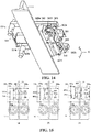
- a stabilization apparatus 300 of an elevator car according to a second embodiment of the present invention is exemplified below in detail with reference to FIG. 9 to FIG. 15 .
- the stabilization apparatus 300 is mounted on an elevator car 13.
- the manner of mounting the stabilization apparatus 300 is basically the same as the manner of mounting the stabilization apparatus 300.
- the stabilization apparatus 300 may be mounted on a guide shoe 12 of the elevator car 13.
- the stabilization apparatus 300 may be mounted on an upper guide shoe or a lower guide shoe, or may be mounted on the upper guide shoe and the lower guide shoe simultaneously.
- the mounting may be selected according to a principle of not affecting normal running of the elevator car 13 in a shaft.
- the stabilization apparatus 300 may even be mounted on a component of the elevator car 13 other than the guide shoe 12.
- the major function of the stabilization apparatus 300 according to the embodiment of the present invention is reducing the vertical vibration of the elevator car 13 in the Z direction when the elevator car 13 stops at a landing of a floor (for example, when a floor-door of the landing is opened).
- the stabilization apparatus 300 includes a base 310.
- the base 310 is fixedly mounted relative to the elevator car 13, for example, fixedly mounted on the guide shoe 12 of the elevator car 13.
- the base 310 may substantially be plate shaped.
- An upper edge of the plate is bent substantially perpendicularly towards the Y direction to form a base upper flange 310a
- a lower edge of the plate is bent substantially perpendicularly towards the Y direction to form a base lower flange 310b
- a left edge of the plate is bent substantially perpendicularly towards the Y direction and then bent substantially perpendicularly towards the X direction to form a base left flange 310c
- a right end cover 310d is detachably mounted at the right of the base 310.
- a semi-closed space is formed by enclosure of the base upper flange 310a, the base lower flange 310b, the base left flange 310c, and the right end cover 310d, to accommodate an internal structure of the stabilization apparatus 300 as shown in FIG. 11 .
- Notches for accommodating a guide rail 11 may be formed on the base upper flange 310a and the base lower flange 310b respectively.
- the internal structure of the stabilization apparatus 300 is provided with an upper swing arm 320a and a lower swing arm 320b.
- the upper swing arm 320a and the lower swing arm 320b are disposed substantially parallel to each other, wherein a left end of the upper swing arm 320a is pivotably fixed on the base 310.
- the upper swing arm 320a is fixed on the base 310 via an upper swing arm pivot shaft 321a provided in the Y direction.
- the upper swing arm 320a may substantially rotate or swing about the upper swing arm pivot shaft 321a on a YZ plane, and a position point of the upper swing arm pivot shaft 321a on the upper swing arm 320a is a pivot point at a left end of the upper swing arm 320a.
- the lower swing arm 320b is fixed on the base 310 via a lower swing arm pivot shaft 321b provided in the Y direction.
- the lower swing arm 320b may substantially rotate or swing about the lower swing arm pivot shaft 321b on the YZ plane, and a position point of the lower swing arm pivot shaft 321b on the lower swing arm 320b is a pivot point at a left end of the lower swing arm 320b.
- both ends of the upper swing arm pivot shaft 321a and the lower swing arm pivot shaft 321b may be fixed to the base 310 and the base left flange 310c respectively.
- the internal structure of the stabilization apparatus 300 is provided with a guide rail friction member capable of generating, with the guide rail 11, a frictional force for keeping static with respect to the guide rail 11, and having a first connecting shaft 3431 and a second connecting shaft 3411 for being connected to the upper swing arm 320a and the lower swing arm 320b respectively.
- the guide rail friction member is adsorbed on the guide rail 11 by using an electromagnet to generate a frictional force, and specifically includes an adsorption electromagnet 340 and a scissor-shaped linkage mechanism.
- the adsorption electromagnet 340 is fixed at one side, close to the guide rail 11, of the scissor-shaped linkage mechanism.
- the adsorption electromagnet 340 may generate an adsorption force on the guide rail 11 after being powered on or electrified, thereby generating the frictional force between surfaces of the adsorption electromagnet 340 and the guide rail 11.
- the specific type of the adsorption electromagnet 340 is not limited.
- a maximum static frictional force between the adsorption electromagnet 340 and the guide rail 11 may be controlled by setting a frictional coefficient of an adsorption plane of the adsorption electromagnet 340 and/or the magnitude of an adsorption force that can be generated by the adsorption electromagnet 340, or the like, that is, a predetermined maximum static frictional force is formed.
- the scissor-shaped linkage mechanism is formed by a first connecting rod 341 and a second connecting rod 343 crossing each other.
- the first connecting rod 341 and the second connecting rod 343 are pivotally connected through a central pin 342.
- One end of the first connecting rod 341 is pivotably connected to an upper portion of the adsorption electromagnet 340, and the other end of the first connecting rod 341 is connected to the lower swing arm 320b via the second connecting shaft 3411.
- One end of the second connecting rod 343 is pivotably connected to a lower portion of the adsorption electromagnet 340, and the other end of the second connecting rod 343 is connected to the upper swing arm 320a via the first connecting shaft 3431.
- the central pin 342 passes through pin holes in the middle of the first connecting rod 341 and the second connecting rod 343.
- the lengths of the first connecting rod 341 and the second connecting rod 343 are set (for example, they are set to have the same length) such that the adsorption plane of the adsorption electromagnet 340 fixed on the scissor-shaped linkage mechanism is basically parallel to the guide rail 11.
- the scissor-shaped linkage mechanism may push the adsorption electromagnet 340 to approach or contact with the surface of the guide rail 11.
- the scissor-shaped linkage mechanism may push the adsorption electromagnet 340 away from the surface of the guide rail 11 to return to an initial position.
- the adsorption electromagnet 340 may be kept to move in the X direction, and it is unnecessary to set a guiding apparatus for the movement of the adsorption electromagnet 340 in the X direction.
- the structure is simple and the operation is convenient.
- the scissor-shaped linkage mechanism may provide redundant rotation at a fine tuning angle on an XZ plane for the adsorption electromagnet 340, such that the adsorption electromagnet 340 can be completely attached to and contact with the surface of the guide rail 11 when applying an adsorption force.
- the pin hole in the first connecting rod 341 or the second connecting rod 343 is set to a kidney shaped hole; this may increase the redundant rotation at the fine tuning angle.
- the pivot point at the left end of the upper swing arm 320a (that is, the position corresponding to the upper swing arm pivot shaft 321a), the pivot point at the left end of the lower swing arm (that is, the position corresponding to the upper swing arm pivot shaft 321b), a connecting point of the first connecting shaft 3431 with the upper swing arm 320a, and a connecting point of the second connecting shaft 3411 with the lower swing arm 320b substantially form four angular points of a parallelogram. That is, the upper swing arm 320a, the lower swing arm 320b, and the guide rail friction member limit each other to substantially form a parallelogram.
- the shape of the parallelogram changes when the upper swing arm 320a and the lower swing arm 320b swing vertically along with the elevator car 13; however, side lengths thereof are not changed.
- the adsorption electromagnet 340 is away from the surface of the guide rail 11.
- the parallelogram is substantially a rectangle.
- the upper swing arm 320a, the lower swing arm 320b, and the adsorption electromagnet 340 are correspondingly located at initial positions thereof.
- the internal structure of the stabilization apparatus 300 is further provided with a damper.
- An upper end of the damper is pivotably connected to the upper swing arm 320a, and a lower end thereof is pivotably connected to the lower swing arm 320b.
- Connection positions of the upper end and the lower end of the damper on the upper swing arm 320a and the lower swing arm 320b are set such that the damper is located between the guide rail friction member and the upper swing arm pivot shaft 321a/lower swing arm pivot shaft 321b.
- the damper includes a hydraulic buffer 350, an upper piston rod 351a, and a lower piston rod 351b.
- An upper end of the upper piston rod 351 a is pivotably connected to the middle portion of the upper swing arm 320a via an upper piston rod pivot shaft 352a, for example, connected to a midpoint position between the pivot point at the left end of the upper swing arm 320a and the first connecting shaft 3431.
- a lower end of the lower piston rod 351b is pivotably connected to the middle portion of the lower swing arm 320b via a lower piston rod pivot shaft 352b, for example, connected to a midpoint position between the pivot point at the left end of the lower swing arm 320b and the second connecting shaft 3411.
- a hydraulic buffer bearing seat 353 is disposed corresponding to the damper, and is fixedly disposed with respect to the base 310.
- the hydraulic buffer bearing seat 353 may specifically be designed as a C-shaped bearing seat, and the hydraulic buffer 353 is enclosed by the C-shaped bearing seat.
- the hydraulic buffer 350 is supported on the base 310 via the hydraulic buffer bearing seat 353, and swings vertically along with the elevator car 13 in the Z direction.
- the damper as a whole is substantially parallel to a connecting line formed between the connecting point of the first connecting shaft 3431 with the upper swing arm 320a and the connecting point of the second connecting shaft 3411 with the lower swing arm 320b, that is, the damper disposed basically parallel to the guide rail friction member.
- the upper piston rod 351a and the lower piston rod 351b are disposed pivotably with respect to the upper swing arm 320a and the lower swing arm 320b respectively. In this way, the damper as a whole can rotate with respect to the upper swing arm 320a and the lower swing arm 320b at the same time substantially on the XZ plane.
- the hydraulic buffer 350 may include an oil cylinder and other structures.
- the hydraulic buffer 350 will also move vertically synchronously.
- the upper piston rod pivot shaft 352a on the upper swing arm 320a will also swing vertically, thereby driving the upper piston rod 351a to move vertically.
- the lower swing arm 320b swings with the second connecting shaft 3411 as a swing pivot
- the lower piston rod pivot shaft 352b on the lower swing arm 320b will also swing vertically, thereby driving the lower piston rod 351b to move vertically.
- the upper swing arm 320a and the lower swing arm 320b swing synchronously.
- the upper piston rod 351a and the lower piston rod 351b can make piston movements with respect to the oil cylinder of the hydraulic buffer 350 respectively, to absorb swing energy of the upper swing arm 320a and the lower swing arm 320b, and alleviate the vibration in the vertical direction.
- a distance by which the upper piston rod pivot shaft 352a swings downward is L*R1, where R1 equals to a ratio of the distance between the upper piston rod pivot shaft 352a and a swing pivot (specifically, the first connecting shaft 3431) to the distance between the upper swing arm pivot shaft 321a (that is, the pivot point at the left end of the upper swing arm 320a) and the swing pivot.
- R1 0.5.
- a movement stroke of the upper piston rod 351a with respect to the hydraulic buffer 350 is (L-L*R1), that is, a stretching stroke of the upper piston rod 351a with respect to the hydraulic buffer 350 is (L-L*R1).
- a distance by which the lower piston rod pivot shaft 352b swings downward is L*R2, where R2 equals to a ratio of the distance between the lower piston rod pivot shaft 352b and a swing pivot (specifically, the second connecting shaft 3411) to the distance between the lower swing arm pivot shaft 321b (that is, the pivot point at the left end of the lower swing arm 320a) and the swing pivot.
- R2 0.5.
- a movement stroke of the upper piston rod 351a with respect to the hydraulic buffer 350 is (L*R2-L), that is, a compression stroke of the lower piston rod 351b with respect to the hydraulic buffer 350 is (L-L*R2). Therefore, the upper piston rod 351a will generate an upward pulling force applied to the hydraulic buffer bearing seat 353, and the lower piston rod 351b will generate an upward pushing force applied to the hydraulic buffer bearing seat 353, thus at least partially preventing the upper swing arm 320a and the lower swing arm 320b from swinging downward while preventing the base 310 from moving downward.
- the upper piston rod 351a will generate a downward pushing force applied to the hydraulic buffer bearing seat 353
- the lower piston rod 351b will generate a downward pulling force applied to the hydraulic buffer bearing seat 353, thus at least partially preventing the upper swing arm 320a and the lower swing arm 320b from swinging upward while preventing the base 310 from moving upward.
- the damper in the embodiment specifically disclosed above has characteristics of a double-rod bidirectional damper.
- the damper in the above embodiment is deployed at the left side of the guide rail 11. That is, the upper swing arm pivot shaft 321a and the lower swing arm pivot shaft 321b are located at the left side of the guide rail 11, and the guide rail friction member is located at the right side of the guide rail (referring to FIG. 14 ).
- the left end of the upper swing arm 320a and the left end of the lower swing arm 320b are located relatively at the left side of the guide rail 11; the upper swing arm pivot shaft 321a and the lower swing arm pivot shaft 321b of the damper are also located at the left side of the guide rail 11.
- the first connecting shaft 3431 and the second connecting shaft 3411 corresponding to the guide rail friction member are located at the right side of the guide rail 11 on the upper swing arm 320a and the lower swing arm 320b respectively. Therefore, the parallelogram architecture where the upper swing arm 320a is located can swing vertically as a whole with the first connecting shaft 3431 and the second connecting shaft 3411 as swing pivots.
- the damper when the parallelogram structure where the upper swing arm 320a and the lower swing arm 320b are located swings with the first connecting shaft 3431 and the second connecting shaft 3411 as swing pivots, the damper not only swings vertically, but also swings slightly in the X direction in the actual process. Therefore, the C-shaped bearing seat serving as the hydraulic buffer bearing seat 353 is provided with two open slots correspondingly in the Y direction.
- the hydraulic buffer 350 is supported on the two open slots in the Z direction via two rollers respectively.
- the hydraulic buffer 350 swings vertically along with the elevator car 13
- the hydraulic buffer 350 can move horizontally in the open slots via front and rear rollers 355. In this way, the hydraulic buffer 350 is allowed to move horizontally in the X direction at the same height.
- the two open slots on the C-shaped bearing seat are both opened towards the guide rail 11.
- the internal structure of the stabilization apparatus 300 is further provided with a horizontal pushing mechanism for driving the scissor-shaped linkage mechanism to push the adsorption electromagnet 340 to approach the guide rail 11.
- the horizontal pushing mechanism mainly includes a horizontal-push solenoid coil 330, a horizontal piston rod 334, and a horizontal-push connecting rod 333 as shown in the drawing.
- the horizontal piston rod 334 may be horizontally driven to move with respect to the horizontal-push solenoid coil 330 towards the negative X direction.
- the horizontal-push solenoid coil 330 can provide power for pushing the adsorption electromagnet 340 to approach the guide rail 11.
- the horizontal-push solenoid coil 330 may be horizontally fixed on the base 110 via, for example, a fixing bracket (not shown), and is also relatively located at the left side of the guide rail 11, that is, at the same side as the left end of the upper swing arm 320a.
- the horizontal-push connecting rod 333 crosses the guide rail 11 and has a right end connected to the scissor-shaped linkage mechanism, specifically connected to the central pin 342.
- the horizontal-push connecting rod 333 acts on the central pin 342, and may drive the central pin 342 to move towards the negative X direction.
- the scissor-shaped linkage mechanism is opened from the initial position, so that the adsorption electromagnet 340 is pushed by the scissor-shaped linkage mechanism to approach the guide rail 11.
- the horizontal-push solenoid coil 330 may be enabled to work by being powered on or electrified.
- the specific structure and type of the horizontal-push solenoid coil 330 are not limited.
- the control of the horizontal-push solenoid coil 330 may be implemented by using a controller (not shown in the drawing).
- the controller controls the horizontal-push solenoid coil 330 to be powered on, to push the adsorption electromagnet 340 to approach the guide rail 11.
- the controller controls the horizontal-push solenoid coil 330 to be powered off.
- the adsorption electromagnet 340 may also be controlled by the controller.
- the adsorption electromagnet 340 is controlled to be powered on or electrified while the horizontal-push solenoid coil 330 is powered off.
- the adsorption electromagnet 340 generates a large adsorption force, and fully contacts with the guide rail 11 to be able to generate the maximum static frictional force of a predetermined magnitude.
- the control process may be implemented automatically, and is simple and convenient.
- the adsorption electromagnet 340 first approaches and then adsorbs, so that the impact sound generated by the adsorption electromagnet 340 and the guide rail 11 during adsorption is small.
- the horizontal-push solenoid coil 330 does not need to maintain electrified for a long time, and therefore, less heat is generated by the horizontal-push solenoid coil 330, avoiding the problem of overheat.
- the horizontal pushing mechanism further includes a return spring (not shown in the drawing) and a return board 331.
- the return board 331 is fixedly disposed at the outermost end (that is, the leftmost end) of a horizontal piston rod 334, and two ends of the return spring are fixed to the return board 331 and the horizontal-push solenoid coil 330 respectively.
- the horizontal-push connecting rod 333 is driven by the horizontal piston rod 334 to move towards the negative X direction (for example, when the horizontal-push solenoid coil 330 is electrified)
- the return board 331 is also pushed by the horizontal piston rod 334 to move towards the negative X direction.
- the distance between the return board 331 and the horizontal-push solenoid coil 330 is increased, and one or more return springs can generate increasingly larger tensile forces.
- the tensile force generated by the return spring will push the horizontal piston rod 334 and the horizontal-push connecting rod 333 to move together towards the positive X direction.
- the horizontal piston rod 334 and the horizontal-push connecting rod 333 can return to initial positions, and the adsorption electromagnet 340 is also pushed to return to the initial position as shown in FIG. 9 and FIG. 11 .
- the stabilization apparatus 300 does not interfere with the guide rail 11.
- the adsorption electromagnet 340 is not stuck with the guide rail 11 when the elevator car 13 runs normally in the shaft. Meanwhile, preparation is made for the next work of the horizontal pushing mechanism.
- the horizontal pushing mechanism is not limited to the apparatus driven by the solenoid coil as shown in the above embodiment, and may also be other types of driving apparatuses that provide horizontal drive, such as a small-sized motor.
- the internal structure of the stabilization apparatus 300 is further provided with a reset component for enabling the upper swing arm 320a, the lower swing arm 320b, and the damper to be reset.
- the reset component specifically includes a reset rod 360, an upper reset spring 364a (not shown in FIG. 9 to FIG. 14 , referring to FIG. 15 ) disposed at an upper section of the reset rod 360, a lower reset spring 364b (not shown in FIG. 9 and FIG. 14 , referring to FIG. 15 ) disposed at a lower section of the reset rod 360, and a reset rod supporting seat 361.
- the reset rod supporting seat 361 is fixed on the base 310 and swings vertically in the Z direction along with the elevator car 13.
- the upper end of the reset rod 360 is connected to the upper swing arm 320b via the pivot shaft 362a, and the reset rod 360 can rotate with respect to the upper swing arm 320a about the pivot shaft 362a.
- the lower end of the reset rod 360 is connected to the lower swing arm 320b via a pivot shaft 362b, and the reset rod 360 can rotate with respect to the lower swing arm 320b about the pivot shaft 362b.
- the middle part of the reset rod 360 is provided with a reset rod supporting seat 361. Ends, which are close to the reset rod supporting seat 361, of the upper reset spring 364a and the lower reset spring 364b are both pressed against the rest rod supporting seat 361. The other ends, which are close to the reset rod supporting seat 361, of the upper reset spring 364a and the lower reset spring 364b are also pressed against an upper end and a lower end of the reset rod 360 respectively.
- the pivot point at the left end of the upper swing arm 320a (that is, the position point corresponding to the upper swing arm pivot shaft 321a), the pivot point at the left end of the lower swing arm 320b (that is, the position point corresponding to the lower swing arm pivot shaft 321b), and connecting points of the reset rod 360 with the upper swing arm 321a and the lower swing arm 321b (that is, the position point corresponding to the pivot shaft 362a and the position point corresponding to the pivot shaft 362b) substantially form four angular points of a parallelogram.
- the parallelogram In an initial state (that is, when the stabilization apparatus 300 is in the non-working state), the parallelogram is a rectangle.
- the pivot shaft 362a may be disposed at the right end of the upper swing arm 320a, and the pivot shaft 362b may be disposed at the right end of the lower swing arm 320b.
- the guide rail friction member is disposed as a whole close to and parallel to the reset rod 360.
- the guide rail friction member and the reset component are both located at the right side of the guide rail 11 relatively.
- the stabilization apparatus 300 exemplified above can enable the upper swing arm 320a, the lower swing arm 320b, and the damper to tend to reset, and specific principles are as follows:
- the base 310 moves downward by the distance L as an example
- the left ends of the upper swing arm 320a and the lower swing arm 320b also swing downward by the distance L
- the reset rod supporting seat 361 also swings downward by the distance L.
- the pivot shaft 362b also swings upward by a certain distance, and therefore, the lower reset spring 364b is compressed.
- the lower reset spring 364b can generate a counter-acting force to push the lower swing arm 320b downward and push the reset rod supporting seat 361 and the base 110 upward, thereby driving the upper swing arm 320a and the damper together to return to the initial positions as shown in FIG. 9 and FIG. 11 with respect to the base 310, thus preparing for the next work of the stabilization apparatus 300.
- the specific mounting manner of the stabilization apparatus 300 in the above embodiment is the same as that of the stabilization apparatus 100 in the first embodiment, and will not be described again here.
- the working principle of the stabilization apparatus according to the embodiment of the present invention is illustrated below with reference to FIG. 15 .
- the stabilization apparatus 300 is in the non-working state, that is, in an initial state, and the damper, the guide rail friction member, the horizontal pushing mechanism, and the like are located at initial positions. At this time, the stabilization apparatus 300 does not affect the guide rail 11, and the elevator car 13 can move freely along the guide rail 11 under the control of an elevator controller.
- the controller of the stabilization apparatus 300 when the elevator car 13 stops at a landing, and when the floor-door opens or before the floor-door opens, the controller of the stabilization apparatus 300 enables the horizontal-push solenoid coil 330 to be powered on, and the adsorption electromagnet 340 approaches the surface of the guide rail 11. At the same time, the controller of the stabilization apparatus 300 powers on the adsorption electromagnet 340, and the adsorption electromagnet 340 of the guide rail friction member is adsorbed and fixed on the guide rail 11.
- the static frictional force generated by the adsorption electromagnet 340 and the guide rail 11 fixes the adsorption electromagnet 340 with respect to the guide rail 11, and therefore, the internal structure of the parallelogram architecture of the stabilization apparatus 300 will swing with the first connecting shaft 3431 and the second connecting shaft 3411 as swing pivots.
- the upper swing arm 320a and the lower swing arm 320b also swing downward by the distance L (as shown by the arrow at the right of FIG. 15(c) ), the hydraulic buffer 350 also moves downward with respect to the upper piston rod 351a (as shown by the arrow in the middle of FIG. 15(c) ), and at the same time moves downward with respect to the lower piston rod 351b (as shown by the arrow in the middle of FIG.
- the stabilization apparatus 300 can eliminate or alleviate the vibration of the elevator car 13 in the vertical direction.
- the elevator car 13 stops stably at a landing to provide desirable passenger experience.
- the adsorption electromagnet 340 is powered off and is pushed by the traverse piston rod 333 back to the initial position shown in FIG. 15(a) under the effect of the return spring.
- the upper swing arm 320a and the lower swing arm 320b are restored to the initial positions shown in FIG. 15(a) .
- the hydraulic buffer 350, the upper piston rod 351a, and the lower piston rod 351b are also restored to the initial positions shown in FIG. 15(a) .
- a predetermined maximum static frictional force that can be generated when the adsorption electromagnet 340 is adsorbing the guide rail 11 may be set, in order to prevent the damper from being beyond its limit working condition when working, for example, to prevent the stroke of at least one of the upper piston rod 351a and the lower piston rod 351b with respect to the hydraulic buffer 350 from exceeding its limit stroke.
- the damper works basically in the limit working condition, for example, at least one of the upper piston rod 351a and the lower piston rod 351b is substantially located in a limit up stroke or a limit down stroke.
- the predetermined maximum static frictional force will not be able to fix the elevator car 13 with respect to the guide rail 11 if passengers and/or articles loaded onto or unloaded from the elevator car 13 are over-weighted, that is, an acting force generated by the elevator car 13 and applied to the base 310 is greater than the predetermined maximum static frictional force.
- the adsorption electromagnet 340 will slide with respect to the guide rail 11, and the upper piston rod 351a or the lower piston rod 351b will not exceed the limit up stroke or the limit down stroke, thereby preventing the damper from working beyond its limit working condition and thus protecting it from damage.
- the predetermined maximum static frictional force may be configured by selectively setting the material of the adsorption electromagnet 340, the frictional coefficient and/or magnitude of adsorption force of the surface of the adsorption electromagnet 340, and the like.
- the stabilization apparatus 300 is further provided with an upper limit switch 370a and a lower limit switch 370b (as shown in FIG. 2 ), to implement abrasion detection of the adsorption electromagnet 340 with respect to the guide rail 11 and instruct replacement of the adsorption electromagnet 340.
- the upper limit switch 370a may be, but not limited to, mounted above the right end of the upper swing arm 320a
- the lower limit switch 370b may be, but not limited to, mounted below the right end of the lower swing arm 320b.
- the upper limit switch 370a and the lower limit switch 370b may specifically be micro switches, for example, may also be various types of proximity sensors that generate an action similar to switch triggering when a distance between the adsorption electromagnet 340 and the proximity sensor is less than a predetermined value.
- positions of the lower limit switch 370b and the upper limit switch 370a on the base 310 may be set respectively, such that the sliding of the adsorption electromagnet 340 with respect to the guide rail 11 can trigger the lower limit switch 370b or the upper limit switch 370a. For example, as shown in FIG.
- the piston rod 151 is substantially in a limit up stroke state, and if the adsorption electromagnet 340 and the base 310 slide downward with respect to the guide rail, one end of the upper swing arm 320a will touch and trigger the upper limit switch 370a.
- the stabilization apparatus 300 further includes a counter (not shown), which is configured to accumulate the number of times that the upper limit switch 370a and the lower limit switch 370b are triggered. The number of times correspondingly represents the number of times that the adsorption electromagnet 340 slides with respect to the guide rail 11.
- the counter is further configured to output a maintenance reminder signal for replacing the adsorption electromagnet 340 when the accumulated number of times is greater than or equal to a predetermined value.
- the magnitude of the predetermined value may be determined by experiments in advance according to specific characteristics of the adsorption electromagnet 340.
- the counter may be reset after the adsorption electromagnet 340 is replaced.
- the counter may also send a signal to a controller of the adsorption electromagnet 340 to stop the next work of the adsorption electromagnet 340, for example, not electrify the adsorption electromagnet 340. In this way, the stabilization apparatus 300 is suspended from working, thus protecting the stabilization apparatus 300.
- the positions of the upper limit switch 370a and the lower limit switch 370b are set on the base 310, such that either of the upper limit switch 370a and the lower limit switch 370b will not be pressed and triggered by a corresponding component when the damper basically works below the limit working condition.
- the counter may be formed in various control processors of the elevator system 10, or may be directly integrated in the upper limit switch 370a or the lower limit switch 370b.
- the upper limit switch 370a or the lower limit switch 370b is further configured to: if being triggered when the elevator car 13 runs normally along the guide rail 11 or being triggered continuously, output a signal to indicate that the adsorption electromagnet 340 does not return to its initial position.
- the adsorption electromagnet 340 will move upward or downward relatively under the effect of the frictional force, and meanwhile drive the upper swing arm 320a and the lower swing arm 320b to swing upward or downward.
- the right end of the upper swing arm 320a/lower swing arm 320b will continuously press the upper limit switch 370a/lower limit switch 370b. In this case, it indicates that the stuck phenomenon has been detected.
- the upper limit switch 370a/lower limit switch 370b outputs a signal to the elevator controller.
- the elevator controller may control, based on the signal, the elevator car 13 to stop at the nearest landing, to prepare for a subsequent rescuing process.
- the upper limit switch 370a/lower limit switch 370b may further output a signal to a remote monitoring system of the elevator system, to remind workers by sending an alarm. Therefore, the stabilization apparatus 300 according to the embodiment of the present invention can detect the stuck phenomenon timely, being conducive to timely maintenance and avoiding deterioration of the problem.
- the upper limit switch 370a/lower limit switch 370b is not limited to be triggered via press by the upper swing arm 320a/lower swing arm 320b.
- Other components in the parallelogram architecture where the upper swing arm 320a and the lower swing arm 320b are located may be correspondingly used for triggering the upper limit switch 370a or the lower limit switch 370b.
- the upper limit switch 370a or the lower limit switch 370b is triggered by a component on the adsorption electromagnet 340. Therefore, the specific mounting position of the upper limit switch 370a/lower limit switch 370b is not limited to the above embodiment.
- the upper limit switch and the lower limit switch in the first embodiment and the second embodiment are not limited to be applied in the stabilization apparatus having a parallelogram internal structure formed by an upper swing arm and a lower swing arm.
- Any other stabilization apparatus that is clamped on the guide rail by using the adsorption electromagnet principle and reduces the vibration in the vertical direction may use the upper limit switch and the lower limit switch disclosed above to detect the abrasion of the adsorption electromagnet and/or detect that the adsorption electromagnet is stuck.
- the "steel belt” is a component that is at least used for dragging the elevator car and has a width value in a first direction greater than a thickness value in a second direction on a section perpendicular to the length direction, wherein the second direction is substantially perpendicular to the first direction.
- the above embodiments mainly illustrate various stabilization apparatuses of the present invention, an elevator system using the stabilization apparatus, and an abrasion detection and stuck detection method for an adsorption electromagnet in the stabilization apparatus.
Landscapes
- Engineering & Computer Science (AREA)
- Mechanical Engineering (AREA)
- Structural Engineering (AREA)
- Civil Engineering (AREA)
- Business, Economics & Management (AREA)
- Life Sciences & Earth Sciences (AREA)
- Emergency Management (AREA)
- Environmental & Geological Engineering (AREA)
- General Life Sciences & Earth Sciences (AREA)
- Geology (AREA)
- Remote Sensing (AREA)
- Lift-Guide Devices, And Elevator Ropes And Cables (AREA)
- Vibration Prevention Devices (AREA)
- Automation & Control Theory (AREA)
- Cage And Drive Apparatuses For Elevators (AREA)
Claims (15)
- Appareil de stabilisation (100, 300) de cabine d'ascenseur (13), comprenant :une base (110) montée de manière fixe par rapport à la cabine d'ascenseur, dans lequel la base (110) est facultativement montée de manière fixe sur un sabot de guidage supérieur et/ou sur un sabot de guidage inférieur (12) de la cabine d'ascenseur (13) ;un bras oscillant supérieur (120a, 320a) et un bras oscillant inférieur (120b, 320b) disposés parallèlement à la base, leurs premières extrémités étant fixées de manière pivotante à la base (110) ;un élément de friction de rail de guidage pouvant générer, avec un rail de guidage (11), une force de friction pour rester statique par rapport au rail de guidage (11), et comportant un premier arbre de liaison (1431, 3431) et un second arbre de liaison (1411, 3411) devant être reliés au bras oscillant supérieur (120a, 320a) et au bras oscillant inférieur (120b, 320b), respectivement ; etcaractérisé en ce que l'appareil comprend en outre un amortisseur comportant au moins une extrémité reliée au bras oscillant supérieur (120a, 320a) ou au bras oscillant inférieur (120b, 320b) ;dans lequel l'amortisseur est conçu pour empêcher au moins partiellement le bras oscillant supérieur (120a, 320a) et le bras oscillant inférieur (120b, 320b) d'osciller relativement, avec le premier arbre de liaison (1431, 3431) et/ou le second arbre de liaison (1411, 3411) en tant que pivot d'oscillation, avec la cabine d'ascenseur (13) dans une direction du rail de guidage (11).
- Appareil de stabilisation (100, 300) selon la revendication 1, dans lequel un point de pivotement (121a, 321a) au niveau de la première extrémité du bras oscillant supérieur, un point de pivotement (121b, 321b) au niveau de la première extrémité du bras oscillant inférieur, un point de liaison entre le premier arbre de liaison (1431, 3431) et le bras oscillant supérieur (120a, 320a), et un point de liaison entre le second arbre de liaison (1411, 3411) et le bras oscillant inférieur (120b, 320b) forment quatre points angulaires d'un premier parallélogramme.
- Appareil de stabilisation (100, 300) selon la revendication 1 ou 2, dans lequel une extrémité supérieure de l'amortisseur est reliée à une seconde extrémité du bras oscillant supérieur (120a, 320a), et une extrémité inférieure de l'amortisseur est fixée de manière pivotante par rapport à la base (110).
- Appareil de stabilisation (100, 300) selon la revendication 3, dans lequel l'amortisseur comprend un tampon hydraulique (150) et une tige de piston verticale (151), et une extrémité supérieure de la tige de piston verticale (151) est reliée de manière pivotante au bras oscillant supérieur (120a, 320a) via le premier arbre de liaison (1431, 3431).
- Appareil de stabilisation (100, 300) selon la revendication 3 ou 4, comprenant en outre un composant de repositionnement permettant au bras oscillant supérieur (120a, 320a), au bras oscillant inférieur (120b, 320b) et à l'amortisseur de se repositionner, le composant de repositionnement et l'amortisseur étant situés au niveau de différents côtés de l'élément de friction de rail de guidage, respectivement.
- Appareil de stabilisation (100, 300) selon la revendication 1 ou 2, dans lequel une extrémité supérieure de l'amortisseur est reliée de manière pivotante au bras oscillant supérieur (120a, 320a) et une extrémité inférieure de l'amortisseur est reliée de manière pivotante au bras oscillant inférieur (120b, 320b).
- Appareil de stabilisation (100, 300) selon la revendication 6, dans lequel la première extrémité du bras oscillant supérieur (120a, 320a) est située relativement au niveau du premier côté du rail de guidage (11), le premier arbre de liaison (1431, 3431) est situé relativement au niveau du second côté du rail de guidage (11) à l'opposé du premier côté sur le bras oscillant supérieur (120a, 320a), et les points de liaison entre l'amortisseur et le bras oscillant supérieur (120a, 320a) et le bras oscillant inférieur (120b, 320b) sont tous deux situés relativement au niveau du premier côté du rail de guidage (11) sur le bras oscillant supérieur (120a, 320a) et le bras oscillant inférieur (120b, 320b), respectivement.
- Appareil de stabilisation (100, 300) selon la revendication 6 ou 7, dans lequel l'amortisseur comprend un tampon hydraulique (150, 350), une tige de piston supérieure (351a) et une tige de piston inférieure (351b), le tampon hydraulique (150, 350) repose sur la base (110) via un siège d'appui de tampon hydraulique (153) et oscille verticalement avec la cabine d'ascenseur (13) dans la direction du rail de guidage (11), une extrémité supérieure de la tige de piston supérieure (351a) est reliée de manière pivotante au bras oscillant supérieur (120a, 320a) via l'arbre de pivotement (352a) de la tige de piston supérieure, et une extrémité inférieure de la tige de piston inférieure (351b) est reliée de manière pivotante au bras oscillant inférieur (120ab, 320b) via l'arbre de pivotement (352b) de la tige de piston inférieure.
- Appareil de stabilisation (100, 300) selon la revendication 7 ou 8, comprenant en outre un composant de repositionnement permettant au bras oscillant supérieur (120a, 320a), au bras oscillant inférieur (120b, 320b) et à l'amortisseur de se repositionner, le composant de repositionnement et l'amortisseur étant situés au niveau de différents côtés de l'élément de friction de rail de guidage, respectivement.
- Appareil de stabilisation (100, 300) selon la revendication 5 ou 9, dans lequel le composant de repositionnement comprend une tige de repositionnement (160, 360), un ressort de repositionnement supérieur (164a, 364a) disposé sur la tige de repositionnement (160, 360), un ressort de repositionnement inférieur (164b, 364b) disposé sur la tige de repositionnement (160, 360) et un siège de support (161, 361) de la tige de repositionnement ;
dans lequel le siège de support (161, 361) de la tige de repositionnement est fixé sur la base (110) et oscille verticalement avec la cabine d'ascenseur (13) par rapport à la tige de repositionnement (160, 360) dans la direction du rail de guidage (11) ; une extrémité supérieure de la tige de repositionnement (160, 360) est reliée au bras oscillant supérieur (120a, 320a) via un arbre de pivotement (162a, 362a) et une extrémité inférieure de la tige de repositionnement (160, 360) est reliée au bras oscillant inférieur (120b, 320b) via un arbre de pivotement (162b, 362b). - Appareil de stabilisation (100, 300) selon une quelconque revendication précédente, dans lequel l'élément de friction de rail de guidage comprend un électro-aimant d'adsorption (140, 340) et un mécanisme de liaison en forme de ciseaux, et l'électro-aimant d'adsorption (140, 340) est fixé à un côté du mécanisme de liaison en forme de ciseaux, près du rail de guidage (11).
- Appareil de stabilisation (100, 300) selon la revendication 11, dans lequel l'électro-aimant d'adsorption (140, 340) est conçu pour pouvoir générer une force de friction statique maximale prédéterminée lors de l'adsorption du rail de guidage (11), et l'amortisseur fonctionne fondamentalement au-dessous d'une condition de fonctionnement limite lorsque la force de friction est inférieure ou égale à la force de friction statique maximale prédéterminée.
- Appareil de stabilisation selon la revendication 12, comprenant en outre un commutateur de limite supérieure (170a, 370a) et un commutateur de limite inférieure (170b, 370b) ; dans lequel l'électro-aimant d'adsorption (140, 340) glisse vers le bas par rapport au rail de guidage (11) et déclenche le commutateur de limite inférieure (170b, 370b) lorsque le bras oscillant supérieur (120a, 320a) et le bras oscillant inférieur (120b, 320b) oscillent vers le bas avec la cabine d'ascenseur (13) dans la direction du rail de guidage (11) et qu'une force d'action générée par la cabine d'ascenseur (13) et appliquée à la base (110) est supérieure à la force de friction statique maximale prédéterminée ; et
dans lequel l'électro-aimant d'adsorption (140, 340) glisse vers le haut par rapport au rail de guidage (11) et déclenche le commutateur de limite supérieure (170a, 370a) lorsque le bras oscillant supérieur (120a, 320a) et le bras oscillant inférieur (120a, 320b) oscillent vers le haut avec la cabine d'ascenseur (13) dans la direction du rail de guidage (11) et qu'une force d'action générée par la cabine d'ascenseur (13) et appliquée à la base (110) est supérieure à la force de friction statique maximale prédéterminée. - Appareil de stabilisation (100, 300) selon la revendication 11, 12 ou 13, comprenant en outre un commutateur de limite supérieure (170a, 370a) et/ou un commutateur de limite inférieure (170b, 370b), dans lequel le commutateur de limite supérieure/le commutateur de limite inférieure est en outre conçu pour émettre un signal s'il est déclenché lorsque la cabine d'ascenseur (13) se déplace normalement le long du rail (11) ou s'il est déclenché en continu, afin d'indiquer que l'électro-aimant d'adsorption (140, 340) ne revient pas à sa position initiale.
- Système d'ascenseur (10) comprenant une courroie en acier (14), une cabine d'ascenseur (13) et un rail de guidage (11), et comprenant en outre l'appareil de stabilisation (100, 300) selon l'une quelconque des revendications 1 à 14.
Applications Claiming Priority (1)
| Application Number | Priority Date | Filing Date | Title |
|---|---|---|---|
| CN201610756991.5A CN107792747B (zh) | 2016-08-30 | 2016-08-30 | 升降机轿厢的稳定装置 |
Publications (2)
| Publication Number | Publication Date |
|---|---|
| EP3290380A1 EP3290380A1 (fr) | 2018-03-07 |
| EP3290380B1 true EP3290380B1 (fr) | 2020-01-15 |
Family
ID=59829157
Family Applications (1)
| Application Number | Title | Priority Date | Filing Date |
|---|---|---|---|
| EP17188478.6A Active EP3290380B1 (fr) | 2016-08-30 | 2017-08-30 | Dispositif de stabilisation de cabine d'ascenseur |
Country Status (4)
| Country | Link |
|---|---|
| US (1) | US10737907B2 (fr) |
| EP (1) | EP3290380B1 (fr) |
| CN (1) | CN107792747B (fr) |
| ES (1) | ES2769085T3 (fr) |
Families Citing this family (15)
| Publication number | Priority date | Publication date | Assignee | Title |
|---|---|---|---|---|
| US10427911B2 (en) * | 2014-12-17 | 2019-10-01 | Inventio Ag | Damper unit for an elevator |
| US20240182266A1 (en) * | 2015-01-26 | 2024-06-06 | Hydrasafe Brake, Llc | Elevator safety braking device |
| EP3317219B1 (fr) * | 2015-07-03 | 2021-01-27 | Otis Elevator Company | Dispositif d'amortissement des vibrations dans un ascenseur |
| US11040855B2 (en) * | 2016-05-03 | 2021-06-22 | Wabi Iron & Steel Corp. | Emergency braking system for mine shaft conveyance |
| CN107879232B (zh) * | 2016-09-30 | 2021-07-20 | 奥的斯电梯公司 | 补偿链稳定装置和方法,电梯井道以及电梯系统 |
| CN108285081B (zh) * | 2017-01-10 | 2021-08-03 | 奥的斯电梯公司 | 升降机轿厢的稳定装置及其控制方法、升降机系统 |
| CN109399420B (zh) * | 2018-12-12 | 2023-08-29 | 山东博尔特电梯有限公司 | 一种模块化电梯 |
| CN110626908B (zh) * | 2019-09-24 | 2024-04-09 | 迈格钠磁动力股份有限公司 | 具备自动复位功能的电梯缓速器和电梯系统 |
| CN112758798B (zh) * | 2019-11-06 | 2024-07-30 | 奥的斯电梯公司 | 升降机轿厢的稳定装置和升降机系统 |
| CN111669960B (zh) * | 2020-06-27 | 2021-04-30 | 杭州职业技术学院 | 一种计算机硬件加工用辅助装置 |
| WO2022027882A1 (fr) * | 2020-08-03 | 2022-02-10 | 迅达(中国)电梯有限公司 | Procédé de commande pour dispositif d'amortissement de cabine |
| US11834300B2 (en) * | 2021-08-10 | 2023-12-05 | Tk Elevator Innovation And Operations Gmbh | Stabilizing assemblies and methods of use thereof |
| CN114751277B (zh) * | 2022-04-19 | 2024-12-20 | 日立电梯(中国)有限公司 | 一种电梯平衡救援系统及电梯 |
| CN115324451B (zh) * | 2022-08-23 | 2024-01-05 | 九牧厨卫股份有限公司 | 一种挡水条升降组件、挡水组件和淋浴房 |
| CN115535795A (zh) * | 2022-10-13 | 2022-12-30 | 浙大宁波理工学院 | 一种液压阻尼被动控制电梯滚动导靴 |
Family Cites Families (40)
| Publication number | Priority date | Publication date | Assignee | Title |
|---|---|---|---|---|
| US791950A (en) * | 1902-10-21 | 1905-06-06 | Franz Gustav Seyffarth | Safety device for elevators. |
| US3077953A (en) * | 1960-05-11 | 1963-02-19 | Otis Elevator Co | Twist resistant elevator guide linkage |
| JPS5261035A (en) | 1975-11-14 | 1977-05-20 | Mitsubishi Electric Corp | Device for preventing ropes for elevator from vibrating |
| US4072213A (en) | 1976-08-09 | 1978-02-07 | Otis Elevator Company | Suspended cable apparatus |
| US4174025A (en) * | 1977-08-11 | 1979-11-13 | Ivachev Leonid M | Pivoted lever brake structure |
| US5791442A (en) * | 1994-05-25 | 1998-08-11 | Orscheln Management Co. | Magnetic latch mechanism and method particularly for linear and rotatable brakes |
| JPH0840510A (ja) | 1994-08-01 | 1996-02-13 | Murata Mach Ltd | 昇降台吊持装置 |
| JPH09151064A (ja) | 1995-12-04 | 1997-06-10 | Otis Elevator Co | ロープ式エレベーター |
| GB9612136D0 (en) * | 1996-06-10 | 1996-08-14 | Cameron David S | Clamping device |
| US6216824B1 (en) | 1998-12-24 | 2001-04-17 | United Technologies Corporation | Semi-active elevator hitch |
| JP2001019292A (ja) * | 1999-06-25 | 2001-01-23 | Inventio Ag | 鉛直搬送装置の荷重支持手段の鉛直方向変位と鉛直方向振動とを防止する装置および方法 |
| JP2002173284A (ja) | 2000-12-11 | 2002-06-21 | Toshiba Corp | エレベータのローラガイド制御装置 |
| EP1367017B1 (fr) | 2001-03-08 | 2010-05-26 | Mitsubishi Denki Kabushiki Kaisha | Ascenseur |
| KR20050004396A (ko) * | 2003-07-02 | 2005-01-12 | (주)수림 | 엘리베이터의 승강대 비상정지장치 |
| DE10334654A1 (de) * | 2003-07-22 | 2005-02-10 | Thyssenkrupp Elevator Ag | Seilbremse |
| US20070000732A1 (en) | 2003-10-08 | 2007-01-04 | Richard Kulak | Elevator roller guide with variable stiffness damper |
| US7793763B2 (en) | 2003-11-14 | 2010-09-14 | University Of Maryland, Baltimore County | System and method for damping vibrations in elevator cables |
| US7604099B2 (en) * | 2004-03-15 | 2009-10-20 | Mitsubishi Electric Corporation | Brake device for elevator |
| SG126045A1 (en) | 2005-03-24 | 2006-10-30 | Inventio Ag | Elevator with vertical vibration compensation |
| JP4844562B2 (ja) | 2005-06-20 | 2011-12-28 | 三菱電機株式会社 | エレベータの制振装置およびエレベータ |
| EP2098473B1 (fr) | 2006-12-13 | 2014-05-14 | Mitsubishi Electric Corporation | Dispositif élévateur avec système d'amortissement actif des vibrations latérales |
| US8739937B2 (en) | 2007-03-12 | 2014-06-03 | Inventio Ag | Elevator damping element |
| ATE556018T1 (de) | 2007-09-14 | 2012-05-15 | Thyssenkrupp Elevator Capital Corp | System und verfahren zur minimierung von seilschwingungen in fahrstühlen |
| RU2493091C2 (ru) * | 2007-12-14 | 2013-09-20 | Инвенцио Аг | Тормоз наезда для двух перемещающихся независимо друг от друга лифтовых корпусов |
| ES2545106T3 (es) | 2008-12-05 | 2015-09-08 | Otis Elevator Company | Posicionamiento de cabina de ascensor usando un amortiguador de vibraciones |
| US8761947B2 (en) | 2010-06-30 | 2014-06-24 | Mitsubishi Electric Research Laboratories, Inc. | System and method for reducing lateral vibration in elevator systems |
| GB2496352B (en) | 2010-07-30 | 2015-07-22 | Otis Elevator Co | Elevator system with rope sway detection |
| DE102011053178B3 (de) * | 2011-08-31 | 2012-11-29 | Klaus-Peter Kapp | Reibungsbremse mit einer senkrecht zur Zuspannrichtung wirkenden Aktoreinheit |
| JP5840501B2 (ja) | 2012-01-06 | 2016-01-06 | 株式会社日立製作所 | ガイド組立体及びエレベータ装置 |
| WO2014077811A1 (fr) * | 2012-11-15 | 2014-05-22 | Otis Elevator Company | Frein |
| EP2964557B1 (fr) | 2013-03-07 | 2019-07-03 | Otis Elevator Company | Amortissement actif des oscillations verticales d'une cabine d'ascenseur en position statique |
| US9434577B2 (en) | 2013-07-23 | 2016-09-06 | Mitsubishi Electric Research Laboratories, Inc. | Semi-active feedback control of elevator rope sway |
| WO2015090726A1 (fr) * | 2013-12-19 | 2015-06-25 | Inventio Ag | Frein à mâchoires pour dispositifs ascenseurs |
| JP6070959B2 (ja) | 2014-01-10 | 2017-02-01 | フジテック株式会社 | 制振装置、および当該制振装置を備えたエレベータ |
| EP3107853A4 (fr) | 2014-02-19 | 2017-11-01 | Otis Elevator Company | Commande de remise à niveau d'ascenseur améliorée |
| CN205011181U (zh) * | 2015-07-21 | 2016-02-03 | 苏州台菱电梯有限公司 | 一种防止轿厢移动装置 |
| DE202015104095U1 (de) * | 2015-08-05 | 2016-11-09 | Wittur Holding Gmbh | Aufzug mit Bremseinrichtung nach Art einer Zangenbremse |
| CN204897286U (zh) * | 2015-09-06 | 2015-12-23 | 长安大学 | 一种电梯制动装置 |
| CN205397800U (zh) * | 2016-03-18 | 2016-07-27 | 杭州临安众方机电有限公司 | 电梯轿厢的稳定机构 |
| CN108285081B (zh) * | 2017-01-10 | 2021-08-03 | 奥的斯电梯公司 | 升降机轿厢的稳定装置及其控制方法、升降机系统 |
-
2016
- 2016-08-30 CN CN201610756991.5A patent/CN107792747B/zh active Active
-
2017
- 2017-08-30 US US15/690,723 patent/US10737907B2/en active Active
- 2017-08-30 ES ES17188478T patent/ES2769085T3/es active Active
- 2017-08-30 EP EP17188478.6A patent/EP3290380B1/fr active Active
Non-Patent Citations (1)
| Title |
|---|
| None * |
Also Published As
| Publication number | Publication date |
|---|---|
| CN107792747A (zh) | 2018-03-13 |
| US20180127238A1 (en) | 2018-05-10 |
| EP3290380A1 (fr) | 2018-03-07 |
| CN107792747B (zh) | 2021-06-29 |
| US10737907B2 (en) | 2020-08-11 |
| ES2769085T3 (es) | 2020-06-24 |
Similar Documents
| Publication | Publication Date | Title |
|---|---|---|
| EP3290380B1 (fr) | Dispositif de stabilisation de cabine d'ascenseur | |
| JP5870096B2 (ja) | 戸吊装置及びそれを備えたドア装置 | |
| CN102414102B (zh) | 供给准无端的材料带的装置 | |
| CN102667042B (zh) | 吊门装置及包括该吊门装置的门装置 | |
| CN101041405B (zh) | 电梯安全装置和具有该电梯安全装置的电梯 | |
| JP2002206612A5 (fr) | ||
| CN112758798B (zh) | 升降机轿厢的稳定装置和升降机系统 | |
| KR102133307B1 (ko) | 수평 유지 장치가 구비된 모노레일 차량 | |
| JPS60112509A (ja) | グラビテイコンベヤの空気作用による制動装置 | |
| AU2017376569B2 (en) | Parking brake | |
| JP2006206217A (ja) | レール把持機構ならびにそれを用いたエレベータの安全装置 | |
| US20020066635A1 (en) | Conveyor escapement | |
| CN116406336A (zh) | 用于能量传输的集电器和方法 | |
| JP5995467B2 (ja) | 昇降装置、搬送装置、搬送方法、搬送プログラム及び記録媒体 | |
| JP6793603B2 (ja) | エレベーターの非常止め起動装置 | |
| JP2008247525A (ja) | エレベータの安全装置 | |
| KR101442807B1 (ko) | 활강 시설용 트롤리 회수 시스템 | |
| CN102583113A (zh) | 纱盘转运设备 | |
| CN109436659A (zh) | 一种物流传送阻挡装置 | |
| JP5182691B2 (ja) | エレベータのドアスイッチ支持構造 | |
| JP3323441B2 (ja) | チェーンブロックの過巻検出装置 | |
| JP4223120B2 (ja) | エレベータ用調速機 | |
| CN202508691U (zh) | 纱盘转运设备 | |
| CN218367460U (zh) | 便于提高检测精度的位置确定装置、载车平台及换电站 | |
| CN110155726B (zh) | 堆垛机及上端制动装置 |
Legal Events
| Date | Code | Title | Description |
|---|---|---|---|
| PUAI | Public reference made under article 153(3) epc to a published international application that has entered the european phase |
Free format text: ORIGINAL CODE: 0009012 |
|
| STAA | Information on the status of an ep patent application or granted ep patent |
Free format text: STATUS: THE APPLICATION HAS BEEN PUBLISHED |
|
| AK | Designated contracting states |
Kind code of ref document: A1 Designated state(s): AL AT BE BG CH CY CZ DE DK EE ES FI FR GB GR HR HU IE IS IT LI LT LU LV MC MK MT NL NO PL PT RO RS SE SI SK SM TR |
|
| AX | Request for extension of the european patent |
Extension state: BA ME |
|
| STAA | Information on the status of an ep patent application or granted ep patent |
Free format text: STATUS: REQUEST FOR EXAMINATION WAS MADE |
|
| 17P | Request for examination filed |
Effective date: 20180824 |
|
| RBV | Designated contracting states (corrected) |
Designated state(s): AL AT BE BG CH CY CZ DE DK EE ES FI FR GB GR HR HU IE IS IT LI LT LU LV MC MK MT NL NO PL PT RO RS SE SI SK SM TR |
|
| RIC1 | Information provided on ipc code assigned before grant |
Ipc: H01H 3/16 20060101ALI20181123BHEP Ipc: B66B 5/00 20060101ALI20181123BHEP Ipc: B66B 9/00 20060101ALI20181123BHEP Ipc: B66B 17/34 20060101AFI20181123BHEP Ipc: B66B 7/04 20060101ALI20181123BHEP |
|
| GRAJ | Information related to disapproval of communication of intention to grant by the applicant or resumption of examination proceedings by the epo deleted |
Free format text: ORIGINAL CODE: EPIDOSDIGR1 |
|
| STAA | Information on the status of an ep patent application or granted ep patent |
Free format text: STATUS: GRANT OF PATENT IS INTENDED |
|
| GRAP | Despatch of communication of intention to grant a patent |
Free format text: ORIGINAL CODE: EPIDOSNIGR1 |
|
| INTG | Intention to grant announced |
Effective date: 20190208 |
|
| GRAJ | Information related to disapproval of communication of intention to grant by the applicant or resumption of examination proceedings by the epo deleted |
Free format text: ORIGINAL CODE: EPIDOSDIGR1 |
|
| STAA | Information on the status of an ep patent application or granted ep patent |
Free format text: STATUS: REQUEST FOR EXAMINATION WAS MADE |
|
| INTC | Intention to grant announced (deleted) | ||
| GRAP | Despatch of communication of intention to grant a patent |
Free format text: ORIGINAL CODE: EPIDOSNIGR1 |
|
| STAA | Information on the status of an ep patent application or granted ep patent |
Free format text: STATUS: GRANT OF PATENT IS INTENDED |
|
| INTG | Intention to grant announced |
Effective date: 20190830 |
|
| GRAS | Grant fee paid |
Free format text: ORIGINAL CODE: EPIDOSNIGR3 |
|
| GRAA | (expected) grant |
Free format text: ORIGINAL CODE: 0009210 |
|
| STAA | Information on the status of an ep patent application or granted ep patent |
Free format text: STATUS: THE PATENT HAS BEEN GRANTED |
|
| AK | Designated contracting states |
Kind code of ref document: B1 Designated state(s): AL AT BE BG CH CY CZ DE DK EE ES FI FR GB GR HR HU IE IS IT LI LT LU LV MC MK MT NL NO PL PT RO RS SE SI SK SM TR |
|
| REG | Reference to a national code |
Ref country code: CH Ref legal event code: EP Ref country code: GB Ref legal event code: FG4D |
|
| REG | Reference to a national code |
Ref country code: IE Ref legal event code: FG4D |
|
| REG | Reference to a national code |
Ref country code: DE Ref legal event code: R096 Ref document number: 602017010866 Country of ref document: DE |
|
| REG | Reference to a national code |
Ref country code: AT Ref legal event code: REF Ref document number: 1224987 Country of ref document: AT Kind code of ref document: T Effective date: 20200215 |
|
| REG | Reference to a national code |
Ref country code: NL Ref legal event code: MP Effective date: 20200115 |
|
| REG | Reference to a national code |
Ref country code: ES Ref legal event code: FG2A Ref document number: 2769085 Country of ref document: ES Kind code of ref document: T3 Effective date: 20200624 |
|
| REG | Reference to a national code |
Ref country code: LT Ref legal event code: MG4D |
|
| PG25 | Lapsed in a contracting state [announced via postgrant information from national office to epo] |
Ref country code: FI Free format text: LAPSE BECAUSE OF FAILURE TO SUBMIT A TRANSLATION OF THE DESCRIPTION OR TO PAY THE FEE WITHIN THE PRESCRIBED TIME-LIMIT Effective date: 20200115 Ref country code: NO Free format text: LAPSE BECAUSE OF FAILURE TO SUBMIT A TRANSLATION OF THE DESCRIPTION OR TO PAY THE FEE WITHIN THE PRESCRIBED TIME-LIMIT Effective date: 20200415 Ref country code: RS Free format text: LAPSE BECAUSE OF FAILURE TO SUBMIT A TRANSLATION OF THE DESCRIPTION OR TO PAY THE FEE WITHIN THE PRESCRIBED TIME-LIMIT Effective date: 20200115 Ref country code: PT Free format text: LAPSE BECAUSE OF FAILURE TO SUBMIT A TRANSLATION OF THE DESCRIPTION OR TO PAY THE FEE WITHIN THE PRESCRIBED TIME-LIMIT Effective date: 20200607 Ref country code: NL Free format text: LAPSE BECAUSE OF FAILURE TO SUBMIT A TRANSLATION OF THE DESCRIPTION OR TO PAY THE FEE WITHIN THE PRESCRIBED TIME-LIMIT Effective date: 20200115 |
|
| PG25 | Lapsed in a contracting state [announced via postgrant information from national office to epo] |
Ref country code: IS Free format text: LAPSE BECAUSE OF FAILURE TO SUBMIT A TRANSLATION OF THE DESCRIPTION OR TO PAY THE FEE WITHIN THE PRESCRIBED TIME-LIMIT Effective date: 20200515 Ref country code: BG Free format text: LAPSE BECAUSE OF FAILURE TO SUBMIT A TRANSLATION OF THE DESCRIPTION OR TO PAY THE FEE WITHIN THE PRESCRIBED TIME-LIMIT Effective date: 20200415 Ref country code: GR Free format text: LAPSE BECAUSE OF FAILURE TO SUBMIT A TRANSLATION OF THE DESCRIPTION OR TO PAY THE FEE WITHIN THE PRESCRIBED TIME-LIMIT Effective date: 20200416 Ref country code: LV Free format text: LAPSE BECAUSE OF FAILURE TO SUBMIT A TRANSLATION OF THE DESCRIPTION OR TO PAY THE FEE WITHIN THE PRESCRIBED TIME-LIMIT Effective date: 20200115 Ref country code: SE Free format text: LAPSE BECAUSE OF FAILURE TO SUBMIT A TRANSLATION OF THE DESCRIPTION OR TO PAY THE FEE WITHIN THE PRESCRIBED TIME-LIMIT Effective date: 20200115 Ref country code: HR Free format text: LAPSE BECAUSE OF FAILURE TO SUBMIT A TRANSLATION OF THE DESCRIPTION OR TO PAY THE FEE WITHIN THE PRESCRIBED TIME-LIMIT Effective date: 20200115 |
|
| REG | Reference to a national code |
Ref country code: DE Ref legal event code: R097 Ref document number: 602017010866 Country of ref document: DE |
|
| PG25 | Lapsed in a contracting state [announced via postgrant information from national office to epo] |
Ref country code: DK Free format text: LAPSE BECAUSE OF FAILURE TO SUBMIT A TRANSLATION OF THE DESCRIPTION OR TO PAY THE FEE WITHIN THE PRESCRIBED TIME-LIMIT Effective date: 20200115 Ref country code: LT Free format text: LAPSE BECAUSE OF FAILURE TO SUBMIT A TRANSLATION OF THE DESCRIPTION OR TO PAY THE FEE WITHIN THE PRESCRIBED TIME-LIMIT Effective date: 20200115 Ref country code: RO Free format text: LAPSE BECAUSE OF FAILURE TO SUBMIT A TRANSLATION OF THE DESCRIPTION OR TO PAY THE FEE WITHIN THE PRESCRIBED TIME-LIMIT Effective date: 20200115 Ref country code: SK Free format text: LAPSE BECAUSE OF FAILURE TO SUBMIT A TRANSLATION OF THE DESCRIPTION OR TO PAY THE FEE WITHIN THE PRESCRIBED TIME-LIMIT Effective date: 20200115 Ref country code: CZ Free format text: LAPSE BECAUSE OF FAILURE TO SUBMIT A TRANSLATION OF THE DESCRIPTION OR TO PAY THE FEE WITHIN THE PRESCRIBED TIME-LIMIT Effective date: 20200115 Ref country code: SM Free format text: LAPSE BECAUSE OF FAILURE TO SUBMIT A TRANSLATION OF THE DESCRIPTION OR TO PAY THE FEE WITHIN THE PRESCRIBED TIME-LIMIT Effective date: 20200115 Ref country code: EE Free format text: LAPSE BECAUSE OF FAILURE TO SUBMIT A TRANSLATION OF THE DESCRIPTION OR TO PAY THE FEE WITHIN THE PRESCRIBED TIME-LIMIT Effective date: 20200115 |
|
| REG | Reference to a national code |
Ref country code: AT Ref legal event code: MK05 Ref document number: 1224987 Country of ref document: AT Kind code of ref document: T Effective date: 20200115 |
|
| PLBE | No opposition filed within time limit |
Free format text: ORIGINAL CODE: 0009261 |
|
| STAA | Information on the status of an ep patent application or granted ep patent |
Free format text: STATUS: NO OPPOSITION FILED WITHIN TIME LIMIT |
|
| 26N | No opposition filed |
Effective date: 20201016 |
|
| PG25 | Lapsed in a contracting state [announced via postgrant information from national office to epo] |
Ref country code: IT Free format text: LAPSE BECAUSE OF FAILURE TO SUBMIT A TRANSLATION OF THE DESCRIPTION OR TO PAY THE FEE WITHIN THE PRESCRIBED TIME-LIMIT Effective date: 20200115 Ref country code: AT Free format text: LAPSE BECAUSE OF FAILURE TO SUBMIT A TRANSLATION OF THE DESCRIPTION OR TO PAY THE FEE WITHIN THE PRESCRIBED TIME-LIMIT Effective date: 20200115 |
|
| PG25 | Lapsed in a contracting state [announced via postgrant information from national office to epo] |
Ref country code: PL Free format text: LAPSE BECAUSE OF FAILURE TO SUBMIT A TRANSLATION OF THE DESCRIPTION OR TO PAY THE FEE WITHIN THE PRESCRIBED TIME-LIMIT Effective date: 20200115 Ref country code: SI Free format text: LAPSE BECAUSE OF FAILURE TO SUBMIT A TRANSLATION OF THE DESCRIPTION OR TO PAY THE FEE WITHIN THE PRESCRIBED TIME-LIMIT Effective date: 20200115 |
|
| PG25 | Lapsed in a contracting state [announced via postgrant information from national office to epo] |
Ref country code: MC Free format text: LAPSE BECAUSE OF FAILURE TO SUBMIT A TRANSLATION OF THE DESCRIPTION OR TO PAY THE FEE WITHIN THE PRESCRIBED TIME-LIMIT Effective date: 20200115 |
|
| REG | Reference to a national code |
Ref country code: CH Ref legal event code: PL |
|
| PG25 | Lapsed in a contracting state [announced via postgrant information from national office to epo] |
Ref country code: CH Free format text: LAPSE BECAUSE OF NON-PAYMENT OF DUE FEES Effective date: 20200831 Ref country code: LU Free format text: LAPSE BECAUSE OF NON-PAYMENT OF DUE FEES Effective date: 20200830 Ref country code: LI Free format text: LAPSE BECAUSE OF NON-PAYMENT OF DUE FEES Effective date: 20200831 |
|
| REG | Reference to a national code |
Ref country code: BE Ref legal event code: MM Effective date: 20200831 |
|
| PG25 | Lapsed in a contracting state [announced via postgrant information from national office to epo] |
Ref country code: IE Free format text: LAPSE BECAUSE OF NON-PAYMENT OF DUE FEES Effective date: 20200830 Ref country code: BE Free format text: LAPSE BECAUSE OF NON-PAYMENT OF DUE FEES Effective date: 20200831 |
|
| GBPC | Gb: european patent ceased through non-payment of renewal fee |
Effective date: 20210830 |
|
| PG25 | Lapsed in a contracting state [announced via postgrant information from national office to epo] |
Ref country code: TR Free format text: LAPSE BECAUSE OF FAILURE TO SUBMIT A TRANSLATION OF THE DESCRIPTION OR TO PAY THE FEE WITHIN THE PRESCRIBED TIME-LIMIT Effective date: 20200115 Ref country code: MT Free format text: LAPSE BECAUSE OF FAILURE TO SUBMIT A TRANSLATION OF THE DESCRIPTION OR TO PAY THE FEE WITHIN THE PRESCRIBED TIME-LIMIT Effective date: 20200115 Ref country code: CY Free format text: LAPSE BECAUSE OF FAILURE TO SUBMIT A TRANSLATION OF THE DESCRIPTION OR TO PAY THE FEE WITHIN THE PRESCRIBED TIME-LIMIT Effective date: 20200115 |
|
| PG25 | Lapsed in a contracting state [announced via postgrant information from national office to epo] |
Ref country code: MK Free format text: LAPSE BECAUSE OF FAILURE TO SUBMIT A TRANSLATION OF THE DESCRIPTION OR TO PAY THE FEE WITHIN THE PRESCRIBED TIME-LIMIT Effective date: 20200115 Ref country code: AL Free format text: LAPSE BECAUSE OF FAILURE TO SUBMIT A TRANSLATION OF THE DESCRIPTION OR TO PAY THE FEE WITHIN THE PRESCRIBED TIME-LIMIT Effective date: 20200115 |
|
| PG25 | Lapsed in a contracting state [announced via postgrant information from national office to epo] |
Ref country code: GB Free format text: LAPSE BECAUSE OF NON-PAYMENT OF DUE FEES Effective date: 20210830 |
|
| PGFP | Annual fee paid to national office [announced via postgrant information from national office to epo] |
Ref country code: ES Payment date: 20250901 Year of fee payment: 9 |
|
| PGFP | Annual fee paid to national office [announced via postgrant information from national office to epo] |
Ref country code: DE Payment date: 20250724 Year of fee payment: 9 |
|
| PGFP | Annual fee paid to national office [announced via postgrant information from national office to epo] |
Ref country code: FR Payment date: 20250723 Year of fee payment: 9 |