EP3290777A1 - Optisches modul zur beleuchtung von verkehrszeichen - Google Patents
Optisches modul zur beleuchtung von verkehrszeichen Download PDFInfo
- Publication number
- EP3290777A1 EP3290777A1 EP17184962.3A EP17184962A EP3290777A1 EP 3290777 A1 EP3290777 A1 EP 3290777A1 EP 17184962 A EP17184962 A EP 17184962A EP 3290777 A1 EP3290777 A1 EP 3290777A1
- Authority
- EP
- European Patent Office
- Prior art keywords
- face
- optical module
- light beam
- light
- cutoff
- Prior art date
- Legal status (The legal status is an assumption and is not a legal conclusion. Google has not performed a legal analysis and makes no representation as to the accuracy of the status listed.)
- Granted
Links
Images

Classifications
-
- F—MECHANICAL ENGINEERING; LIGHTING; HEATING; WEAPONS; BLASTING
- F21—LIGHTING
- F21S—NON-PORTABLE LIGHTING DEVICES; SYSTEMS THEREOF; VEHICLE LIGHTING DEVICES SPECIALLY ADAPTED FOR VEHICLE EXTERIORS
- F21S41/00—Illuminating devices specially adapted for vehicle exteriors, e.g. headlamps
- F21S41/30—Illuminating devices specially adapted for vehicle exteriors, e.g. headlamps characterised by reflectors
- F21S41/32—Optical layout thereof
- F21S41/322—Optical layout thereof the reflector using total internal reflection
-
- F—MECHANICAL ENGINEERING; LIGHTING; HEATING; WEAPONS; BLASTING
- F21—LIGHTING
- F21S—NON-PORTABLE LIGHTING DEVICES; SYSTEMS THEREOF; VEHICLE LIGHTING DEVICES SPECIALLY ADAPTED FOR VEHICLE EXTERIORS
- F21S41/00—Illuminating devices specially adapted for vehicle exteriors, e.g. headlamps
- F21S41/10—Illuminating devices specially adapted for vehicle exteriors, e.g. headlamps characterised by the light source
- F21S41/14—Illuminating devices specially adapted for vehicle exteriors, e.g. headlamps characterised by the light source characterised by the type of light source
- F21S41/141—Light emitting diodes [LED]
- F21S41/147—Light emitting diodes [LED] the main emission direction of the LED being angled to the optical axis of the illuminating device
-
- F—MECHANICAL ENGINEERING; LIGHTING; HEATING; WEAPONS; BLASTING
- F21—LIGHTING
- F21S—NON-PORTABLE LIGHTING DEVICES; SYSTEMS THEREOF; VEHICLE LIGHTING DEVICES SPECIALLY ADAPTED FOR VEHICLE EXTERIORS
- F21S41/00—Illuminating devices specially adapted for vehicle exteriors, e.g. headlamps
- F21S41/20—Illuminating devices specially adapted for vehicle exteriors, e.g. headlamps characterised by refractors, transparent cover plates, light guides or filters
- F21S41/24—Light guides
-
- F—MECHANICAL ENGINEERING; LIGHTING; HEATING; WEAPONS; BLASTING
- F21—LIGHTING
- F21S—NON-PORTABLE LIGHTING DEVICES; SYSTEMS THEREOF; VEHICLE LIGHTING DEVICES SPECIALLY ADAPTED FOR VEHICLE EXTERIORS
- F21S41/00—Illuminating devices specially adapted for vehicle exteriors, e.g. headlamps
- F21S41/20—Illuminating devices specially adapted for vehicle exteriors, e.g. headlamps characterised by refractors, transparent cover plates, light guides or filters
- F21S41/25—Projection lenses
-
- F—MECHANICAL ENGINEERING; LIGHTING; HEATING; WEAPONS; BLASTING
- F21—LIGHTING
- F21S—NON-PORTABLE LIGHTING DEVICES; SYSTEMS THEREOF; VEHICLE LIGHTING DEVICES SPECIALLY ADAPTED FOR VEHICLE EXTERIORS
- F21S41/00—Illuminating devices specially adapted for vehicle exteriors, e.g. headlamps
- F21S41/20—Illuminating devices specially adapted for vehicle exteriors, e.g. headlamps characterised by refractors, transparent cover plates, light guides or filters
- F21S41/25—Projection lenses
- F21S41/26—Elongated lenses
-
- F—MECHANICAL ENGINEERING; LIGHTING; HEATING; WEAPONS; BLASTING
- F21—LIGHTING
- F21S—NON-PORTABLE LIGHTING DEVICES; SYSTEMS THEREOF; VEHICLE LIGHTING DEVICES SPECIALLY ADAPTED FOR VEHICLE EXTERIORS
- F21S41/00—Illuminating devices specially adapted for vehicle exteriors, e.g. headlamps
- F21S41/20—Illuminating devices specially adapted for vehicle exteriors, e.g. headlamps characterised by refractors, transparent cover plates, light guides or filters
- F21S41/25—Projection lenses
- F21S41/265—Composite lenses; Lenses with a patch-like shape
-
- F—MECHANICAL ENGINEERING; LIGHTING; HEATING; WEAPONS; BLASTING
- F21—LIGHTING
- F21S—NON-PORTABLE LIGHTING DEVICES; SYSTEMS THEREOF; VEHICLE LIGHTING DEVICES SPECIALLY ADAPTED FOR VEHICLE EXTERIORS
- F21S41/00—Illuminating devices specially adapted for vehicle exteriors, e.g. headlamps
- F21S41/20—Illuminating devices specially adapted for vehicle exteriors, e.g. headlamps characterised by refractors, transparent cover plates, light guides or filters
- F21S41/25—Projection lenses
- F21S41/27—Thick lenses
-
- F—MECHANICAL ENGINEERING; LIGHTING; HEATING; WEAPONS; BLASTING
- F21—LIGHTING
- F21S—NON-PORTABLE LIGHTING DEVICES; SYSTEMS THEREOF; VEHICLE LIGHTING DEVICES SPECIALLY ADAPTED FOR VEHICLE EXTERIORS
- F21S41/00—Illuminating devices specially adapted for vehicle exteriors, e.g. headlamps
- F21S41/20—Illuminating devices specially adapted for vehicle exteriors, e.g. headlamps characterised by refractors, transparent cover plates, light guides or filters
- F21S41/285—Refractors, transparent cover plates, light guides or filters not provided in groups F21S41/24 - F21S41/2805
-
- F—MECHANICAL ENGINEERING; LIGHTING; HEATING; WEAPONS; BLASTING
- F21—LIGHTING
- F21S—NON-PORTABLE LIGHTING DEVICES; SYSTEMS THEREOF; VEHICLE LIGHTING DEVICES SPECIALLY ADAPTED FOR VEHICLE EXTERIORS
- F21S41/00—Illuminating devices specially adapted for vehicle exteriors, e.g. headlamps
- F21S41/40—Illuminating devices specially adapted for vehicle exteriors, e.g. headlamps characterised by screens, non-reflecting members, light-shielding members or fixed shades
-
- F—MECHANICAL ENGINEERING; LIGHTING; HEATING; WEAPONS; BLASTING
- F21—LIGHTING
- F21S—NON-PORTABLE LIGHTING DEVICES; SYSTEMS THEREOF; VEHICLE LIGHTING DEVICES SPECIALLY ADAPTED FOR VEHICLE EXTERIORS
- F21S41/00—Illuminating devices specially adapted for vehicle exteriors, e.g. headlamps
- F21S41/60—Illuminating devices specially adapted for vehicle exteriors, e.g. headlamps characterised by a variable light distribution
- F21S41/65—Illuminating devices specially adapted for vehicle exteriors, e.g. headlamps characterised by a variable light distribution by acting on light sources
- F21S41/663—Illuminating devices specially adapted for vehicle exteriors, e.g. headlamps characterised by a variable light distribution by acting on light sources by switching light sources
-
- F—MECHANICAL ENGINEERING; LIGHTING; HEATING; WEAPONS; BLASTING
- F21—LIGHTING
- F21W—INDEXING SCHEME ASSOCIATED WITH SUBCLASSES F21K, F21L, F21S and F21V, RELATING TO USES OR APPLICATIONS OF LIGHTING DEVICES OR SYSTEMS
- F21W2102/00—Exterior vehicle lighting devices for illuminating purposes
- F21W2102/10—Arrangement or contour of the emitted light
- F21W2102/17—Arrangement or contour of the emitted light for regions other than high beam or low beam
- F21W2102/18—Arrangement or contour of the emitted light for regions other than high beam or low beam for overhead signs
-
- F—MECHANICAL ENGINEERING; LIGHTING; HEATING; WEAPONS; BLASTING
- F21—LIGHTING
- F21Y—INDEXING SCHEME ASSOCIATED WITH SUBCLASSES F21K, F21L, F21S and F21V, RELATING TO THE FORM OR THE KIND OF THE LIGHT SOURCES OR OF THE COLOUR OF THE LIGHT EMITTED
- F21Y2115/00—Light-generating elements of semiconductor light sources
- F21Y2115/10—Light-emitting diodes [LED]
Definitions
- the invention relates to an optical module for a motor vehicle for projecting a final cut-off light beam.
- Optical modules are already known for emitting light beams with cutoff.
- the cut-off profile extends generally transversely so as to mark a boundary between a low area which is illuminated by the light beam and an upper area in which the light beam hardly illuminates. This cut thus makes it possible to control the range of the light beam in order to avoid dazzling the drivers of vehicles situated in front of the vehicle.
- the low beam function is in particular carried out by means of such a cut-off beam.
- the break can present a purely horizontal profile, a stepped profile separated by an inclined cutoff portion, or a "V" -shaped profile having a horizontal portion and a rising inclined portion, for example at an angle of 15 ° relative to the portion horizontal.
- gantry points or “overhead light” in English, because they correspond to the area lighting above the other vehicles, where some signs are arranged on gantries above the road.
- the position of the gantry points in relation to the vehicle, as well as the luminous intensity with which they are illuminated, are imposed by very strict regulations.
- the projection lens is directly visible from outside the vehicle. Such a modification of the structure of the lens is therefore perceptible by an outside observer. These solutions are therefore not aesthetically pleasing.
- the present invention provides an optical module of the type described above, characterized in that the optical means primary comprises a light deflection member arranged to deflect a portion of the light rays of the initial light beam below the cutoff of the secondary beam towards the projection means.
- the invention also relates to a light device for a motor vehicle comprising a first optical module made according to any one of the preceding claims, and comprising a second optical module capable of producing a segmented beam intended to be lit together with the light beam projected by the first optical module for perform a regulatory crossing type lighting function by superposition of the two light beams.
- a longitudinal transverse plane will be called a "horizontal" plane.
- upstream and downstream will be used with reference to the direction of movement of the light rays from a light source to a final light beam.
- the transverse orientation corresponds to the orientation of the horizontal bearing of the cutoff profile of the final light beam.
- the vertical orientation is used as a geometric reference without reference to the direction of gravity.
- the vertical orientation is defined as being orthogonal to the horizontal bearing of the cutoff profile of the final light beam.
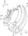
- figure 1 an optical module 10 for a motor vehicle which is intended to emit a final cut-off beam in a longitudinal direction "L".
- optical module 10 participating in a low beam function.
- Such an optical module 10 is then arranged at the front of a motor vehicle (not shown) to illuminate the road ahead of the vehicle.
- the optical module 10 mainly comprises a primary optical means 12 and a projection means 14.
- the optical module 10 also comprises at least one light sources 16, here two light sources 16.
- the light sources 16 are here formed by light-emitting diodes. There are nine of them here.
- the light emitting diodes are all carried by a common printed circuit board which extends in a horizontal plane above the primary optical means 12.
- Each light source 16 is able to transmit in a controlled manner an initial light beam which is here directed substantially vertically downwards towards an input face 18 of the primary optical means 12.
- the primary optical medium 12 is formed in one piece by a solid part made of a translucent or transparent material, such as polymethyl methacrylate (PMMA) or polycarbonate (PC).
- the primary optical means 12 comprises in its upper upper part said upper horizontal face 18 input.
- the input face 18 is provided with a plurality of collimating members 20 each of which is associated with a light source 16.
- Each member 20 is here formed by a portion of face 18 input shaped lens to collimate the light rays of the initial light beam emitted by the associated light source 16.
- the rays coming from the light source 16 propagate substantially in a vertical direction in the primary optical means 12.
- the upper input face 18 is arranged vertically to the right of a total internal reflection face 22 which is arranged to receive the initial light beam and collimated by the collimating member 20.
- This total reflection face 22 delimits the primary optical means 12 longitudinally towards the rear. It has an inclined slope shape to reflect the light rays incident globally forwards towards a front exit face 24 which delimits the optical means 12 towards the front.
- the outlet face 24 is here generated by translation of its vertical section, forming a generator, according to a concave curvature director extending in a horizontal plane.
- the light sources 16 are themselves aligned parallel to the curvature of the output face 24.
- the primary optical means 12 is provided with a cut-off member arranged to transform said reflected initial light beam into a secondary light beam oriented in a longitudinal direction and having a predetermined lower cut extending generally transversely.
- the cutoff member is formed by a notch 26 formed in a lower face of the primary optical means 12.
- the notch 26 has a reentrant upper transverse edge 28, called the cutting edge 28, whose profile corresponds to the shape of the predetermined cut. This is a flat horizontal cut.
- the cutting edge 28 is more particularly formed by the intersection between a substantially horizontal upstream first intercept face 30 and a substantially vertical downstream second face 32 which extends below the cutting edge 28.
- the intercepting face 30 is contiguous to the total reflection face 22. It is arranged to completely reflect the light rays of the secondary beam above the edge 28 in the direction of the output face 24. This intercepting face 30 thus ensures that the light rays coming from the light sources 16 are directed above the cutting edge 28. Thus, no light ray intended to form the final cut-off beam passes through the vertical downstream face 32 of the notch 28.
- the outlet face 24 arranged longitudinally downstream of the cutting edge 28.
- the face 22 of total reflection is shaped in parabola so as to focus the light rays reflected at the edge 28 of cut.
- the projection means 14 is arranged longitudinally in front and at a distance from the exit face 24 of the primary optical means 12.
- the projection means 14 is intended to project a final light beam having an upper cut-off formed by an inverted image of the sub-cut secondary light beam projected by the exit face 24 of the primary optical means 12.
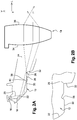
- the figure 4 illustrates the area 31 illuminated by the final beam on a transverse vertical screen 33 placed 25 meters from the lighting device, perpendicular to the optical axis whose intersection with the screen 33 corresponds to the intersection between the abscissa axis and the ordinate axis. It is observed that the area illuminated by the final beam is delimited upwards by a cutoff line 35.
- the cutoff line 28 has a horizontal rectilinear shape.
- the final beam is here a regulatory passing beam.
- the projection means 14 is formed by a lens made of a piece of transparent or translucent material such as PMMA or PC.
- the lens has an inlet rear face 34 and an opposite projection face 36.
- the input face 34 is arranged longitudinally at a distance from the exit face 24 of the primary optical means 12 for the light rays come out in the open air before entering the projection means 14.
- the projection means 14 is here formed by a separate part of the primary optical means 12.
- the projection means 14 is focused at the cutoff member. More particularly, the projection means 14 has a cylindrical shape and it comprises a transverse focal line which coincides with the cutting edge 28. This makes it possible to project a final light beam having a sharp cut formed by an inverted image of the cutting edge 28. The image is of course reversed by vertical symmetry on either side of a horizontal focal plane passing through the cutting edge 28.
- the primary optical means 12 comprises a light deflection member arranged to deflect a portion of the light rays of the initial light beam below the cut-off of the secondary beam in the direction of the projection means.
- these deviated light rays are projected upwards after passing through the projection means 14 to illuminate gantry points 37 arranged vertically above the cutoff line of the final light beam.
- the points 37 of gantry are here six in number.
- a first group of three points 37 of gantry is aligned at 2 ° above the cutoff line, a central point and two points 37 arranged at 4 ° transversely on either side of the central point.
- a second group of three gantry points 37 is aligned at 4 ° above the cut-off line, a central point and two points 37 arranged at 8 ° transversely on either side of the central point.
- the deflection member is formed by an exhaust face 38 made in the intercepting face 30.
- the exhaust face 38 more particularly forms an angle with the intercepting face 30 so as to transmit part of the initial beam outside the primary optical means 12.
- the light rays coming from the collimated initial beam thus strike the exhaust face 38 directly or after reflection on the face 22. total reflection, with an angle of incidence less than the refraction angle so that said light rays pass through the exhaust face 38 to move towards the downstream vertical face 32, below the edge 28 cut. Said deviated rays thus return again to the primary optical means 12 to move towards the exit face 24 and then towards the projection means 14.
- the exhaust face 38 is made in a bulge extending vertically projecting outwardly under the intercepting face.
- the bulge has more particularly a vertical longitudinal section in the form of a prism delimited forwardly by said exhaust face 38 and rearwardly by a rear face 40.
- the rear face 40 of the bulge is advantageously oriented so as to completely reflect the incident light rays in the direction of the exhaust face 38 to participate in the illumination of the points 37 of gantry.
- the light rays deviated by the deflection member are thus projected above the cutoff line of the final beam, to perform the regulatory function called "gantry point".
- the exhaust face 38 is made in a notch made in recess in the face 22 of interception. In vertical section, the notch is thus delimited to the rear by said exhaust face 38.
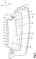
- the exhaust face 38 extends, in a horizontal plane, parallel to the output face 24 of the primary optical means 12.
- the exit face 24 having a curvature in a horizontal plane, the exhaust face 38 itself extends along a curved line.
- the exhaust face 38 extends continuously towards a plurality of light sources 16, for example six light sources 16. These are the light sources arranged to the left of the figure 3 . Thus, each of these six light sources illuminates an associated portal point.
- the exhaust face extends discontinuously under the intercepting face.
- Each exhaust face portion is then arranged in coincidence with an associated light source, each portion being separated transversely from the neighboring exhaust face portion.
- the optical module 10 described above is part of a luminous device 41 for a motor vehicle comprising said first optical module 10 produced according to the teachings of the invention, and comprising a second optical module 42 capable of producing a segmented light beam which is intended to be lit together the first optical module 10.
- the superposition of the light beams projected by the two optical modules 10, 42 makes it possible to perform a regulatory crossing-type lighting function as illustrated in FIG. figure 6 .
- the area 31 of the screen 33 illuminated by the final light beam of the first optical module 10 remains as described above. Points 37 of porticos also remain at their location.
- a second area 44 illuminated by the second optical module 42 is superimposed with the first area 31 illuminated.
- This second zone 44 has an upper portion which extends above the cutoff line of the first zone 31 illuminated on one half of the screen 33, here the right half. Said upper portion is delimited upwards by a first horizontal line 46 and laterally towards the center of the screen by a second inclined line 48, for example 15 °, which intersects with the cutoff line of the first zone 31 substantially in the center of the screen 33.
- the superposition of the two light beams illuminates a global zone 31, 44 delimited upwards by a delimitation comprising a first horizontal lower level 35, formed by the cutoff line 25 of the first zone 31, a second oblique section 48 which extends the first level 35 horizontal.
- This section 48 oblique is formed by the inclined line 48 of the second zone 44.
- a second bearing 46 upper formed by the horizontal line 46 upper second zone 44.
- the first horizontal bearing 31 makes it possible to illuminate the road while avoiding dazzling the drivers of the vehicles traveling in the opposite direction, while the second bearing 46 makes it possible to illuminate with a greater range the side of the road.
- the cut-off profile is here adapted for a vehicle traveling in a country imposing vehicles to roll on the right of the road.
- the second optical module 42 may be controlled so that the light beam is displaced to the left or to the right depending on the direction of rotation of the wheels of the vehicle, the final light beam emitted by the first optical module remaining fixed relative to to the vehicle.
- the light beam can be moved by pivoting the second optical module 42 or by selective ignition of diodes electroluminescent forming a lighting matrix of the second optical module 42.
- the optical module 10 made according to the teachings of the invention makes it possible to form a beam simultaneously illuminating gantry points.
- the deflection member of the light rays for illuminating the gantry points is arranged in the primary optical means 12.
- This primary optical means 12 is not directly visible to an observer when the optical module 10 is mounted on the vehicle. As a result, the deflection member is not visible and the optical module retains an intact and uncluttered aesthetic appearance.
- the luminous device 41 implementing the optical module 12 made according to the teachings of the invention makes it possible to illuminate the points 37 of gantry in a fixed manner while allowing the realization of a "turn code" by means of a second optical module 42.
Landscapes
- Engineering & Computer Science (AREA)
- General Engineering & Computer Science (AREA)
- Physics & Mathematics (AREA)
- Microelectronics & Electronic Packaging (AREA)
- Optics & Photonics (AREA)
- Non-Portable Lighting Devices Or Systems Thereof (AREA)
Applications Claiming Priority (1)
| Application Number | Priority Date | Filing Date | Title |
|---|---|---|---|
| FR1658120A FR3055400B1 (fr) | 2016-09-01 | 2016-09-01 | Module optique pour eclairer des points de portique |
Publications (2)
| Publication Number | Publication Date |
|---|---|
| EP3290777A1 true EP3290777A1 (de) | 2018-03-07 |
| EP3290777B1 EP3290777B1 (de) | 2023-03-01 |
Family
ID=57045212
Family Applications (1)
| Application Number | Title | Priority Date | Filing Date |
|---|---|---|---|
| EP17184962.3A Active EP3290777B1 (de) | 2016-09-01 | 2017-08-04 | Optisches modul zur beleuchtung von verkehrszeichen |
Country Status (4)
| Country | Link |
|---|---|
| US (1) | US10690309B2 (de) |
| EP (1) | EP3290777B1 (de) |
| CN (1) | CN108302457B (de) |
| FR (1) | FR3055400B1 (de) |
Cited By (9)
| Publication number | Priority date | Publication date | Assignee | Title |
|---|---|---|---|---|
| EP3653926A1 (de) * | 2018-11-19 | 2020-05-20 | ZKW Group GmbH | Beleuchtungsvorrichtung für einen kraftfahrzeugscheinwerfer sowie kraftfahrzeugscheinwerfer |
| FR3090077A1 (fr) * | 2018-12-17 | 2020-06-19 | Valeo Vision | Dispositif d’éclairage de l’habitacle d’un véhicule automobile apte à projeter un faisceau lumineux pixélisé |
| EP3671016A1 (de) * | 2018-12-21 | 2020-06-24 | ZKW Group GmbH | Beleuchtungsvorrichtung für einen kraftfahrzeugscheinwerfer sowie kraftfahrzeugscheinwerfer |
| WO2020260303A1 (fr) * | 2019-06-28 | 2020-12-30 | Valeo Vision | Pièce optique destinée à fonctionner en réflexion interne totale |
| FR3102535A1 (fr) * | 2019-10-29 | 2021-04-30 | Valeo Vision | Projecteur automobile modulable entre conduite a gauche et conduite a droite |
| WO2023164023A1 (en) * | 2022-02-28 | 2023-08-31 | J.W. Speaker Corporation | Headlamp for a vehicle |
| EP4137744A4 (de) * | 2020-07-02 | 2023-09-13 | Hasco Vision Technology Co., Ltd. | Optische einheit für fahrzeuglampe, fahrzeuglampenmodul und fahrzeug |
| EP4560185A1 (de) * | 2023-11-23 | 2025-05-28 | ZKW Group GmbH | Beleuchtungsvorrichtung für einen kraftfahrzeugscheinwerfer sowie kraftfahrzeugscheinwerfer |
| WO2025132840A1 (fr) * | 2023-12-21 | 2025-06-26 | Valeo Vision | Unite lumineuse pour vehicule automobile |
Families Citing this family (28)
| Publication number | Priority date | Publication date | Assignee | Title |
|---|---|---|---|---|
| CN108397746B (zh) * | 2018-04-13 | 2024-06-14 | 华域视觉科技(上海)有限公司 | 基于光导的远近光系统及车灯 |
| EP3581847A1 (de) * | 2018-06-13 | 2019-12-18 | Valeo Iluminacion | Kraftfahrzeugbeleuchtungsvorrichtung |
| US10760756B2 (en) * | 2018-07-06 | 2020-09-01 | H.A. Automotive Systems, Inc. | Condenser for low-beam vehicle light module |
| FR3086734B1 (fr) * | 2018-09-28 | 2022-06-24 | Valeo Vision | Module lumineux de vehicule comprenant un pion de referencement avec une partie souple et une partie rigide |
| WO2020173444A1 (zh) * | 2019-02-25 | 2020-09-03 | 华域视觉科技(上海)有限公司 | 远近光一体车灯照明装置、车灯及车辆 |
| CN110953545B (zh) * | 2019-05-21 | 2025-06-13 | 华域视觉科技(上海)有限公司 | 车灯iii区照明结构、车灯聚光器、汽车照明模组和汽车 |
| US11761603B2 (en) * | 2019-08-07 | 2023-09-19 | Lumileds Llc | Front-lighting system for vehicle |
| WO2021036215A1 (zh) * | 2019-08-23 | 2021-03-04 | 华域视觉科技(上海)有限公司 | 一种微型车灯模组 |
| CN112413530A (zh) * | 2019-08-23 | 2021-02-26 | 华域视觉科技(上海)有限公司 | 一种微型车灯模组 |
| CN112648583A (zh) * | 2019-10-12 | 2021-04-13 | 长春中锐汽车零部件有限公司 | 一种近光灯的光学结构 |
| CN210740266U (zh) * | 2019-10-25 | 2020-06-12 | 华域视觉科技(上海)有限公司 | 车灯光学元件 |
| WO2021085298A1 (ja) * | 2019-11-01 | 2021-05-06 | 市光工業株式会社 | 車両用導光体及び車両用前照灯 |
| JP7363416B2 (ja) * | 2019-11-27 | 2023-10-18 | 市光工業株式会社 | 車両用導光体及び車両用灯具ユニット |
| CN111120966B (zh) * | 2019-12-27 | 2022-05-03 | 北京车和家信息技术有限公司 | 车灯用透镜、近光灯及车辆 |
| CN212584877U (zh) | 2020-01-02 | 2021-02-23 | 法雷奥照明公司 | 导光部件、照明装置和车辆 |
| CN112781001B (zh) * | 2020-07-13 | 2025-10-03 | 华域视觉科技(上海)有限公司 | 车灯光学元件、车灯模组和车辆 |
| CN114909637A (zh) * | 2021-02-09 | 2022-08-16 | 法雷奥照明湖北技术中心有限公司 | 用于车辆的发光模块、车辆前照灯和车辆 |
| KR102949241B1 (ko) * | 2021-03-29 | 2026-04-07 | 에스엘 주식회사 | 차량용 램프 |
| JP7625982B2 (ja) * | 2021-06-11 | 2025-02-04 | 市光工業株式会社 | 車両用灯具のレンズ、車両用灯具ユニット、車両用灯具装置 |
| US20230008568A1 (en) * | 2021-07-09 | 2023-01-12 | Varroc Lighting Systems, s.r.o. | Lighting and/or signaling device for a motor vehicle and a light guide therefor |
| EP4397906A4 (de) * | 2021-08-30 | 2025-01-01 | Koito Manufacturing Co., Ltd. | Mikrolinsenanordnung und fahrzeuglampenfassung mit der mikrolinsenanordnung |
| JP7622592B2 (ja) * | 2021-09-08 | 2025-01-28 | 市光工業株式会社 | 車両用導光体及び車両用灯具ユニット |
| KR20230056465A (ko) * | 2021-10-20 | 2023-04-27 | 현대모비스 주식회사 | 차량용 램프 |
| KR20230060856A (ko) * | 2021-10-28 | 2023-05-08 | 현대모비스 주식회사 | 차량용 램프 및 그 램프를 포함하는 차량 |
| JP7845056B2 (ja) * | 2022-05-31 | 2026-04-14 | 市光工業株式会社 | 車両用導光体及び車両用灯具ユニット |
| KR20240009098A (ko) * | 2022-07-13 | 2024-01-22 | 현대모비스 주식회사 | 차량용 램프 모듈 및 그 램프 모듈을 포함하는 차량용 램프 |
| WO2026022098A1 (fr) * | 2024-07-25 | 2026-01-29 | Valeo Vision | Unite optique pour vehicule automobile et module lumineux comportant plusieurs unites optiques superposees |
| KR20260034194A (ko) * | 2024-09-04 | 2026-03-11 | 현대모비스 주식회사 | 차량용 램프 |
Citations (7)
| Publication number | Priority date | Publication date | Assignee | Title |
|---|---|---|---|---|
| DE102004047301A1 (de) * | 2003-09-29 | 2005-05-04 | Koito Mfg Co Ltd | Fahrzeugscheinwerfer |
| DE102008015510A1 (de) * | 2007-03-29 | 2008-10-02 | Koito Manufacturing Co., Ltd. | Leuchteneinheit eines Fahrzeugscheinwerfers |
| JP2010170836A (ja) * | 2009-01-22 | 2010-08-05 | Stanley Electric Co Ltd | プロジェクタ型車両用前照灯 |
| EP2730836A1 (de) * | 2012-11-09 | 2014-05-14 | Automotive Lighting Reutlingen GmbH | Lichtmodul für einen Scheinwerfer eines Kraftfahrzeugs |
| CN105066062A (zh) * | 2015-07-06 | 2015-11-18 | 隆达电子股份有限公司 | 导光柱与使用其的车用灯具 |
| DE102015215200A1 (de) * | 2014-08-11 | 2016-02-11 | Koito Manufacturing Co., Ltd. | Fahrzeugleuchte |
| EP3037716A1 (de) * | 2014-12-22 | 2016-06-29 | Stanley Electric Co., Ltd. | Fahrzeug-beleuchtungsvorrichtung mit einer laser-lichtquelle und leuchtstoffmaterial |
Family Cites Families (2)
| Publication number | Priority date | Publication date | Assignee | Title |
|---|---|---|---|---|
| EP1815287A1 (de) * | 2004-11-18 | 2007-08-08 | Koninklijke Philips Electronics N.V. | Beleuchtungssystem und fahrzeug-scheinwerfer |
| EP3333477B1 (de) * | 2014-05-23 | 2024-07-03 | Stanley Electric Co., Ltd. | Linsenkörper, beleuchtungsvorrichtung für fahrzeug |
-
2016
- 2016-09-01 FR FR1658120A patent/FR3055400B1/fr active Active
-
2017
- 2017-08-04 EP EP17184962.3A patent/EP3290777B1/de active Active
- 2017-08-31 CN CN201710777155.XA patent/CN108302457B/zh active Active
- 2017-09-01 US US15/693,629 patent/US10690309B2/en active Active
Patent Citations (7)
| Publication number | Priority date | Publication date | Assignee | Title |
|---|---|---|---|---|
| DE102004047301A1 (de) * | 2003-09-29 | 2005-05-04 | Koito Mfg Co Ltd | Fahrzeugscheinwerfer |
| DE102008015510A1 (de) * | 2007-03-29 | 2008-10-02 | Koito Manufacturing Co., Ltd. | Leuchteneinheit eines Fahrzeugscheinwerfers |
| JP2010170836A (ja) * | 2009-01-22 | 2010-08-05 | Stanley Electric Co Ltd | プロジェクタ型車両用前照灯 |
| EP2730836A1 (de) * | 2012-11-09 | 2014-05-14 | Automotive Lighting Reutlingen GmbH | Lichtmodul für einen Scheinwerfer eines Kraftfahrzeugs |
| DE102015215200A1 (de) * | 2014-08-11 | 2016-02-11 | Koito Manufacturing Co., Ltd. | Fahrzeugleuchte |
| EP3037716A1 (de) * | 2014-12-22 | 2016-06-29 | Stanley Electric Co., Ltd. | Fahrzeug-beleuchtungsvorrichtung mit einer laser-lichtquelle und leuchtstoffmaterial |
| CN105066062A (zh) * | 2015-07-06 | 2015-11-18 | 隆达电子股份有限公司 | 导光柱与使用其的车用灯具 |
Cited By (16)
| Publication number | Priority date | Publication date | Assignee | Title |
|---|---|---|---|---|
| EP3653926A1 (de) * | 2018-11-19 | 2020-05-20 | ZKW Group GmbH | Beleuchtungsvorrichtung für einen kraftfahrzeugscheinwerfer sowie kraftfahrzeugscheinwerfer |
| US11498479B2 (en) | 2018-12-17 | 2022-11-15 | Valeo Vision | Device for lighting the passenger compartment of a motor vehicle, the device being capable of projecting a pixelized light beam |
| FR3090077A1 (fr) * | 2018-12-17 | 2020-06-19 | Valeo Vision | Dispositif d’éclairage de l’habitacle d’un véhicule automobile apte à projeter un faisceau lumineux pixélisé |
| WO2020126388A1 (fr) * | 2018-12-17 | 2020-06-25 | Valeo Vision | Dispositif d'éclairage de l'habitacle d'un véhicule automobile apte à projeter un faisceau lumineux pixelisé |
| EP3671016A1 (de) * | 2018-12-21 | 2020-06-24 | ZKW Group GmbH | Beleuchtungsvorrichtung für einen kraftfahrzeugscheinwerfer sowie kraftfahrzeugscheinwerfer |
| WO2020126350A1 (de) * | 2018-12-21 | 2020-06-25 | Zkw Group Gmbh | Beleuchtungsvorrichtung für einen kraftfahrzeugscheinwerfer sowie kraftfahrzeugscheinwerfer |
| KR20210094622A (ko) * | 2018-12-21 | 2021-07-29 | 제트카베 그룹 게엠베하 | 자동차 헤드램프용 조명 장치와 자동차 헤드램프 |
| WO2020260303A1 (fr) * | 2019-06-28 | 2020-12-30 | Valeo Vision | Pièce optique destinée à fonctionner en réflexion interne totale |
| FR3097979A1 (fr) * | 2019-06-28 | 2021-01-01 | Valeo Vision | Pièce optique destinée à fonctionner en réflexion interne totale |
| US11852312B2 (en) | 2019-06-28 | 2023-12-26 | Valeo Vision | Optical component intended to operate with total internal reflection |
| WO2021083671A1 (fr) * | 2019-10-29 | 2021-05-06 | Valeo Vision | Projecteur automobile modulable entre conduite a gauche et conduite a droite |
| FR3102535A1 (fr) * | 2019-10-29 | 2021-04-30 | Valeo Vision | Projecteur automobile modulable entre conduite a gauche et conduite a droite |
| EP4137744A4 (de) * | 2020-07-02 | 2023-09-13 | Hasco Vision Technology Co., Ltd. | Optische einheit für fahrzeuglampe, fahrzeuglampenmodul und fahrzeug |
| WO2023164023A1 (en) * | 2022-02-28 | 2023-08-31 | J.W. Speaker Corporation | Headlamp for a vehicle |
| EP4560185A1 (de) * | 2023-11-23 | 2025-05-28 | ZKW Group GmbH | Beleuchtungsvorrichtung für einen kraftfahrzeugscheinwerfer sowie kraftfahrzeugscheinwerfer |
| WO2025132840A1 (fr) * | 2023-12-21 | 2025-06-26 | Valeo Vision | Unite lumineuse pour vehicule automobile |
Also Published As
| Publication number | Publication date |
|---|---|
| FR3055400A1 (fr) | 2018-03-02 |
| EP3290777B1 (de) | 2023-03-01 |
| FR3055400B1 (fr) | 2019-06-28 |
| CN108302457A (zh) | 2018-07-20 |
| US10690309B2 (en) | 2020-06-23 |
| US20180058651A1 (en) | 2018-03-01 |
| CN108302457B (zh) | 2021-05-18 |
Similar Documents
| Publication | Publication Date | Title |
|---|---|---|
| FR3055400B1 (fr) | Module optique pour eclairer des points de portique | |
| EP3604910B1 (de) | Optisches bauteil, das einen block mit einem diopter umfasst, der eine beugungseinheit für zwei lichtstrahlen bildet | |
| EP3147557B1 (de) | Primäres optisches element für kraftfahrzeugsbeleuchtungsmodul | |
| EP3002504B1 (de) | Leuchtmodul zur beleuchtung für kraftfahrzeug | |
| EP3611425B1 (de) | Leuchtmodul eines kraftfahrzeugs, das in der lage ist, einen lichtstrahl mit mindestens einer reihe von leuchteinheiten zu erzeugen | |
| EP3181991A1 (de) | Kraftfahrzeug-beleuchtungsmodul mit kombinerter abblend- und fernlichtfunktion und einer regulierbaren lichtquelle | |
| EP3844436B1 (de) | Kraftfahrzeuglichtmodul mit mehreren lichtleitern | |
| EP3315851B1 (de) | Optisches modul zum projizieren eines lichtstrahls mit hell-dunkel-grenze, das mittel zur horizontalen bündelung umfasst | |
| FR2995967B1 (fr) | Module d'eclairage, notamment pour vehicule automobile | |
| WO2019229191A1 (fr) | Module lumineux pour véhicule automobile, et dispositif d'éclairage et/ou de signalisation muni d'un tel module | |
| EP3454096B1 (de) | Fresnellinse mit variablem freiwinkel | |
| FR3103535A1 (fr) | Module lumineux imageant un dioptre formant une surface de reflexion totale | |
| EP2767752A1 (de) | Vorrichtung zur Beleuchtung und/oder Signalisierung mit torischer Linse | |
| EP3470727B1 (de) | Beleuchtungsmodul, das ein lichtmuster bildet, dessen oberer teil scharfe vertikale kanten und dessen unterer teil unscharfe vertikale kanten aufweist | |
| WO2024133349A1 (fr) | Module lumineux pour système d'éclairage d'un véhicule | |
| FR3038695A1 (fr) | Module lumineux pour l'eclairage et/ou la signalisation d'un vehicule automobile | |
| FR3055691A1 (fr) | Module d'eclairage a ecran diffractif pour vehicule automobile | |
| EP3517830B1 (de) | Strassenbeleuchtungsvorrichtung mit kontrollierter kaustik erzeugender oberfläche, die einen lichtstrahl bildet | |
| FR3084729A1 (fr) | Module lumineux bifonction signalisation et eclairage | |
| FR3139175A1 (fr) | Guide de lumière à pas élargi | |
| EP3628914B1 (de) | Optische bifunktionseinheit zum anzeigen und beleuchten | |
| WO2021018808A1 (fr) | Dispositif lumineux indicateur de changement de direction a surface generatrice de caustique controlee formant un motif sur une surface cible | |
| FR3144249A1 (fr) | Module d’éclairage | |
| WO2024061970A1 (fr) | Module lumineux | |
| WO2024251700A1 (fr) | Module d'eclairage pour vehicule automobile |
Legal Events
| Date | Code | Title | Description |
|---|---|---|---|
| PUAI | Public reference made under article 153(3) epc to a published international application that has entered the european phase |
Free format text: ORIGINAL CODE: 0009012 |
|
| STAA | Information on the status of an ep patent application or granted ep patent |
Free format text: STATUS: THE APPLICATION HAS BEEN PUBLISHED |
|
| AK | Designated contracting states |
Kind code of ref document: A1 Designated state(s): AL AT BE BG CH CY CZ DE DK EE ES FI FR GB GR HR HU IE IS IT LI LT LU LV MC MK MT NL NO PL PT RO RS SE SI SK SM TR |
|
| AX | Request for extension of the european patent |
Extension state: BA ME |
|
| STAA | Information on the status of an ep patent application or granted ep patent |
Free format text: STATUS: REQUEST FOR EXAMINATION WAS MADE |
|
| 17P | Request for examination filed |
Effective date: 20180731 |
|
| RBV | Designated contracting states (corrected) |
Designated state(s): AL AT BE BG CH CY CZ DE DK EE ES FI FR GB GR HR HU IE IS IT LI LT LU LV MC MK MT NL NO PL PT RO RS SE SI SK SM TR |
|
| STAA | Information on the status of an ep patent application or granted ep patent |
Free format text: STATUS: EXAMINATION IS IN PROGRESS |
|
| 17Q | First examination report despatched |
Effective date: 20211014 |
|
| GRAP | Despatch of communication of intention to grant a patent |
Free format text: ORIGINAL CODE: EPIDOSNIGR1 |
|
| STAA | Information on the status of an ep patent application or granted ep patent |
Free format text: STATUS: GRANT OF PATENT IS INTENDED |
|
| INTG | Intention to grant announced |
Effective date: 20220921 |
|
| GRAS | Grant fee paid |
Free format text: ORIGINAL CODE: EPIDOSNIGR3 |
|
| GRAA | (expected) grant |
Free format text: ORIGINAL CODE: 0009210 |
|
| STAA | Information on the status of an ep patent application or granted ep patent |
Free format text: STATUS: THE PATENT HAS BEEN GRANTED |
|
| AK | Designated contracting states |
Kind code of ref document: B1 Designated state(s): AL AT BE BG CH CY CZ DE DK EE ES FI FR GB GR HR HU IE IS IT LI LT LU LV MC MK MT NL NO PL PT RO RS SE SI SK SM TR |
|
| REG | Reference to a national code |
Ref country code: GB Ref legal event code: FG4D Free format text: NOT ENGLISH |
|
| REG | Reference to a national code |
Ref country code: CH Ref legal event code: EP Ref country code: AT Ref legal event code: REF Ref document number: 1551196 Country of ref document: AT Kind code of ref document: T Effective date: 20230315 |
|
| REG | Reference to a national code |
Ref country code: DE Ref legal event code: R096 Ref document number: 602017066360 Country of ref document: DE |
|
| REG | Reference to a national code |
Ref country code: IE Ref legal event code: FG4D Free format text: LANGUAGE OF EP DOCUMENT: FRENCH |
|
| REG | Reference to a national code |
Ref country code: LT Ref legal event code: MG9D |
|
| REG | Reference to a national code |
Ref country code: NL Ref legal event code: MP Effective date: 20230301 |
|
| P01 | Opt-out of the competence of the unified patent court (upc) registered |
Effective date: 20230528 |
|
| PG25 | Lapsed in a contracting state [announced via postgrant information from national office to epo] |
Ref country code: RS Free format text: LAPSE BECAUSE OF FAILURE TO SUBMIT A TRANSLATION OF THE DESCRIPTION OR TO PAY THE FEE WITHIN THE PRESCRIBED TIME-LIMIT Effective date: 20230301 Ref country code: NO Free format text: LAPSE BECAUSE OF FAILURE TO SUBMIT A TRANSLATION OF THE DESCRIPTION OR TO PAY THE FEE WITHIN THE PRESCRIBED TIME-LIMIT Effective date: 20230601 Ref country code: LV Free format text: LAPSE BECAUSE OF FAILURE TO SUBMIT A TRANSLATION OF THE DESCRIPTION OR TO PAY THE FEE WITHIN THE PRESCRIBED TIME-LIMIT Effective date: 20230301 Ref country code: LT Free format text: LAPSE BECAUSE OF FAILURE TO SUBMIT A TRANSLATION OF THE DESCRIPTION OR TO PAY THE FEE WITHIN THE PRESCRIBED TIME-LIMIT Effective date: 20230301 Ref country code: HR Free format text: LAPSE BECAUSE OF FAILURE TO SUBMIT A TRANSLATION OF THE DESCRIPTION OR TO PAY THE FEE WITHIN THE PRESCRIBED TIME-LIMIT Effective date: 20230301 Ref country code: ES Free format text: LAPSE BECAUSE OF FAILURE TO SUBMIT A TRANSLATION OF THE DESCRIPTION OR TO PAY THE FEE WITHIN THE PRESCRIBED TIME-LIMIT Effective date: 20230301 |
|
| REG | Reference to a national code |
Ref country code: AT Ref legal event code: MK05 Ref document number: 1551196 Country of ref document: AT Kind code of ref document: T Effective date: 20230301 |
|
| PG25 | Lapsed in a contracting state [announced via postgrant information from national office to epo] |
Ref country code: SE Free format text: LAPSE BECAUSE OF FAILURE TO SUBMIT A TRANSLATION OF THE DESCRIPTION OR TO PAY THE FEE WITHIN THE PRESCRIBED TIME-LIMIT Effective date: 20230301 Ref country code: PL Free format text: LAPSE BECAUSE OF FAILURE TO SUBMIT A TRANSLATION OF THE DESCRIPTION OR TO PAY THE FEE WITHIN THE PRESCRIBED TIME-LIMIT Effective date: 20230301 Ref country code: NL Free format text: LAPSE BECAUSE OF FAILURE TO SUBMIT A TRANSLATION OF THE DESCRIPTION OR TO PAY THE FEE WITHIN THE PRESCRIBED TIME-LIMIT Effective date: 20230301 Ref country code: GR Free format text: LAPSE BECAUSE OF FAILURE TO SUBMIT A TRANSLATION OF THE DESCRIPTION OR TO PAY THE FEE WITHIN THE PRESCRIBED TIME-LIMIT Effective date: 20230602 Ref country code: FI Free format text: LAPSE BECAUSE OF FAILURE TO SUBMIT A TRANSLATION OF THE DESCRIPTION OR TO PAY THE FEE WITHIN THE PRESCRIBED TIME-LIMIT Effective date: 20230301 |
|
| PG25 | Lapsed in a contracting state [announced via postgrant information from national office to epo] |
Ref country code: SM Free format text: LAPSE BECAUSE OF FAILURE TO SUBMIT A TRANSLATION OF THE DESCRIPTION OR TO PAY THE FEE WITHIN THE PRESCRIBED TIME-LIMIT Effective date: 20230301 Ref country code: RO Free format text: LAPSE BECAUSE OF FAILURE TO SUBMIT A TRANSLATION OF THE DESCRIPTION OR TO PAY THE FEE WITHIN THE PRESCRIBED TIME-LIMIT Effective date: 20230301 Ref country code: PT Free format text: LAPSE BECAUSE OF FAILURE TO SUBMIT A TRANSLATION OF THE DESCRIPTION OR TO PAY THE FEE WITHIN THE PRESCRIBED TIME-LIMIT Effective date: 20230703 Ref country code: EE Free format text: LAPSE BECAUSE OF FAILURE TO SUBMIT A TRANSLATION OF THE DESCRIPTION OR TO PAY THE FEE WITHIN THE PRESCRIBED TIME-LIMIT Effective date: 20230301 Ref country code: CZ Free format text: LAPSE BECAUSE OF FAILURE TO SUBMIT A TRANSLATION OF THE DESCRIPTION OR TO PAY THE FEE WITHIN THE PRESCRIBED TIME-LIMIT Effective date: 20230301 Ref country code: AT Free format text: LAPSE BECAUSE OF FAILURE TO SUBMIT A TRANSLATION OF THE DESCRIPTION OR TO PAY THE FEE WITHIN THE PRESCRIBED TIME-LIMIT Effective date: 20230301 |
|
| PG25 | Lapsed in a contracting state [announced via postgrant information from national office to epo] |
Ref country code: SK Free format text: LAPSE BECAUSE OF FAILURE TO SUBMIT A TRANSLATION OF THE DESCRIPTION OR TO PAY THE FEE WITHIN THE PRESCRIBED TIME-LIMIT Effective date: 20230301 Ref country code: IS Free format text: LAPSE BECAUSE OF FAILURE TO SUBMIT A TRANSLATION OF THE DESCRIPTION OR TO PAY THE FEE WITHIN THE PRESCRIBED TIME-LIMIT Effective date: 20230701 |
|
| REG | Reference to a national code |
Ref country code: DE Ref legal event code: R097 Ref document number: 602017066360 Country of ref document: DE |
|
| PLBE | No opposition filed within time limit |
Free format text: ORIGINAL CODE: 0009261 |
|
| STAA | Information on the status of an ep patent application or granted ep patent |
Free format text: STATUS: NO OPPOSITION FILED WITHIN TIME LIMIT |
|
| PG25 | Lapsed in a contracting state [announced via postgrant information from national office to epo] |
Ref country code: SI Free format text: LAPSE BECAUSE OF FAILURE TO SUBMIT A TRANSLATION OF THE DESCRIPTION OR TO PAY THE FEE WITHIN THE PRESCRIBED TIME-LIMIT Effective date: 20230301 Ref country code: DK Free format text: LAPSE BECAUSE OF FAILURE TO SUBMIT A TRANSLATION OF THE DESCRIPTION OR TO PAY THE FEE WITHIN THE PRESCRIBED TIME-LIMIT Effective date: 20230301 |
|
| 26N | No opposition filed |
Effective date: 20231204 |
|
| PG25 | Lapsed in a contracting state [announced via postgrant information from national office to epo] |
Ref country code: MC Free format text: LAPSE BECAUSE OF FAILURE TO SUBMIT A TRANSLATION OF THE DESCRIPTION OR TO PAY THE FEE WITHIN THE PRESCRIBED TIME-LIMIT Effective date: 20230301 |
|
| REG | Reference to a national code |
Ref country code: CH Ref legal event code: PL |
|
| PG25 | Lapsed in a contracting state [announced via postgrant information from national office to epo] |
Ref country code: MC Free format text: LAPSE BECAUSE OF FAILURE TO SUBMIT A TRANSLATION OF THE DESCRIPTION OR TO PAY THE FEE WITHIN THE PRESCRIBED TIME-LIMIT Effective date: 20230301 |
|
| PG25 | Lapsed in a contracting state [announced via postgrant information from national office to epo] |
Ref country code: LU Free format text: LAPSE BECAUSE OF NON-PAYMENT OF DUE FEES Effective date: 20230804 |
|
| GBPC | Gb: european patent ceased through non-payment of renewal fee |
Effective date: 20230804 |
|
| PG25 | Lapsed in a contracting state [announced via postgrant information from national office to epo] |
Ref country code: LU Free format text: LAPSE BECAUSE OF NON-PAYMENT OF DUE FEES Effective date: 20230804 Ref country code: CH Free format text: LAPSE BECAUSE OF NON-PAYMENT OF DUE FEES Effective date: 20230831 |
|
| REG | Reference to a national code |
Ref country code: BE Ref legal event code: MM Effective date: 20230831 |
|
| REG | Reference to a national code |
Ref country code: IE Ref legal event code: MM4A |
|
| PG25 | Lapsed in a contracting state [announced via postgrant information from national office to epo] |
Ref country code: IT Free format text: LAPSE BECAUSE OF FAILURE TO SUBMIT A TRANSLATION OF THE DESCRIPTION OR TO PAY THE FEE WITHIN THE PRESCRIBED TIME-LIMIT Effective date: 20230301 |
|
| PG25 | Lapsed in a contracting state [announced via postgrant information from national office to epo] |
Ref country code: IE Free format text: LAPSE BECAUSE OF NON-PAYMENT OF DUE FEES Effective date: 20230804 |
|
| PG25 | Lapsed in a contracting state [announced via postgrant information from national office to epo] |
Ref country code: GB Free format text: LAPSE BECAUSE OF NON-PAYMENT OF DUE FEES Effective date: 20230804 |
|
| PG25 | Lapsed in a contracting state [announced via postgrant information from national office to epo] |
Ref country code: IE Free format text: LAPSE BECAUSE OF NON-PAYMENT OF DUE FEES Effective date: 20230804 Ref country code: GB Free format text: LAPSE BECAUSE OF NON-PAYMENT OF DUE FEES Effective date: 20230804 |
|
| PG25 | Lapsed in a contracting state [announced via postgrant information from national office to epo] |
Ref country code: BE Free format text: LAPSE BECAUSE OF NON-PAYMENT OF DUE FEES Effective date: 20230831 |
|
| PG25 | Lapsed in a contracting state [announced via postgrant information from national office to epo] |
Ref country code: BG Free format text: LAPSE BECAUSE OF FAILURE TO SUBMIT A TRANSLATION OF THE DESCRIPTION OR TO PAY THE FEE WITHIN THE PRESCRIBED TIME-LIMIT Effective date: 20230301 |
|
| PG25 | Lapsed in a contracting state [announced via postgrant information from national office to epo] |
Ref country code: BG Free format text: LAPSE BECAUSE OF FAILURE TO SUBMIT A TRANSLATION OF THE DESCRIPTION OR TO PAY THE FEE WITHIN THE PRESCRIBED TIME-LIMIT Effective date: 20230301 |
|
| PG25 | Lapsed in a contracting state [announced via postgrant information from national office to epo] |
Ref country code: CY Free format text: LAPSE BECAUSE OF FAILURE TO SUBMIT A TRANSLATION OF THE DESCRIPTION OR TO PAY THE FEE WITHIN THE PRESCRIBED TIME-LIMIT; INVALID AB INITIO Effective date: 20170804 |
|
| PG25 | Lapsed in a contracting state [announced via postgrant information from national office to epo] |
Ref country code: HU Free format text: LAPSE BECAUSE OF FAILURE TO SUBMIT A TRANSLATION OF THE DESCRIPTION OR TO PAY THE FEE WITHIN THE PRESCRIBED TIME-LIMIT; INVALID AB INITIO Effective date: 20170804 |
|
| PGFP | Annual fee paid to national office [announced via postgrant information from national office to epo] |
Ref country code: DE Payment date: 20250812 Year of fee payment: 9 |
|
| PGFP | Annual fee paid to national office [announced via postgrant information from national office to epo] |
Ref country code: FR Payment date: 20250828 Year of fee payment: 9 |
|
| PG25 | Lapsed in a contracting state [announced via postgrant information from national office to epo] |
Ref country code: TR Free format text: LAPSE BECAUSE OF FAILURE TO SUBMIT A TRANSLATION OF THE DESCRIPTION OR TO PAY THE FEE WITHIN THE PRESCRIBED TIME-LIMIT Effective date: 20230301 |