EP3291028A1 - Transstockeur et procédé de fonctionnement d'un transstockeur - Google Patents
Transstockeur et procédé de fonctionnement d'un transstockeur Download PDFInfo
- Publication number
- EP3291028A1 EP3291028A1 EP17185414.4A EP17185414A EP3291028A1 EP 3291028 A1 EP3291028 A1 EP 3291028A1 EP 17185414 A EP17185414 A EP 17185414A EP 3291028 A1 EP3291028 A1 EP 3291028A1
- Authority
- EP
- European Patent Office
- Prior art keywords
- storage
- retrieval device
- drive
- control device
- power failure
- Prior art date
- Legal status (The legal status is an assumption and is not a legal conclusion. Google has not performed a legal analysis and makes no representation as to the accuracy of the status listed.)
- Granted
Links
Images

Classifications
-
- G—PHYSICS
- G06—COMPUTING OR CALCULATING; COUNTING
- G06F—ELECTRIC DIGITAL DATA PROCESSING
- G06F1/00—Details not covered by groups G06F3/00 - G06F13/00 and G06F21/00
- G06F1/26—Power supply means, e.g. regulation thereof
- G06F1/30—Means for acting in the event of power-supply failure or interruption, e.g. power-supply fluctuations
-
- B—PERFORMING OPERATIONS; TRANSPORTING
- B66—HOISTING; LIFTING; HAULING
- B66F—HOISTING, LIFTING, HAULING OR PUSHING, NOT OTHERWISE PROVIDED FOR, e.g. DEVICES WHICH APPLY A LIFTING OR PUSHING FORCE DIRECTLY TO THE SURFACE OF A LOAD
- B66F9/00—Devices for lifting or lowering bulky or heavy goods for loading or unloading purposes
- B66F9/06—Devices for lifting or lowering bulky or heavy goods for loading or unloading purposes movable, with their loads, on wheels or the like, e.g. fork-lift trucks
- B66F9/07—Floor-to-roof stacking devices, e.g. "stacker cranes", "retrievers"
-
- G—PHYSICS
- G05—CONTROLLING; REGULATING
- G05B—CONTROL OR REGULATING SYSTEMS IN GENERAL; FUNCTIONAL ELEMENTS OF SUCH SYSTEMS; MONITORING OR TESTING ARRANGEMENTS FOR SUCH SYSTEMS OR ELEMENTS
- G05B9/00—Safety arrangements
- G05B9/02—Safety arrangements electric
-
- G—PHYSICS
- G06—COMPUTING OR CALCULATING; COUNTING
- G06F—ELECTRIC DIGITAL DATA PROCESSING
- G06F11/00—Error detection; Error correction; Monitoring
- G06F11/07—Responding to the occurrence of a fault, e.g. fault tolerance
- G06F11/0703—Error or fault processing not based on redundancy, i.e. by taking additional measures to deal with the error or fault not making use of redundancy in operation, in hardware, or in data representation
- G06F11/0706—Error or fault processing not based on redundancy, i.e. by taking additional measures to deal with the error or fault not making use of redundancy in operation, in hardware, or in data representation the processing taking place on a specific hardware platform or in a specific software environment
- G06F11/0727—Error or fault processing not based on redundancy, i.e. by taking additional measures to deal with the error or fault not making use of redundancy in operation, in hardware, or in data representation the processing taking place on a specific hardware platform or in a specific software environment in a storage system, e.g. in a DASD or network based storage system
-
- G—PHYSICS
- G06—COMPUTING OR CALCULATING; COUNTING
- G06F—ELECTRIC DIGITAL DATA PROCESSING
- G06F11/00—Error detection; Error correction; Monitoring
- G06F11/07—Responding to the occurrence of a fault, e.g. fault tolerance
- G06F11/0703—Error or fault processing not based on redundancy, i.e. by taking additional measures to deal with the error or fault not making use of redundancy in operation, in hardware, or in data representation
- G06F11/0793—Remedial or corrective actions
-
- G—PHYSICS
- G06—COMPUTING OR CALCULATING; COUNTING
- G06F—ELECTRIC DIGITAL DATA PROCESSING
- G06F11/00—Error detection; Error correction; Monitoring
- G06F11/07—Responding to the occurrence of a fault, e.g. fault tolerance
- G06F11/0796—Safety measures, i.e. ensuring safe condition in the event of error, e.g. for controlling element
-
- G—PHYSICS
- G06—COMPUTING OR CALCULATING; COUNTING
- G06F—ELECTRIC DIGITAL DATA PROCESSING
- G06F11/00—Error detection; Error correction; Monitoring
- G06F11/30—Monitoring
- G06F11/3058—Monitoring arrangements for monitoring environmental properties or parameters of the computing system or of the computing system component, e.g. monitoring of power, currents, temperature, humidity, position, vibrations
- G06F11/3062—Monitoring arrangements for monitoring environmental properties or parameters of the computing system or of the computing system component, e.g. monitoring of power, currents, temperature, humidity, position, vibrations where the monitored property is the power consumption
Definitions
- the invention relates to a storage and retrieval device and a method for controlling a storage and retrieval device according to the preambles of the independent claims.
- Storage and retrieval equipment of the type in question are devices that serve the storage or retrieval of goods in storage facilities.
- the storage and retrieval devices are here regularly installed firmly in the camps and have both stationary installed components, such as rail systems, as well as moving components, such as manipulators for receiving the incoming and / orhyroidlagernden goods.
- Warehouse operating devices of the type in question are supplied from a fixed power grid with electrical energy.
- these storage and retrieval devices have a drive or a plurality of drives, which cause the movements of the storage and retrieval device.
- the power supply of these drives from the power grid is done here regularly via inverter.
- These converters have an electrical intermediate circuit which, during operation of the storage and retrieval device, has a direct electrical voltage, the intermediate circuit voltage.
- electromechanical brakes are used regularly, which brake the movement of the storage and retrieval device in case of failure of the power supply and fix this preferably after braking in its current position.
- Brakes are used, which are designed so that they close their energy supply when failing. In this way it is ensured that it comes to a standstill of the storage and retrieval device in case of failure of the power supply.
- the braking occurring here are relatively abrupt and thus lead to increased wear of the brakes and other mechanical components of the storage and retrieval device, such as rollers or drive wheels, or other components of the storage and retrieval device. In the worst case, this can damage the storage and retrieval device.
- the invention is therefore based on the object to show a storage and retrieval device and a method for controlling a storage and retrieval device that allow a guided shutdown of the storage and retrieval device in case of failure of an electrical energy supply network at a lower cost than is the case in the prior art.
- the object is achieved by a storage and retrieval device and a method for controlling the storage and retrieval device with the features of the independent claims.
- the features of the dependent claims relate to advantageous embodiments.
- the storage and retrieval device has a control device which comprises means for monitoring the voltage in the DC link for detecting a power failure.
- the control device monitors the voltage of the intermediate circuit of the converter and uses it to detect power failures.
- the sudden drop in voltage in the DC link as an indicator can be used, which makes it possible to react so quickly to a power failure, that it is possible to enable a guided shutdown, in particular using a regenerative operation of the drive, without having to continue to supply the drive with electrical energy.
- the emptying of the DC link takes place in case of failure of the power supply network according to the prior art usually within a few milliseconds.
- rapid detection of the power failure and a quick response to this power failure is essential, in particular to prevent the complete emptying of the DC bus and thus the loss of leadership of the drives.
- the detection of the power failure is carried out in an advantageous manner by the fact that the falling below a threshold value is used by the intermediate circuit voltage to detect a power failure.
- a threshold value is used by the intermediate circuit voltage to detect a power failure.
- An unsmoothed actual voltage in the DC link is preferably measured and compared with the threshold value. If the threshold is undershot, this is evaluated by the controller as a power failure and triggered the corresponding predetermined response of the controller to the power failure.
- the manner of the reaction to the detected power failure preferably depends on the respective operating state of the storage and retrieval device or the respective drive of the storage and retrieval device.
- the storage and retrieval device or the respective drive can be in a mode of operation in which electrical energy is converted into mechanical energy (motor mode of operation).
- a drive is used to decelerate the storage and retrieval system, it converts mechanical energy into electrical energy (regenerative mode of operation).
- the threshold value used is preferably a predetermined fraction, for example 95%, of a reference voltage, which is preferably determined continuously by the control device during operation of the storage and retrieval device.
- the determination of the reference voltage preferably also takes place from the voltage of the intermediate circuit.
- This is preferably smoothed for this, for example by the use of a Pt1 filter.
- the smoothing is preferably carried out by a delay element, in particular first order, whose time constants are ideally chosen so that the smoothed reference voltage can follow the fluctuations in the mains voltage occurring in practice and the fluctuations in the voltage of the intermediate circuit caused thereby, while the abrupt waste of the intermediate circuit voltage Power failures at least until the detection of power failure remain largely without effect on the reference voltage.
- the reference voltage is also advantageous to limit the reference voltage to an upper limit reference voltage. If the drive is in the regenerative operating phase, it is possible that the intermediate circuit voltage exceeds the intermediate circuit voltage that can be generated by the power supply network. In this context, operating states are possible in which the intermediate circuit voltage of such an excessive DC link voltage back to the predetermined by the network DC link voltage, for example, after a regenerative deceleration of movement by the drive, falls back without a power failure is present.
- the limitation of the reference voltage to a suitable marginal reference voltage can prevent the erroneous detection of power failures in such operating states.
- the reaction of the control device when detecting a power failure, in particular in a motor operating phase of the drive takes place in that the control device reverses the storage and retrieval device into a regenerative operating phase of the drive.
- This reversal into the regenerative operating phase has the advantage on the one hand that braking of the movement of the storage and retrieval device can take place via the drive due to the regenerative mode of operation of the drive.
- it has the advantage that the collapse of the intermediate circuit voltage and its emptying is prevented because the intermediate circuit can now be fed by the electrical energy generated by the drive.
- the reversal takes place in the fastest possible way, ie in particular that a speed control of the drive, which is based on the specification and adjustment of speed setpoints, is at least largely bypassed and instead a pre-control value for the drive torque is set immediately.
- This precontrol value can be stored, for example, in a data memory of the correspondingly programmed control device and, in the event of a power failure, can be called up by the control device and adjusted directly, that is to say in particular bypassing any possible control loop. In this way comparatively time-consuming control processes can be bypassed.
- the control device preferably performs a deceleration of the movement of the storage and retrieval device by the drive.
- braking acting - drive torque increases time-dependent, for example, is increased in a ramp.
- This can also be stored by a predetermined course Control values that are passed from the control device to the drive, be realized.
- control of this deceleration phase may also be possible for the control of this deceleration phase to resort to an optionally previously, in particular during Um Kunststoffvorgangs bypassed control, in particular speed control.
- the storage and retrieval device may be advantageous to use the energy regeneratively generated by the drive, which is output to the intermediate circuit, in order to supply the power supply of the control device and / or preferably the electromechanical brake of the storage and retrieval device with voltage.
- the storage and retrieval device preferably has a power supply device fed from the intermediate circuit. This can be, for example, a wide-range power supply, which control device and / or braking of the storage and retrieval device can supply so until the end of the guided shutdown of the storage and retrieval device with the required energy.
- the control device is preferably designed such that it activates the brake of the storage and retrieval device after detecting a power failure, ie in particular closes as soon as a predeterminable limit speed of the storage and retrieval device is exceeded.
- a particularly gentle braking of the storage and retrieval device it is of particular advantage if the brake is incident upon reaching the standstill of the braked in regenerative operation of the drive. Practically, however, the dropping below a certain limit speed is already sufficient, below which an abrupt braking of the residual movement by the incident brake can be regarded as uncritical with regard to the mechanical loads of the storage and retrieval device.
- the brake is advantageously activated directly by the controller to immediately shut down the storage operator in just this position. A slight “sagging" of the possibly held by the drive storage and retrieval device to the final stop by the brake can be taken into account here.
- the advantageously optionally provided energy storage devices need only necessary for the control of the drives auxiliary systems, ie the control device itself, the electro-mechanical brake and possibly existing programmable logic controllers, security and fieldbus systems, etc. until the final standstill of Be able to provide energy to the storage and retrieval unit.
- the electrical power is required for this purpose, which would be necessary according to the prior art described above, to provide the drives themselves with the required electrical energy.
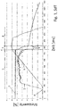
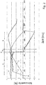
- the measured values are given as dimensionless relative values of a respective reference value.
- the absolute measurements are not essential to the understanding of the present invention. Therefore, relative measured values were formed for the individual measured parameters with corresponding reference values in order to be able to display the individual data graphs in a meaningful way with a common scaling.
- the Fig. 1 to 3 each show the curves of the drive speed 1, the drive torque 2 and the intermediate circuit voltage 3 of a storage and retrieval device.
- Fig. 1 it is an exemplary storage and retrieval device according to the prior art, which is stopped or braked in a conventional manner.
- the voltage in the DC link shows the value typical for trouble-free mains operation.
- the drive passes through an acceleration phase 5, in which the drive speed 1 increases while still remaining DC link voltage 3.
- the drive torque 2 initially also increases, in order to achieve a largely constant value in the context of technical fluctuations after a short time.
- the braking phase 8 connects. In this no measurable drive torque 2 more.
- the intermediate circuit voltage 3 gradually decreases, starting from a residual voltage value which is no longer sufficient for the supply of the drive.
- the drive speed 1 initially remains due to the inertia initially still relatively constant until the brake of the storage and retrieval device, which has been activated due to the detected by conventional methods power failure, closes and causes by the onset of braking a relatively steep drop in the drive speed 1 to zero. In the example shown, it takes about 150 ms from the onset of braking until the drive stops.
- Fig. 2 are the corresponding parameter curves for a power failure experiment with a storage and retrieval device according to the invention shown.
- the inventive method for controlling the storage and retrieval device used is the inventive method for controlling the storage and retrieval device used.
- reaction phase 9 causes the control device when detecting the power failure advantageously reversing the drive.
- this is advantageously effected by first setting the drive torque 2 to a pilot control value of zero and reversing the drive from a motor to a generator operating phase.
- the regenerative drive torque 2 - in Fig. 2 recognizable by the negative sign - is then increased in the example shown in the form of a ramp.
- the intermediate circuit voltage 3 drops only minimally before it is stabilized again by the energy fed back by the drive. As a result, starting from the moment of reversing, a phase of the steady decline of the drive speed 1 begins. The intermediate circuit voltage 3 is maintained in this phase by the electrical energy fed back by the generator-operated drive. In the example shown here even an intermediate circuit voltage 3 is reached above the level of the intermediate circuit voltage 3 in network operation.
- the drive speed 1 of the drive thus begins to decrease immediately after the time of the power failure.
- the drive speed 1 and thus the speed of movement of the storage and retrieval device reduces over a period of about 500 ms to zero. In this way, a significantly smoother shutdown of the storage and retrieval device is achieved than after in Fig. 1 illustrated prior art.
- Fig. 2 described method in an advantageous variant application, in which the reversing takes place in an advantageous manner by setting a predetermined pilot value for the drive torque, which already corresponds to a defined braking torque in the regenerative operation of the drive.
- Fig. 3 This can be seen from the fact that the drive torque 2 is set immediately after the time of power failure 6 for a very short period of time to an excessive pre-control value of -30%, which already corresponds to a significant braking torque.
- the now regenerative or braking drive torque 2 is then set in the example shown to the starting value of a ramp.
- This starting value corresponds to a lower braking torque than the excessive pilot control value.
- the braking torque - similar to Fig. 2 described - again increased to a standstill of the drive or the storage and retrieval device.
- the storage and retrieval device comes to a standstill in a period of about 400 ms, ie the duration of the deceleration process is shortened by the temporarily excessive pilot value (and the resulting torque boost) due to the faster Umkommutierens.
- the storage and retrieval device comes to a standstill in a period of about 400 ms, ie the duration of the deceleration process is shortened by the temporarily excessive pilot value (and the resulting torque boost) due to the faster Umkommutierens.
- the storage and retrieval device comes to a standstill in a period of about 400 ms, ie the duration of the deceleration process is shortened by the temporarily excessive pilot value (and the resulting torque boost) due to the faster Umkommutierens.
- more electrical energy is fed back from the drive into the DC link than in the case of Fig. 2 illustrated method variant.
Landscapes
- Engineering & Computer Science (AREA)
- Theoretical Computer Science (AREA)
- General Physics & Mathematics (AREA)
- Physics & Mathematics (AREA)
- General Engineering & Computer Science (AREA)
- Quality & Reliability (AREA)
- Structural Engineering (AREA)
- Transportation (AREA)
- Computing Systems (AREA)
- Civil Engineering (AREA)
- Life Sciences & Earth Sciences (AREA)
- Geology (AREA)
- Mechanical Engineering (AREA)
- Automation & Control Theory (AREA)
- Stopping Of Electric Motors (AREA)
- Charge And Discharge Circuits For Batteries Or The Like (AREA)
Applications Claiming Priority (1)
| Application Number | Priority Date | Filing Date | Title |
|---|---|---|---|
| DE102016010327.2A DE102016010327A1 (de) | 2016-08-29 | 2016-08-29 | Lagerbediengerät und Verfahren zur Steuerung eines Lagerbediengeräts |
Publications (2)
| Publication Number | Publication Date |
|---|---|
| EP3291028A1 true EP3291028A1 (fr) | 2018-03-07 |
| EP3291028B1 EP3291028B1 (fr) | 2024-03-13 |
Family
ID=59745153
Family Applications (1)
| Application Number | Title | Priority Date | Filing Date |
|---|---|---|---|
| EP17185414.4A Active EP3291028B1 (fr) | 2016-08-29 | 2017-08-08 | Transstockeur et procédé de fonctionnement d'un transstockeur |
Country Status (3)
| Country | Link |
|---|---|
| US (1) | US10775864B2 (fr) |
| EP (1) | EP3291028B1 (fr) |
| DE (1) | DE102016010327A1 (fr) |
Families Citing this family (1)
| Publication number | Priority date | Publication date | Assignee | Title |
|---|---|---|---|---|
| EP3629469A1 (fr) | 2018-09-28 | 2020-04-01 | Siemens Aktiengesellschaft | Dispositif de transport à courroie ainsi que procédé de maintien d'une courroie d'un dispositif de transport à courroie |
Citations (3)
| Publication number | Priority date | Publication date | Assignee | Title |
|---|---|---|---|---|
| US5917297A (en) * | 1996-07-25 | 1999-06-29 | Lust Antriebstechnik Gmbh | Arrangement and method for operating a magnetically suspended, electromotoric drive apparatus in the event of a mains disturbance |
| US20130151199A1 (en) * | 2011-12-07 | 2013-06-13 | Steven Ross Hadley | Systems and methods for use in monitoring an industrial facility |
| DE102014220165A1 (de) | 2014-10-06 | 2016-04-07 | Viastore Systems Gmbh | Regalbediengerät und Verfahren zum Steuern eines Regalbediengeräts |
Family Cites Families (9)
| Publication number | Priority date | Publication date | Assignee | Title |
|---|---|---|---|---|
| JP2002362710A (ja) | 2001-06-04 | 2002-12-18 | Murata Mach Ltd | 走行台車 |
| US20060129374A1 (en) * | 2004-12-15 | 2006-06-15 | Larson Lee A | Apparatus and method for apparatus mediating voltage levels between an emulation unit and a target processor |
| DE102006015031A1 (de) * | 2006-03-31 | 2007-10-11 | Siemens Ag | Verfahren zur Verringerung des Blindleistungsbedarfs eines grundfrequent getakteten netzseitigen Stromrichters im Leerlauf sowie bei geringer motorischer Belastung |
| JP5527995B2 (ja) | 2009-03-31 | 2014-06-25 | 株式会社Ihiインフラシステム | 負荷駆動装置 |
| DE102009017023A1 (de) * | 2009-04-14 | 2010-10-28 | Siemens Aktiengesellschaft | Antriebssystem für eine Anlage mit einem Wechselspannungsinselnetz |
| DE102013226763A1 (de) * | 2013-12-19 | 2015-06-25 | Bayerische Motoren Werke Aktiengesellschaft | Sicherheitsschaltungsanordnung für eine elektrische Antriebseinheit |
| WO2015104825A1 (fr) * | 2014-01-10 | 2015-07-16 | 株式会社日立産機システム | Dispositif de conversion d'alimentation électrique |
| JP6377985B2 (ja) * | 2014-07-24 | 2018-08-22 | ファナック株式会社 | 停電時におけるトルク指令制限機能を備えたモータ制御装置 |
| JP6356716B2 (ja) * | 2016-02-29 | 2018-07-11 | ファナック株式会社 | トルク指令制限部を有するモータ制御装置 |
-
2016
- 2016-08-29 DE DE102016010327.2A patent/DE102016010327A1/de active Pending
-
2017
- 2017-08-08 EP EP17185414.4A patent/EP3291028B1/fr active Active
- 2017-08-11 US US15/674,760 patent/US10775864B2/en active Active
Patent Citations (3)
| Publication number | Priority date | Publication date | Assignee | Title |
|---|---|---|---|---|
| US5917297A (en) * | 1996-07-25 | 1999-06-29 | Lust Antriebstechnik Gmbh | Arrangement and method for operating a magnetically suspended, electromotoric drive apparatus in the event of a mains disturbance |
| US20130151199A1 (en) * | 2011-12-07 | 2013-06-13 | Steven Ross Hadley | Systems and methods for use in monitoring an industrial facility |
| DE102014220165A1 (de) | 2014-10-06 | 2016-04-07 | Viastore Systems Gmbh | Regalbediengerät und Verfahren zum Steuern eines Regalbediengeräts |
Also Published As
| Publication number | Publication date |
|---|---|
| US10775864B2 (en) | 2020-09-15 |
| DE102016010327A1 (de) | 2018-03-01 |
| EP3291028B1 (fr) | 2024-03-13 |
| US20180059760A1 (en) | 2018-03-01 |
Similar Documents
| Publication | Publication Date | Title |
|---|---|---|
| DE102015108889B4 (de) | Motorsteuervorrichtung mit Schutzeinheit eines Ladewiderstands | |
| DE102016110370B4 (de) | Servomotor-stoppsteuerung zum steuern und stoppen eines servomotors während eines notstopps | |
| EP2542456B1 (fr) | Procédé de réalisation d'un freinage d'urgence | |
| DE102017008916A1 (de) | Produktionssystem zum Ausführen von kooperativer Arbeit durch eine Bedienperson und einen Roboter | |
| EP3017917B1 (fr) | Procede et systeme d'immobilisation d'axes d'un robot industriel | |
| DE102010044644A1 (de) | Verfahren zur Kollisionserkennung für eine Antriebseinheit | |
| EP2887535A1 (fr) | Système d'entraînement et de commande pour portes relevables | |
| DE102014116257A1 (de) | Motorsteuerung für einen Schutz des Werkzeugs und des zu bearbeitenden Objekts bei einem Schnellstopp | |
| DE102015210431A1 (de) | Verfahren zum Ansteuern einer Feststellbremse in einem Fahrzeug | |
| DE102010023536A1 (de) | Vorrichtung und Verfahren zur intelligenten antriebsbasierten Netzleistungsregulierung durch kinetische Energiespeicherung | |
| EP1602014B1 (fr) | Procede et dispositif de commande d'un entrainement de porte | |
| EP1920300A2 (fr) | Procede et dispositif pour la surveillance automatique d'operations repetitives d'une presse d'injection | |
| DE102009035449B3 (de) | Verfahren und Vorrichtung zur zeitgesteuerten Einklemmerkennung | |
| EP3291028B1 (fr) | Transstockeur et procédé de fonctionnement d'un transstockeur | |
| WO2014067894A1 (fr) | Dispositif permettant d'éviter une vitesse excessive d'un battant de porte due à un accumulateur d'énergie | |
| EP2175552A1 (fr) | Procédé de fonctionnement d'un dispositif d'entraînement et dispositif d'entraînement destiné à l'exécution du procédé | |
| DE102016114038B4 (de) | Servomotor-Steuervorrichtung | |
| EP3543200B1 (fr) | Procédé de commande d'un transtockeur | |
| DE10254608B4 (de) | Antriebssystem | |
| WO2008092581A1 (fr) | Dispositif et procédé pour un test de fonctionnement d'un frein | |
| DE102011083574A1 (de) | Verfahren und Vorrichtung zum Bewegen einer Warenbahn | |
| DE102017204123A1 (de) | Verfahren zum Bremsen einer Maschine und Maschine | |
| DE102015008436A1 (de) | Energieversorgungseinrichtung | |
| EP2736832A1 (fr) | Procédé de commande du mouvement longitudinal d'un véhicule ferroviaire, dispositif de commande en virage, et véhicule ferroviaire | |
| WO2014033205A1 (fr) | Procédé de commande de la manœuvre de fermeture de dispositifs de fermeture comprenant un élément mobile entraîné par un moteur électrique |
Legal Events
| Date | Code | Title | Description |
|---|---|---|---|
| PUAI | Public reference made under article 153(3) epc to a published international application that has entered the european phase |
Free format text: ORIGINAL CODE: 0009012 |
|
| STAA | Information on the status of an ep patent application or granted ep patent |
Free format text: STATUS: THE APPLICATION HAS BEEN PUBLISHED |
|
| AK | Designated contracting states |
Kind code of ref document: A1 Designated state(s): AL AT BE BG CH CY CZ DE DK EE ES FI FR GB GR HR HU IE IS IT LI LT LU LV MC MK MT NL NO PL PT RO RS SE SI SK SM TR |
|
| AX | Request for extension of the european patent |
Extension state: BA ME |
|
| STAA | Information on the status of an ep patent application or granted ep patent |
Free format text: STATUS: REQUEST FOR EXAMINATION WAS MADE |
|
| 17P | Request for examination filed |
Effective date: 20180904 |
|
| RBV | Designated contracting states (corrected) |
Designated state(s): AL AT BE BG CH CY CZ DE DK EE ES FI FR GB GR HR HU IE IS IT LI LT LU LV MC MK MT NL NO PL PT RO RS SE SI SK SM TR |
|
| STAA | Information on the status of an ep patent application or granted ep patent |
Free format text: STATUS: EXAMINATION IS IN PROGRESS |
|
| 17Q | First examination report despatched |
Effective date: 20210528 |
|
| GRAP | Despatch of communication of intention to grant a patent |
Free format text: ORIGINAL CODE: EPIDOSNIGR1 |
|
| STAA | Information on the status of an ep patent application or granted ep patent |
Free format text: STATUS: GRANT OF PATENT IS INTENDED |
|
| INTG | Intention to grant announced |
Effective date: 20230925 |
|
| GRAS | Grant fee paid |
Free format text: ORIGINAL CODE: EPIDOSNIGR3 |
|
| GRAA | (expected) grant |
Free format text: ORIGINAL CODE: 0009210 |
|
| STAA | Information on the status of an ep patent application or granted ep patent |
Free format text: STATUS: THE PATENT HAS BEEN GRANTED |
|
| AK | Designated contracting states |
Kind code of ref document: B1 Designated state(s): AL AT BE BG CH CY CZ DE DK EE ES FI FR GB GR HR HU IE IS IT LI LT LU LV MC MK MT NL NO PL PT RO RS SE SI SK SM TR |
|
| REG | Reference to a national code |
Ref country code: GB Ref legal event code: FG4D Free format text: NOT ENGLISH |
|
| REG | Reference to a national code |
Ref country code: CH Ref legal event code: EP |
|
| REG | Reference to a national code |
Ref country code: DE Ref legal event code: R096 Ref document number: 502017015919 Country of ref document: DE |
|
| REG | Reference to a national code |
Ref country code: IE Ref legal event code: FG4D Free format text: LANGUAGE OF EP DOCUMENT: GERMAN |
|
| PG25 | Lapsed in a contracting state [announced via postgrant information from national office to epo] |
Ref country code: LT Free format text: LAPSE BECAUSE OF FAILURE TO SUBMIT A TRANSLATION OF THE DESCRIPTION OR TO PAY THE FEE WITHIN THE PRESCRIBED TIME-LIMIT Effective date: 20240313 |
|
| REG | Reference to a national code |
Ref country code: LT Ref legal event code: MG9D |
|
| PG25 | Lapsed in a contracting state [announced via postgrant information from national office to epo] |
Ref country code: GR Free format text: LAPSE BECAUSE OF FAILURE TO SUBMIT A TRANSLATION OF THE DESCRIPTION OR TO PAY THE FEE WITHIN THE PRESCRIBED TIME-LIMIT Effective date: 20240614 |
|
| REG | Reference to a national code |
Ref country code: NL Ref legal event code: MP Effective date: 20240313 |
|
| PG25 | Lapsed in a contracting state [announced via postgrant information from national office to epo] |
Ref country code: RS Free format text: LAPSE BECAUSE OF FAILURE TO SUBMIT A TRANSLATION OF THE DESCRIPTION OR TO PAY THE FEE WITHIN THE PRESCRIBED TIME-LIMIT Effective date: 20240613 Ref country code: HR Free format text: LAPSE BECAUSE OF FAILURE TO SUBMIT A TRANSLATION OF THE DESCRIPTION OR TO PAY THE FEE WITHIN THE PRESCRIBED TIME-LIMIT Effective date: 20240313 |
|
| PG25 | Lapsed in a contracting state [announced via postgrant information from national office to epo] |
Ref country code: ES Free format text: LAPSE BECAUSE OF FAILURE TO SUBMIT A TRANSLATION OF THE DESCRIPTION OR TO PAY THE FEE WITHIN THE PRESCRIBED TIME-LIMIT Effective date: 20240313 |
|
| PG25 | Lapsed in a contracting state [announced via postgrant information from national office to epo] |
Ref country code: RS Free format text: LAPSE BECAUSE OF FAILURE TO SUBMIT A TRANSLATION OF THE DESCRIPTION OR TO PAY THE FEE WITHIN THE PRESCRIBED TIME-LIMIT Effective date: 20240613 Ref country code: NO Free format text: LAPSE BECAUSE OF FAILURE TO SUBMIT A TRANSLATION OF THE DESCRIPTION OR TO PAY THE FEE WITHIN THE PRESCRIBED TIME-LIMIT Effective date: 20240613 Ref country code: LT Free format text: LAPSE BECAUSE OF FAILURE TO SUBMIT A TRANSLATION OF THE DESCRIPTION OR TO PAY THE FEE WITHIN THE PRESCRIBED TIME-LIMIT Effective date: 20240313 Ref country code: HR Free format text: LAPSE BECAUSE OF FAILURE TO SUBMIT A TRANSLATION OF THE DESCRIPTION OR TO PAY THE FEE WITHIN THE PRESCRIBED TIME-LIMIT Effective date: 20240313 Ref country code: GR Free format text: LAPSE BECAUSE OF FAILURE TO SUBMIT A TRANSLATION OF THE DESCRIPTION OR TO PAY THE FEE WITHIN THE PRESCRIBED TIME-LIMIT Effective date: 20240614 Ref country code: FI Free format text: LAPSE BECAUSE OF FAILURE TO SUBMIT A TRANSLATION OF THE DESCRIPTION OR TO PAY THE FEE WITHIN THE PRESCRIBED TIME-LIMIT Effective date: 20240313 Ref country code: ES Free format text: LAPSE BECAUSE OF FAILURE TO SUBMIT A TRANSLATION OF THE DESCRIPTION OR TO PAY THE FEE WITHIN THE PRESCRIBED TIME-LIMIT Effective date: 20240313 Ref country code: BG Free format text: LAPSE BECAUSE OF FAILURE TO SUBMIT A TRANSLATION OF THE DESCRIPTION OR TO PAY THE FEE WITHIN THE PRESCRIBED TIME-LIMIT Effective date: 20240313 |
|
| PG25 | Lapsed in a contracting state [announced via postgrant information from national office to epo] |
Ref country code: SE Free format text: LAPSE BECAUSE OF FAILURE TO SUBMIT A TRANSLATION OF THE DESCRIPTION OR TO PAY THE FEE WITHIN THE PRESCRIBED TIME-LIMIT Effective date: 20240313 Ref country code: LV Free format text: LAPSE BECAUSE OF FAILURE TO SUBMIT A TRANSLATION OF THE DESCRIPTION OR TO PAY THE FEE WITHIN THE PRESCRIBED TIME-LIMIT Effective date: 20240313 |
|
| PG25 | Lapsed in a contracting state [announced via postgrant information from national office to epo] |
Ref country code: NL Free format text: LAPSE BECAUSE OF FAILURE TO SUBMIT A TRANSLATION OF THE DESCRIPTION OR TO PAY THE FEE WITHIN THE PRESCRIBED TIME-LIMIT Effective date: 20240313 |
|
| PG25 | Lapsed in a contracting state [announced via postgrant information from national office to epo] |
Ref country code: NL Free format text: LAPSE BECAUSE OF FAILURE TO SUBMIT A TRANSLATION OF THE DESCRIPTION OR TO PAY THE FEE WITHIN THE PRESCRIBED TIME-LIMIT Effective date: 20240313 |
|
| PG25 | Lapsed in a contracting state [announced via postgrant information from national office to epo] |
Ref country code: IS Free format text: LAPSE BECAUSE OF FAILURE TO SUBMIT A TRANSLATION OF THE DESCRIPTION OR TO PAY THE FEE WITHIN THE PRESCRIBED TIME-LIMIT Effective date: 20240713 |
|
| PG25 | Lapsed in a contracting state [announced via postgrant information from national office to epo] |
Ref country code: PT Free format text: LAPSE BECAUSE OF FAILURE TO SUBMIT A TRANSLATION OF THE DESCRIPTION OR TO PAY THE FEE WITHIN THE PRESCRIBED TIME-LIMIT Effective date: 20240715 Ref country code: SM Free format text: LAPSE BECAUSE OF FAILURE TO SUBMIT A TRANSLATION OF THE DESCRIPTION OR TO PAY THE FEE WITHIN THE PRESCRIBED TIME-LIMIT Effective date: 20240313 |
|
| PG25 | Lapsed in a contracting state [announced via postgrant information from national office to epo] |
Ref country code: EE Free format text: LAPSE BECAUSE OF FAILURE TO SUBMIT A TRANSLATION OF THE DESCRIPTION OR TO PAY THE FEE WITHIN THE PRESCRIBED TIME-LIMIT Effective date: 20240313 Ref country code: CZ Free format text: LAPSE BECAUSE OF FAILURE TO SUBMIT A TRANSLATION OF THE DESCRIPTION OR TO PAY THE FEE WITHIN THE PRESCRIBED TIME-LIMIT Effective date: 20240313 |
|
| PG25 | Lapsed in a contracting state [announced via postgrant information from national office to epo] |
Ref country code: PL Free format text: LAPSE BECAUSE OF FAILURE TO SUBMIT A TRANSLATION OF THE DESCRIPTION OR TO PAY THE FEE WITHIN THE PRESCRIBED TIME-LIMIT Effective date: 20240313 |
|
| PG25 | Lapsed in a contracting state [announced via postgrant information from national office to epo] |
Ref country code: SK Free format text: LAPSE BECAUSE OF FAILURE TO SUBMIT A TRANSLATION OF THE DESCRIPTION OR TO PAY THE FEE WITHIN THE PRESCRIBED TIME-LIMIT Effective date: 20240313 |
|
| PG25 | Lapsed in a contracting state [announced via postgrant information from national office to epo] |
Ref country code: SM Free format text: LAPSE BECAUSE OF FAILURE TO SUBMIT A TRANSLATION OF THE DESCRIPTION OR TO PAY THE FEE WITHIN THE PRESCRIBED TIME-LIMIT Effective date: 20240313 Ref country code: SK Free format text: LAPSE BECAUSE OF FAILURE TO SUBMIT A TRANSLATION OF THE DESCRIPTION OR TO PAY THE FEE WITHIN THE PRESCRIBED TIME-LIMIT Effective date: 20240313 Ref country code: RO Free format text: LAPSE BECAUSE OF FAILURE TO SUBMIT A TRANSLATION OF THE DESCRIPTION OR TO PAY THE FEE WITHIN THE PRESCRIBED TIME-LIMIT Effective date: 20240313 Ref country code: PT Free format text: LAPSE BECAUSE OF FAILURE TO SUBMIT A TRANSLATION OF THE DESCRIPTION OR TO PAY THE FEE WITHIN THE PRESCRIBED TIME-LIMIT Effective date: 20240715 Ref country code: PL Free format text: LAPSE BECAUSE OF FAILURE TO SUBMIT A TRANSLATION OF THE DESCRIPTION OR TO PAY THE FEE WITHIN THE PRESCRIBED TIME-LIMIT Effective date: 20240313 Ref country code: IS Free format text: LAPSE BECAUSE OF FAILURE TO SUBMIT A TRANSLATION OF THE DESCRIPTION OR TO PAY THE FEE WITHIN THE PRESCRIBED TIME-LIMIT Effective date: 20240713 Ref country code: EE Free format text: LAPSE BECAUSE OF FAILURE TO SUBMIT A TRANSLATION OF THE DESCRIPTION OR TO PAY THE FEE WITHIN THE PRESCRIBED TIME-LIMIT Effective date: 20240313 Ref country code: CZ Free format text: LAPSE BECAUSE OF FAILURE TO SUBMIT A TRANSLATION OF THE DESCRIPTION OR TO PAY THE FEE WITHIN THE PRESCRIBED TIME-LIMIT Effective date: 20240313 |
|
| PG25 | Lapsed in a contracting state [announced via postgrant information from national office to epo] |
Ref country code: IT Free format text: LAPSE BECAUSE OF FAILURE TO SUBMIT A TRANSLATION OF THE DESCRIPTION OR TO PAY THE FEE WITHIN THE PRESCRIBED TIME-LIMIT Effective date: 20240313 |
|
| REG | Reference to a national code |
Ref country code: DE Ref legal event code: R097 Ref document number: 502017015919 Country of ref document: DE |
|
| PG25 | Lapsed in a contracting state [announced via postgrant information from national office to epo] |
Ref country code: IT Free format text: LAPSE BECAUSE OF FAILURE TO SUBMIT A TRANSLATION OF THE DESCRIPTION OR TO PAY THE FEE WITHIN THE PRESCRIBED TIME-LIMIT Effective date: 20240313 |
|
| PG25 | Lapsed in a contracting state [announced via postgrant information from national office to epo] |
Ref country code: DK Free format text: LAPSE BECAUSE OF FAILURE TO SUBMIT A TRANSLATION OF THE DESCRIPTION OR TO PAY THE FEE WITHIN THE PRESCRIBED TIME-LIMIT Effective date: 20240313 |
|
| PLBE | No opposition filed within time limit |
Free format text: ORIGINAL CODE: 0009261 |
|
| STAA | Information on the status of an ep patent application or granted ep patent |
Free format text: STATUS: NO OPPOSITION FILED WITHIN TIME LIMIT |
|
| PG25 | Lapsed in a contracting state [announced via postgrant information from national office to epo] |
Ref country code: DK Free format text: LAPSE BECAUSE OF FAILURE TO SUBMIT A TRANSLATION OF THE DESCRIPTION OR TO PAY THE FEE WITHIN THE PRESCRIBED TIME-LIMIT Effective date: 20240313 |
|
| 26N | No opposition filed |
Effective date: 20241216 |
|
| REG | Reference to a national code |
Ref country code: CH Ref legal event code: PL |
|
| PG25 | Lapsed in a contracting state [announced via postgrant information from national office to epo] |
Ref country code: LU Free format text: LAPSE BECAUSE OF NON-PAYMENT OF DUE FEES Effective date: 20240808 |
|
| GBPC | Gb: european patent ceased through non-payment of renewal fee |
Effective date: 20240808 |
|
| PG25 | Lapsed in a contracting state [announced via postgrant information from national office to epo] |
Ref country code: SI Free format text: LAPSE BECAUSE OF FAILURE TO SUBMIT A TRANSLATION OF THE DESCRIPTION OR TO PAY THE FEE WITHIN THE PRESCRIBED TIME-LIMIT Effective date: 20240313 Ref country code: MC Free format text: LAPSE BECAUSE OF FAILURE TO SUBMIT A TRANSLATION OF THE DESCRIPTION OR TO PAY THE FEE WITHIN THE PRESCRIBED TIME-LIMIT Effective date: 20240313 Ref country code: CH Free format text: LAPSE BECAUSE OF NON-PAYMENT OF DUE FEES Effective date: 20240831 |
|
| REG | Reference to a national code |
Ref country code: BE Ref legal event code: MM Effective date: 20240831 |
|
| PG25 | Lapsed in a contracting state [announced via postgrant information from national office to epo] |
Ref country code: GB Free format text: LAPSE BECAUSE OF NON-PAYMENT OF DUE FEES Effective date: 20240808 |
|
| PG25 | Lapsed in a contracting state [announced via postgrant information from national office to epo] |
Ref country code: BE Free format text: LAPSE BECAUSE OF NON-PAYMENT OF DUE FEES Effective date: 20240831 |
|
| PG25 | Lapsed in a contracting state [announced via postgrant information from national office to epo] |
Ref country code: FR Free format text: LAPSE BECAUSE OF NON-PAYMENT OF DUE FEES Effective date: 20240831 |
|
| PG25 | Lapsed in a contracting state [announced via postgrant information from national office to epo] |
Ref country code: IE Free format text: LAPSE BECAUSE OF NON-PAYMENT OF DUE FEES Effective date: 20240808 |
|
| PGFP | Annual fee paid to national office [announced via postgrant information from national office to epo] |
Ref country code: DE Payment date: 20250819 Year of fee payment: 9 |
|
| REG | Reference to a national code |
Ref country code: AT Ref legal event code: MM01 Ref document number: 1666332 Country of ref document: AT Kind code of ref document: T Effective date: 20240808 |
|
| PG25 | Lapsed in a contracting state [announced via postgrant information from national office to epo] |
Ref country code: AT Free format text: LAPSE BECAUSE OF NON-PAYMENT OF DUE FEES Effective date: 20240808 |
|
| PG25 | Lapsed in a contracting state [announced via postgrant information from national office to epo] |
Ref country code: CY Free format text: LAPSE BECAUSE OF FAILURE TO SUBMIT A TRANSLATION OF THE DESCRIPTION OR TO PAY THE FEE WITHIN THE PRESCRIBED TIME-LIMIT; INVALID AB INITIO Effective date: 20170808 |
|
| PG25 | Lapsed in a contracting state [announced via postgrant information from national office to epo] |
Ref country code: HU Free format text: LAPSE BECAUSE OF FAILURE TO SUBMIT A TRANSLATION OF THE DESCRIPTION OR TO PAY THE FEE WITHIN THE PRESCRIBED TIME-LIMIT; INVALID AB INITIO Effective date: 20170808 |