EP1602014B1 - Procede et dispositif de commande d'un entrainement de porte - Google Patents
Procede et dispositif de commande d'un entrainement de porte Download PDFInfo
- Publication number
- EP1602014B1 EP1602014B1 EP04713046A EP04713046A EP1602014B1 EP 1602014 B1 EP1602014 B1 EP 1602014B1 EP 04713046 A EP04713046 A EP 04713046A EP 04713046 A EP04713046 A EP 04713046A EP 1602014 B1 EP1602014 B1 EP 1602014B1
- Authority
- EP
- European Patent Office
- Prior art keywords
- door drive
- speed
- torques
- torque
- maximum
- Prior art date
- Legal status (The legal status is an assumption and is not a legal conclusion. Google has not performed a legal analysis and makes no representation as to the accuracy of the status listed.)
- Expired - Lifetime
Links
Images


Classifications
-
- G—PHYSICS
- G05—CONTROLLING; REGULATING
- G05B—CONTROL OR REGULATING SYSTEMS IN GENERAL; FUNCTIONAL ELEMENTS OF SUCH SYSTEMS; MONITORING OR TESTING ARRANGEMENTS FOR SUCH SYSTEMS OR ELEMENTS
- G05B19/00—Program-control systems
- G05B19/02—Program-control systems electric
- G05B19/18—Numerical control [NC], i.e. automatically operating machines, in particular machine tools, e.g. in a manufacturing environment, so as to execute positioning, movement or co-ordinated operations by means of program data in numerical form
- G05B19/19—Numerical control [NC], i.e. automatically operating machines, in particular machine tools, e.g. in a manufacturing environment, so as to execute positioning, movement or co-ordinated operations by means of program data in numerical form characterised by positioning or contouring control systems, e.g. to control position from one programmed point to another or to control movement along a programmed continuous path
- G05B19/21—Numerical control [NC], i.e. automatically operating machines, in particular machine tools, e.g. in a manufacturing environment, so as to execute positioning, movement or co-ordinated operations by means of program data in numerical form characterised by positioning or contouring control systems, e.g. to control position from one programmed point to another or to control movement along a programmed continuous path using an incremental digital measuring device
- G05B19/23—Numerical control [NC], i.e. automatically operating machines, in particular machine tools, e.g. in a manufacturing environment, so as to execute positioning, movement or co-ordinated operations by means of program data in numerical form characterised by positioning or contouring control systems, e.g. to control position from one programmed point to another or to control movement along a programmed continuous path using an incremental digital measuring device for point-to-point control
- G05B19/231—Numerical control [NC], i.e. automatically operating machines, in particular machine tools, e.g. in a manufacturing environment, so as to execute positioning, movement or co-ordinated operations by means of program data in numerical form characterised by positioning or contouring control systems, e.g. to control position from one programmed point to another or to control movement along a programmed continuous path using an incremental digital measuring device for point-to-point control the positional error is used to control continuously the servomotor according to its magnitude
- G05B19/237—Numerical control [NC], i.e. automatically operating machines, in particular machine tools, e.g. in a manufacturing environment, so as to execute positioning, movement or co-ordinated operations by means of program data in numerical form characterised by positioning or contouring control systems, e.g. to control position from one programmed point to another or to control movement along a programmed continuous path using an incremental digital measuring device for point-to-point control the positional error is used to control continuously the servomotor according to its magnitude with a combination of feedback covered by G05B19/232 - G05B19/235
-
- E—FIXED CONSTRUCTIONS
- E05—LOCKS; KEYS; WINDOW OR DOOR FITTINGS; SAFES
- E05F—DEVICES FOR MOVING WINGS INTO OPEN OR CLOSED POSITION; CHECKS FOR WINGS; WING FITTINGS NOT OTHERWISE PROVIDED FOR, CONCERNED WITH THE FUNCTIONING OF THE WING
- E05F15/00—Power-operated mechanisms for wings
- E05F15/40—Safety devices, e.g. detection of obstructions or end positions
- E05F15/41—Detection by monitoring transmitted force or torque; Safety couplings with activation dependent upon torque or force, e.g. slip couplings
-
- E—FIXED CONSTRUCTIONS
- E05—LOCKS; KEYS; WINDOW OR DOOR FITTINGS; SAFES
- E05Y—INDEXING SCHEME ASSOCIATED WITH SUBCLASSES E05D AND E05F, RELATING TO CONSTRUCTION ELEMENTS, ELECTRIC CONTROL, POWER SUPPLY, POWER SIGNAL OR TRANSMISSION, USER INTERFACES, MOUNTING OR COUPLING, DETAILS, ACCESSORIES, AUXILIARY OPERATIONS NOT OTHERWISE PROVIDED FOR, APPLICATION THEREOF
- E05Y2400/00—Electronic control; Electrical power; Power supply; Power or signal transmission; User interfaces
- E05Y2400/10—Electronic control
- E05Y2400/30—Electronic control of motors
- E05Y2400/31—Force or torque control
- E05Y2400/315—Curve setting or adjusting
-
- E—FIXED CONSTRUCTIONS
- E05—LOCKS; KEYS; WINDOW OR DOOR FITTINGS; SAFES
- E05Y—INDEXING SCHEME ASSOCIATED WITH SUBCLASSES E05D AND E05F, RELATING TO CONSTRUCTION ELEMENTS, ELECTRIC CONTROL, POWER SUPPLY, POWER SIGNAL OR TRANSMISSION, USER INTERFACES, MOUNTING OR COUPLING, DETAILS, ACCESSORIES, AUXILIARY OPERATIONS NOT OTHERWISE PROVIDED FOR, APPLICATION THEREOF
- E05Y2400/00—Electronic control; Electrical power; Power supply; Power or signal transmission; User interfaces
- E05Y2400/10—Electronic control
- E05Y2400/45—Control modes
- E05Y2400/456—Control modes for programming, e.g. learning or AI [artificial intelligence]
-
- E—FIXED CONSTRUCTIONS
- E05—LOCKS; KEYS; WINDOW OR DOOR FITTINGS; SAFES
- E05Y—INDEXING SCHEME ASSOCIATED WITH SUBCLASSES E05D AND E05F, RELATING TO CONSTRUCTION ELEMENTS, ELECTRIC CONTROL, POWER SUPPLY, POWER SIGNAL OR TRANSMISSION, USER INTERFACES, MOUNTING OR COUPLING, DETAILS, ACCESSORIES, AUXILIARY OPERATIONS NOT OTHERWISE PROVIDED FOR, APPLICATION THEREOF
- E05Y2400/00—Electronic control; Electrical power; Power supply; Power or signal transmission; User interfaces
- E05Y2400/10—Electronic control
- E05Y2400/52—Safety arrangements associated with the wing motor
- E05Y2400/53—Wing impact prevention or reduction
- E05Y2400/54—Obstruction or resistance detection
- E05Y2400/55—Obstruction or resistance detection by using load sensors
- E05Y2400/554—Obstruction or resistance detection by using load sensors sensing motor load
-
- E—FIXED CONSTRUCTIONS
- E05—LOCKS; KEYS; WINDOW OR DOOR FITTINGS; SAFES
- E05Y—INDEXING SCHEME ASSOCIATED WITH SUBCLASSES E05D AND E05F, RELATING TO CONSTRUCTION ELEMENTS, ELECTRIC CONTROL, POWER SUPPLY, POWER SIGNAL OR TRANSMISSION, USER INTERFACES, MOUNTING OR COUPLING, DETAILS, ACCESSORIES, AUXILIARY OPERATIONS NOT OTHERWISE PROVIDED FOR, APPLICATION THEREOF
- E05Y2400/00—Electronic control; Electrical power; Power supply; Power or signal transmission; User interfaces
- E05Y2400/10—Electronic control
- E05Y2400/52—Safety arrangements associated with the wing motor
- E05Y2400/53—Wing impact prevention or reduction
- E05Y2400/54—Obstruction or resistance detection
- E05Y2400/58—Sensitivity setting or adjustment
-
- E—FIXED CONSTRUCTIONS
- E05—LOCKS; KEYS; WINDOW OR DOOR FITTINGS; SAFES
- E05Y—INDEXING SCHEME ASSOCIATED WITH SUBCLASSES E05D AND E05F, RELATING TO CONSTRUCTION ELEMENTS, ELECTRIC CONTROL, POWER SUPPLY, POWER SIGNAL OR TRANSMISSION, USER INTERFACES, MOUNTING OR COUPLING, DETAILS, ACCESSORIES, AUXILIARY OPERATIONS NOT OTHERWISE PROVIDED FOR, APPLICATION THEREOF
- E05Y2800/00—Details, accessories and auxiliary operations not otherwise provided for
-
- G—PHYSICS
- G05—CONTROLLING; REGULATING
- G05B—CONTROL OR REGULATING SYSTEMS IN GENERAL; FUNCTIONAL ELEMENTS OF SUCH SYSTEMS; MONITORING OR TESTING ARRANGEMENTS FOR SUCH SYSTEMS OR ELEMENTS
- G05B2219/00—Program-control systems
- G05B2219/30—Nc systems
- G05B2219/37—Measurements
- G05B2219/37624—Detect collision, blocking by measuring change of velocity or torque
-
- G—PHYSICS
- G05—CONTROLLING; REGULATING
- G05B—CONTROL OR REGULATING SYSTEMS IN GENERAL; FUNCTIONAL ELEMENTS OF SUCH SYSTEMS; MONITORING OR TESTING ARRANGEMENTS FOR SUCH SYSTEMS OR ELEMENTS
- G05B2219/00—Program-control systems
- G05B2219/30—Nc systems
- G05B2219/37—Measurements
- G05B2219/37632—By measuring current, load of motor
-
- G—PHYSICS
- G05—CONTROLLING; REGULATING
- G05B—CONTROL OR REGULATING SYSTEMS IN GENERAL; FUNCTIONAL ELEMENTS OF SUCH SYSTEMS; MONITORING OR TESTING ARRANGEMENTS FOR SUCH SYSTEMS OR ELEMENTS
- G05B2219/00—Program-control systems
- G05B2219/30—Nc systems
- G05B2219/45—Nc applications
- G05B2219/45242—Door, panel, window operation, opening, closing
Definitions
- the invention relates to a method and a device for controlling a door drive.
- the measuring passage comprises at least one complete opening and closing cycle of the door drive.
- the opening operation and the closing operation of the door drive are each divided into a predetermined number of zones, wherein the duration of each zone can be determined depending on the specific torques.
- a permissible maximum torque is defined within each zone. The maximum torques are determined for the individual zones such that the permissible maximum torque is at least equal to the largest, during the measurement sweep occurring within the respective zone torque.
- the currently registered torques are compared with the respective maximum torques of the respective zones. If the current torque exceeds the maximum torque of the respective zone, an emergency stop of the door drive takes place.
- An advantage of this method is that a safety function for a door drive is provided with relatively little control effort.
- each zone is assigned only one measured value in the form of the permissible maximum torque as a shutdown criterion for the door drive.
- the disadvantage here is an undesirably large response time of the controller.
- a considerable amount of time may elapse when an obstacle enters the gate until the current torque exceeds the permissible maximum torque.
- This creates undesirably high delay times in the triggering of the emergency stop, which can lead to hazards to persons.
- standard regulations must be observed that define limit values for these delay times. Compliance with such standard provisions is problematic in the method according to DE 196 28 238 A1.
- the invention has for its object a method and an apparatus of the type mentioned in such a way that with the least possible effort secure control of a door drive is ensured.
- the determination of the time profile of the torques of the door drive for at least one opening and closing operation initially takes place during a teaching process. Then permissible maximum torques are derived from the determined torques for predetermined zones within an opening and closing operation. During the subsequent operation of the door drive, a comparison of the current torques with the maximum torques and a comparison of the current speeds of the door drive with predetermined target speeds. In this case, the current speed of the door drive is increased when falling below the associated target speed and the door drive is switched off, if the current torque exceeds the associated maximum torque.
- this switch-off control is combined with a control of the speed of the door drive.
- the speed of the door drive is particularly advantageously regulated to a desired speed profile.
- This combination ensures that the control of the door drive ensures not only a safe but also a sufficiently rapid response of the power cut.
- the door drive 1 shows the structure of a device for controlling a door drive 1.
- the door drive 1 consists essentially of an electric motor which drives a gate 2.
- the gate 2 is formed in the present case of a garage door.
- a computer unit 3 For controlling the door drive 1, a computer unit 3 is provided, which is generally formed by a microprocessor system. In the computer unit 3, a memory unit 4 for storing data and parameters is provided. Furthermore, the computer unit 3 has a control unit 5, by means of which the speed of the door drive 1 is controlled. Finally, the Computing unit 3 on a time measuring unit 6, which essentially has a clock oscillator for specifying a timing.
- a measuring unit 7 is connected to the computer unit 3.
- the measuring unit 7 means for determining the torque and means for determining the speed of the door drive 1 are provided.
- the means for determining the torque of the door drive 1 are essentially formed by a measuring circuit by means of which the current supplied to the electric motor is measured, which forms a measure of the torque of the door drive 1.
- the torque determination is generally interpreted as determining the power requirement, the term torque determination is generally used for the determination of a characteristic for this power demand.
- the means for determining the speed of the door drive 1 are essentially formed by a measuring circuit, by means of which the rotational speed of the electric motor is detected.
- both the time profile of the speed and the torque curve of the door drive 1 can be determined by means of the measuring unit 7.
- the gate 2 can be moved between an upper and lower end position, wherein limit switches 8 are provided for controlling the end positions, the signals of which are guided on the door drive 1.
- Figure 2 shows schematically the temporal torque curve of the door drive 1 during an opening operation, ie during the movement of the door 2 from the lower to the upper end position.
- Figure 3 shows the temporal Torque course of the door drive 1 during a closing operation, ie during the movement of the gate 2 from the upper to the lower end position.
- the torque of the door drive 1 is greatly increased in the start-up phase at the beginning of an opening and closing operation.
- the torque drops sharply after the start-up phase and then increases substantially continuously. Since the door drive 1 is switched off in its upper end position by means of the limit switch 8, a peak of the torque curve, as occurs at the start-up phase, is avoided at the end of the opening process.
- the torque drops substantially continuously after the start-up phase. Also in this case, a high torque peak is suppressed by the limit switch 8 when retracting the door drive 1 in the lower end position.
- a teach-in process is performed before commissioning the door drive 1.
- permissible maximum torques are determined from the torque curves of the opening and closing operation, which serve as a criterion for a force shutdown during operation of the door drive 1.
- the power shutdown provides an emergency stop of the door drive 1 in the event that the gate 2 runs against an obstacle.
- the time torque curve is determined both for a complete opening process and for a complete closing operation by means of the measuring unit 7. In principle, a multiple determination of the torque characteristics can be performed.
- the torque profiles are each subdivided into a number of zones of predetermined time duration.
- the number of zones and the time intervals over which the zones extend can be specific to the application respective door drive 1, and adapted to the respective torque curves are selected.
- the start-up phase with the torque peak during the opening and closing operation is omitted in the zoning.
- the remaining torque curves are divided into the zones.
- the respective maximum torque D imax is determined in the computer unit 3. From this maximum value, a threshold value S i is determined for the respective zone i, which forms the permissible maximum torque within this zone.
- the threshold values S i for the zones i are defined such that in each case the same positive constant ⁇ is added to the maximum torques D imax of the individual zones.
- variable quantities ⁇ i could also be defined for the individual zones, which are added to the respective maximum values D imax .
- a threshold value S 1 as a permissible maximum torque receive.
- the threshold values S 1 , S 2 and S 3 are obtained as permissible maximum torques.
- a force shutdown takes place in which the door drive 1 is switched off via a switching command generated by the computer unit 3.
- a switching output may be integrated, which forms a switching means, via which the switching command can be output.
- external switching means such as relays or the like may be provided.
- the current torque is always below the thresholds S i , since these were derived during the teach-in from the real conditions of the door drive 1 and were also chosen so that the threshold S i of a zone above the occurring in the zone i maximum torque is.
- the door drive 1 additionally detects the current speed of the door drive 1 and compares it with predetermined setpoint values. If the current speed falls below the setpoint, it will be increased again.
- the speed of the door drive 1 is controlled.
- the setpoint values specified for both the opening and closing operation are setpoint speed profiles.
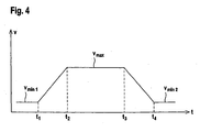
- Figure 4 shows the time course of such a target speed profile for the opening operation of the door drive 1.
- a delay phase in the time interval between t 3 and t 4 , within which the door drive 1 is braked with constant speed gradients from the speed v max to the speed v min2 .
- the door drive 1 is turned off in its upper end position by means of the limit switch 8.
- the velocities v min1 and v min2 are chosen to be the same.
- the desired speed profile for the closing operation corresponds to the shape of the speed profile according to FIG. 4. Only the absolute values for the desired speed values and the lengths of the phases defining times t 1 -t 4 can vary in absolute terms.
- the door drive 1 is accelerated within the predetermined acceleration phase , as shown for example in FIG. 4, from the speed V min1 to the speed V max . Subsequently, the door drive 1 is moved at a constant speed to its end position, the duration of the door drive 1 is detected here. In the computer unit 3, the time t 3 then calculated from this term, at which the deceleration phase is initiated. In this way, the desired speed profile is set both for the opening operation and for the closing operation.
- the speed of the door drive 1 is then regulated by means of the control unit 5 to the predetermined desired speed profile.
Landscapes
- Engineering & Computer Science (AREA)
- Human Computer Interaction (AREA)
- Manufacturing & Machinery (AREA)
- Physics & Mathematics (AREA)
- General Physics & Mathematics (AREA)
- Automation & Control Theory (AREA)
- Power-Operated Mechanisms For Wings (AREA)
- Elevator Door Apparatuses (AREA)
- Control Of Electric Motors In General (AREA)
Claims (17)
- Procédé de commande d'un entraînement électrique de porte ou de portail comprenant les étapes de procédé suivantes :- détermination de la variation dans le temps des couples de rotation de l'entraînement de porte ou de portail pendant une phase d'apprentissage pour chaque fois au moins un cycle d'ouverture et un cycle de fermeture,- déduction à partir des couples de rotation déterminés de couples de rotation maximums admissibles pour des zones prédéfinies à l'intérieur d'un cycle d'ouverture et de fermeture,- comparaison des couples de rotation actuels avec les couples de rotation maximums et comparaison des vitesses actuelles de l'entraînement de porte ou de portail avec des vitesses de consigne prédéfinies pendant le fonctionnement de l'entraînement de porte ou de portail,- augmentation de la vitesse actuelle de l'entraînement de porte ou de portail lorsqu'on arrive en dessous de la vitesse de consigne associée,- arrêt de l'entraînement de porte si le couple de rotation actuel dépasse le couple de rotation maximum associé.
- Procédé selon la revendication 1, caractérisé par le fait qu'un profil de vitesse de consigne est prédéfini chaque fois pour le cycle d'ouverture et le cycle de fermeture.
- Procédé selon la revendication 2, caractérisé par le fait que la vitesse actuelle est régulée, les valeurs de consigne de la boucle de régulation étant formées par les profils de vitesse de consigne.
- Procédé selon l'une des revendications 2 ou 3, caractérisé par le fait que les profils de vitesse de consigne sont définis par des paramètres de vitesse.
- Procédé selon la revendication 4, caractérisé par le fait que chaque profil de vitesse de consigne est formé par une phase d'accélération avec gradient de vitesse constant en vue de l'accélération d'une vitesse Vmin1 à une vitesse maximum Vmax, d'une phase suivante à vitesse constante Vmax et d'une phase de décélération ou de retardement avec gradient de vitesse constant en vue du ralentissement de la vitesse maximum Vmax à une vitesse Vmin2.
- Procédé selon la revendication 5, caractérisé par le fait que les vitesses Vmin1, Vmin2 et Vmax, les gradients de vitesse ainsi que la durée de chaque phase forment les paramètres de vitesse.
- Procédé selon l'une des revendications 5 ou 6, caractérisé par le fait que pour déterminer un profil de vitesse on effectue un essai ou cycle d'apprentissage au cours duquel l'entraînement de porte (1) est accéléré de la vitesse vmin1 à la vitesse maximum vmax pendant la phase d'accélération, l'entraînement de porte (1) étant déplacé dans sa position extrême à cette vitesse maximum vmax, et que l'on calcule le début de la phase de décélération ou de retardement à partir du temps de parcours de l'entraînement de porte (1).
- Procédé selon l'une des revendications 1 à 7, caractérisé par le fait que le cycle d'ouverture et le cycle de fermeture sont divisés chacun en zones de même durée.
- Procédé selon la revendication 8, caractérisé par le fait que le cycle de fermeture est divisé en plusieurs zones.
- Procédé selon l'une des revendications 8 ou 9, caractérisé par le fait qu'une zone est affectée au cycle d'ouverture.
- Procédé selon l'une des revendications 8 à 10, caractérisé par le fait que pendant le cycle d'apprentissage on détermine à partir des couples de rotation déterminés le couple de rotation maximum Dimax pour chaque zone i, et que l'on calcule pour chaque zone i en tant que couple de rotation maximum admissible la valeur seuil Si d'après Si = Dimax + Δ, Δ étant une constante positive.
- Dispositif pour commander un entraînement de porte avec le procédé selon l'une des revendications 1 à 11,
avec des moyens pour déterminer les couples de rotation de l'entraînement de porte (1),
avec des moyens pour déterminer les vitesses actuelles de l'entraînement de porte (1),
et avec une unité de calcul (3) dans laquelle on peut déterminer pendant un cycle d'apprentissage la variation dans le temps des couples de rotation de l'entraînement de porte (1) pour chaque fois au moins un cycle d'ouverture et un cycle de fermeture,
et dans laquelle on peut déduire à partir des couples de rotation déterminés des couples de rotation maximums admissibles pour des zones prédéfinies à l'intérieur d'un cycle d'ouverture et de fermeture,
avec une unité de mémoire (4) pour la mémorisation de vitesses de consigne prédéfinies pendant le fonctionnement de l'entraînement de porte ou de portail (1),
une instruction de commande permettant d'augmenter la vitesse actuelle de l'entraînement de porte (1) pouvant être générée par l'unité de calcul (3) si celle-ci devient inférieure à la vitesse de consigne associée pendant le fonctionnement de l'entraînement de porte (1),
et avec des moyens de commutation commandés par l'unité de calcul (3), une instruction de commutation permettant l'arrêt de l'entraînement de porte (1) pouvant être générée dans celle-ci si le couple de rotation actuel dépasse le couple de rotation maximum admissible pendant le fonctionnement de l'entraînement de porte (1). - Dispositif selon la revendication 12, caractérisé par le fait que l'entraînement de porte (1) comprend un moteur électrique.
- Dispositif selon la revendication 13, caractérisé par le fait que les moyens pour déterminer le couple de rotation comprennent un circuit de mesure permettant de déterminer l'intensité du courant du moteur électrique.
- Dispositif selon l'une des revendications 13 ou 14, caractérisé par le fait que les moyens pour déterminer la vitesse de l'entraînement de porte (1) comprennent un circuit de mesure permettant de déterminer la vitesse de rotation du moteur électrique.
- Dispositif selon l'une des revendications 12 à 15, caractérisé par le fait que l'unité de calcul (3) comprend une unité de régulation (5) pour réguler la vitesse de l'entraînement de porte (1).
- Dispositif selon l'une des revendications 12 à 16, caractérisé par le fait que l'entraînement de porte (1) comprend des interrupteurs de fin de course (8) en vue de son arrêt dans ses positions extrêmes.
Applications Claiming Priority (3)
| Application Number | Priority Date | Filing Date | Title |
|---|---|---|---|
| DE10310480 | 2003-03-11 | ||
| DE10310480A DE10310480B4 (de) | 2003-03-11 | 2003-03-11 | Verfahren und Vorrichtung zum Steuern eines Torantriebes |
| PCT/EP2004/001649 WO2004081681A1 (fr) | 2003-03-11 | 2004-02-20 | Procede et dispositif de commande d'un entrainement de porte |
Publications (2)
| Publication Number | Publication Date |
|---|---|
| EP1602014A1 EP1602014A1 (fr) | 2005-12-07 |
| EP1602014B1 true EP1602014B1 (fr) | 2006-10-04 |
Family
ID=32920706
Family Applications (1)
| Application Number | Title | Priority Date | Filing Date |
|---|---|---|---|
| EP04713046A Expired - Lifetime EP1602014B1 (fr) | 2003-03-11 | 2004-02-20 | Procede et dispositif de commande d'un entrainement de porte |
Country Status (14)
| Country | Link |
|---|---|
| US (1) | US7667425B2 (fr) |
| EP (1) | EP1602014B1 (fr) |
| CN (1) | CN100489712C (fr) |
| AT (1) | ATE341780T1 (fr) |
| AU (1) | AU2004219523B2 (fr) |
| CA (1) | CA2518062C (fr) |
| DE (2) | DE10310480B4 (fr) |
| ES (1) | ES2273223T3 (fr) |
| MX (1) | MXPA05009654A (fr) |
| PL (1) | PL213022B1 (fr) |
| PT (1) | PT1602014E (fr) |
| RU (1) | RU2316802C2 (fr) |
| WO (1) | WO2004081681A1 (fr) |
| ZA (1) | ZA200507267B (fr) |
Families Citing this family (16)
| Publication number | Priority date | Publication date | Assignee | Title |
|---|---|---|---|---|
| JP3620836B2 (ja) * | 2002-04-25 | 2005-02-16 | アイシン精機株式会社 | 開閉体の動作機構 |
| DE102005038878A1 (de) * | 2005-08-17 | 2007-02-22 | BSH Bosch und Siemens Hausgeräte GmbH | Gargerät |
| FR2898994B1 (fr) * | 2006-03-23 | 2008-06-06 | Somfy Sas | Procede de commande d'un volet roulant evitant l'application d'un effort trop important sur un obstacle |
| DE102007005881B3 (de) * | 2007-02-06 | 2008-07-31 | Marantec Antriebs- Und Steuerungstechnik Gmbh & Co. Kg | Verfahren zum Betrieb eines Torantriebes und Torantrieb |
| CN101477328B (zh) * | 2008-01-02 | 2010-10-20 | 台达电子工业股份有限公司 | 闸极驱动信号控制装置 |
| DE102009008369A1 (de) * | 2009-02-11 | 2010-08-12 | Continental Automotive Gmbh | Verfahren und Vorrichtung zur Pulsweiten-modulierten Ansteuerung eines elektrischen Antriebsmotors einer Verstelleinrichtung |
| US8341885B2 (en) * | 2010-09-23 | 2013-01-01 | Dynaco Europe | Door control system with obstacle detection |
| EP2813911A1 (fr) * | 2013-06-13 | 2014-12-17 | Assa Abloy Ab | Surveillance de porte |
| JP5969574B2 (ja) * | 2014-11-07 | 2016-08-17 | ファナック株式会社 | 過大負荷を検出するモータ制御装置 |
| US9984513B2 (en) | 2014-12-23 | 2018-05-29 | Palo Alto Resarch Center Incorporated | System and method for determining vehicle component conditions |
| CN105888435B (zh) * | 2016-05-12 | 2017-09-22 | 上汽通用汽车有限公司 | 汽车滑门速度控制方法和控制装置 |
| DK3475511T3 (da) | 2016-06-22 | 2021-06-21 | Assa Abloy Entrance Systems Ab | Fremgangsmåde til opsætning af en døroperatør og en døroperatør |
| CN107940669B (zh) * | 2017-11-03 | 2019-10-01 | 广东美的制冷设备有限公司 | 空调器的开合结构控制方法、空调器和可读存储介质 |
| WO2020221639A1 (fr) * | 2019-05-02 | 2020-11-05 | Assa Abloy Entrance Systems Ab | Système d'entrée basé sur une porte basculante à reconnaissance automatique de courbe de réduction de liaison |
| US12110730B2 (en) * | 2021-05-10 | 2024-10-08 | GM Global Technology Operations LLC | Vehicle closure cinching control systems and methods |
| US12252921B2 (en) | 2022-03-25 | 2025-03-18 | Y.E. Hub Armenia LLC | Robotic vehicle and a lid controller mechanism for a lid thereof |
Family Cites Families (17)
| Publication number | Priority date | Publication date | Assignee | Title |
|---|---|---|---|---|
| SU901439A1 (ru) * | 1980-05-16 | 1982-01-30 | Предприятие П/Я В-8094 | Устройство дл управлени приводами ворот двойных тамбуров |
| SU1553641A1 (ru) * | 1988-09-14 | 1990-03-30 | Московский Государственный Проектный Институт | Устройство дл аварийного переключени привода ворот при встрече с преп тствием |
| JPH07106860B2 (ja) * | 1989-04-26 | 1995-11-15 | 三菱電機株式会社 | エレベータのドアの制御装置 |
| US6404158B1 (en) * | 1992-04-22 | 2002-06-11 | Nartron Corporation | Collision monitoring system |
| DE4214998C2 (de) | 1992-05-06 | 1995-06-29 | Prettl Rolf | Torantrieb und Verfahren zum Betreiben eines Torantriebes |
| DE4331781C2 (de) * | 1993-09-18 | 2003-11-27 | Somfy Feinmech & Elektrotech | Steuervorrichtung für einen Antriebsmotor zum Bewegen eines entlang einer bestimmten Bahn zwischen zwei Endstellungen geführten Tors, insbesondere eines Garagentors |
| DE19504032C2 (de) * | 1994-05-02 | 1996-11-14 | Dorma Gmbh & Co Kg | Verfahren zur Regelung einer durch einen Antriebsmotor angetriebenen automatischen Tür |
| JP3834073B2 (ja) * | 1994-06-22 | 2006-10-18 | 株式会社安川電機 | 巻上・巻下機の停止方法 |
| DE19601359A1 (de) * | 1996-01-16 | 1997-07-17 | Fraunhofer Ges Forschung | Verfahren zum Steuern eines Gleichstromantriebs |
| DE19628238C2 (de) * | 1996-07-12 | 1999-01-07 | Berner Kurt | Verfahren zum Steuern eines elektrischen Torantriebes |
| DE19700828C5 (de) * | 1997-01-13 | 2013-06-06 | Geze Gmbh | Verfahren zum Betrieb einer automatischen Türanlage |
| US6249097B1 (en) * | 1997-11-21 | 2001-06-19 | Valeo Electrical Systems, Inc. | Optimum motor speed control system |
| JP4289570B2 (ja) | 1998-11-30 | 2009-07-01 | 三菱電機株式会社 | エレベータのドア制御装置 |
| WO2000042687A1 (fr) | 1999-01-18 | 2000-07-20 | Hörmann KG Antriebstechnik | Procede et commande pour commander un dispositif d'entrainement destine a une installation de fermeture d'un batiment ou d'une enceinte |
| US6051945A (en) * | 1999-01-25 | 2000-04-18 | Honda Giken Kogyo Kabushiki Kaisha | Anti-pinch safety system for vehicle closure device |
| EP1212666B1 (fr) | 1999-09-08 | 2003-03-26 | Hörmann KG Antriebstechnik | Procede permettant de reconnaitre des etats de fonctionnement d'un dispositif de fermeture qui peut etre mis en mouvement par un dispositif d'entrainement et qui est destine a un batiment ou un enclos |
| US6366042B1 (en) * | 2001-02-14 | 2002-04-02 | Motorola, Inc. | Anti-pinch power window system and method |
-
2003
- 2003-03-11 DE DE10310480A patent/DE10310480B4/de not_active Expired - Fee Related
-
2004
- 2004-02-20 MX MXPA05009654A patent/MXPA05009654A/es active IP Right Grant
- 2004-02-20 CA CA002518062A patent/CA2518062C/fr not_active Expired - Fee Related
- 2004-02-20 US US10/548,565 patent/US7667425B2/en not_active Expired - Fee Related
- 2004-02-20 ES ES04713046T patent/ES2273223T3/es not_active Expired - Lifetime
- 2004-02-20 RU RU2005127678/09A patent/RU2316802C2/ru not_active IP Right Cessation
- 2004-02-20 DE DE502004001673T patent/DE502004001673D1/de not_active Expired - Lifetime
- 2004-02-20 PL PL377529A patent/PL213022B1/pl unknown
- 2004-02-20 EP EP04713046A patent/EP1602014B1/fr not_active Expired - Lifetime
- 2004-02-20 PT PT04713046T patent/PT1602014E/pt unknown
- 2004-02-20 AU AU2004219523A patent/AU2004219523B2/en not_active Ceased
- 2004-02-20 CN CN200480006661.XA patent/CN100489712C/zh not_active Expired - Fee Related
- 2004-02-20 AT AT04713046T patent/ATE341780T1/de active
- 2004-02-20 WO PCT/EP2004/001649 patent/WO2004081681A1/fr not_active Ceased
-
2005
- 2005-09-09 ZA ZA200507267A patent/ZA200507267B/xx unknown
Also Published As
| Publication number | Publication date |
|---|---|
| AU2004219523B2 (en) | 2008-12-18 |
| CN1759356A (zh) | 2006-04-12 |
| AU2004219523A1 (en) | 2004-09-23 |
| US20060255757A1 (en) | 2006-11-16 |
| ZA200507267B (en) | 2007-04-25 |
| CA2518062A1 (fr) | 2004-09-23 |
| DE502004001673D1 (de) | 2006-11-16 |
| DE10310480B4 (de) | 2006-10-12 |
| EP1602014A1 (fr) | 2005-12-07 |
| PT1602014E (pt) | 2007-01-31 |
| RU2316802C2 (ru) | 2008-02-10 |
| CN100489712C (zh) | 2009-05-20 |
| MXPA05009654A (es) | 2005-10-20 |
| ES2273223T3 (es) | 2007-05-01 |
| US7667425B2 (en) | 2010-02-23 |
| DE10310480A1 (de) | 2004-09-30 |
| WO2004081681A1 (fr) | 2004-09-23 |
| CA2518062C (fr) | 2008-04-15 |
| ATE341780T1 (de) | 2006-10-15 |
| PL213022B1 (pl) | 2012-12-31 |
| RU2005127678A (ru) | 2006-06-10 |
| PL377529A1 (pl) | 2006-02-06 |
Similar Documents
| Publication | Publication Date | Title |
|---|---|---|
| EP1602014B1 (fr) | Procede et dispositif de commande d'un entrainement de porte | |
| EP1624772B1 (fr) | Procede pour entrainer une partie de meuble mobile | |
| EP1075723B1 (fr) | Dispositif de fermeture avec fonction de securite | |
| EP1332538B1 (fr) | Procede pour commander un processus de reglage d'une partie | |
| EP0966782A1 (fr) | Procede de commande et de regulation electriques du deplacement d'unites actionnees electriquement | |
| DE19632910C2 (de) | Verfahren zum berührungslosen Anfahren der unteren Anschlagsposition einer fremdkraftbetätigten Fensterscheibe eines Kraftfahrzeugs | |
| EP0910883B1 (fr) | Procede de commande de la fermeture de dispositifs de fermeture pourvus d'au moins une partie deplacee par moteur electrique | |
| DE102009014808A1 (de) | Verfahren und Vorrichtung zum Ansteuern eines eine Ansprechverzögerung aufweisenden Steuerelements einer Antriebseinrichtung | |
| DE102005000753A1 (de) | Steuerungsvorrichtung einer Verstelleinrichtung eines Kraftfahrzeugs, insbesondere eines Kraftfahrzeugfensterhebers | |
| EP2834913B1 (fr) | Procédé et dispositif de freinage électrodynamique d'un moteur universel | |
| DE102009035449B3 (de) | Verfahren und Vorrichtung zur zeitgesteuerten Einklemmerkennung | |
| EP0561361B1 (fr) | Procédé et dispositif pour commander des actionneurs de porte | |
| DE19628238A1 (de) | Verfahren zum Steuern eines elektrischen Torantriebes | |
| DE19700828C5 (de) | Verfahren zum Betrieb einer automatischen Türanlage | |
| EP1447729B1 (fr) | Méthode de commande d'orientation d'une broche | |
| DE102007004445C5 (de) | Antriebsvorrichtung | |
| EP2837090B1 (fr) | Procédé et dispositif de freinage électrodynamique d'un moteur universel | |
| WO2004021094A1 (fr) | Determination de masse pour commandes automatiques de porte coulissante et d'ascenseur | |
| EP0692059B1 (fr) | Procede permettant de faire fonctionner une porte a tambour | |
| EP1149451B2 (fr) | Procede et commande pour commander un dispositif d'entrainement destine a une installation de fermeture d'un batiment ou d'une enceinte | |
| EP3291028B1 (fr) | Transstockeur et procédé de fonctionnement d'un transstockeur | |
| DE102012016302A1 (de) | Einklemmschutzverfahren | |
| DE2954670C2 (en) | Electrically powered vehicle window drive | |
| DE102004002127A1 (de) | Verfahren und Vorrichtung sowie Steuerungsprogramm und Computerprogramm-Produkt zur Steuerung einer elektrischen Antriebseinrichtung | |
| DE102006059446A1 (de) | Verfahren und Einrichtung zum Erfassen des Vorliegens eines mechanischen Spiels |
Legal Events
| Date | Code | Title | Description |
|---|---|---|---|
| PUAI | Public reference made under article 153(3) epc to a published international application that has entered the european phase |
Free format text: ORIGINAL CODE: 0009012 |
|
| 17P | Request for examination filed |
Effective date: 20050723 |
|
| AK | Designated contracting states |
Kind code of ref document: A1 Designated state(s): AT BE BG CH CY CZ DE DK EE ES FI FR GB GR HU IE IT LI LU MC NL PT RO SE SI SK TR |
|
| AX | Request for extension of the european patent |
Extension state: AL LT LV MK |
|
| GRAP | Despatch of communication of intention to grant a patent |
Free format text: ORIGINAL CODE: EPIDOSNIGR1 |
|
| DAX | Request for extension of the european patent (deleted) | ||
| GRAS | Grant fee paid |
Free format text: ORIGINAL CODE: EPIDOSNIGR3 |
|
| GRAA | (expected) grant |
Free format text: ORIGINAL CODE: 0009210 |
|
| RBV | Designated contracting states (corrected) |
Designated state(s): AT BE CH DE ES FR GB GR HU IT LI NL PT TR |
|
| AK | Designated contracting states |
Kind code of ref document: B1 Designated state(s): AT BE CH DE ES FR GB GR HU IT LI NL PT TR |
|
| PG25 | Lapsed in a contracting state [announced via postgrant information from national office to epo] |
Ref country code: NL Free format text: LAPSE BECAUSE OF FAILURE TO SUBMIT A TRANSLATION OF THE DESCRIPTION OR TO PAY THE FEE WITHIN THE PRESCRIBED TIME-LIMIT Effective date: 20061004 |
|
| REG | Reference to a national code |
Ref country code: GB Ref legal event code: FG4D Free format text: NOT ENGLISH |
|
| GBT | Gb: translation of ep patent filed (gb section 77(6)(a)/1977) |
Effective date: 20061004 |
|
| REG | Reference to a national code |
Ref country code: CH Ref legal event code: EP Ref country code: CH Ref legal event code: NV Representative=s name: ROTTMANN, ZIMMERMANN + PARTNER AG |
|
| REF | Corresponds to: |
Ref document number: 502004001673 Country of ref document: DE Date of ref document: 20061116 Kind code of ref document: P |
|
| REG | Reference to a national code |
Ref country code: GR Ref legal event code: EP Ref document number: 20060404142 Country of ref document: GR |
|
| REG | Reference to a national code |
Ref country code: PT Ref legal event code: SC4A Free format text: AVAILABILITY OF NATIONAL TRANSLATION Effective date: 20061120 |
|
| REG | Reference to a national code |
Ref country code: HU Ref legal event code: AG4A Ref document number: E001054 Country of ref document: HU |
|
| ET | Fr: translation filed | ||
| NLV1 | Nl: lapsed or annulled due to failure to fulfill the requirements of art. 29p and 29m of the patents act | ||
| REG | Reference to a national code |
Ref country code: ES Ref legal event code: FG2A Ref document number: 2273223 Country of ref document: ES Kind code of ref document: T3 |
|
| NLXE | Nl: other communications concerning ep-patents (part 3 heading xe) |
Free format text: A REQUEST FOR RESTORATION TO THE PRIOR STATE (ARTICLE 23 OF THE PATENTS ACT 1995) HAS BEEN FILED ON 20070405 |
|
| PLBE | No opposition filed within time limit |
Free format text: ORIGINAL CODE: 0009261 |
|
| STAA | Information on the status of an ep patent application or granted ep patent |
Free format text: STATUS: NO OPPOSITION FILED WITHIN TIME LIMIT |
|
| 26N | No opposition filed |
Effective date: 20070705 |
|
| NLXE | Nl: other communications concerning ep-patents (part 3 heading xe) |
Free format text: THE REQUEST FOR RESTORATION TO THE PRIOR STATE, AS PROVIDED FOR IN ARTICLE 23 OF THE PATENTS ACT 1995 (SEE PUBLICATION IN HEADING XE OF THE PATENT BULLETIN OF 20070601) HAS BEEN GRANTED; THE RESTORATION OF THE PATENT HAS BEEN ENTERED IN THE PATENT REGISTER. |
|
| PGFP | Annual fee paid to national office [announced via postgrant information from national office to epo] |
Ref country code: HU Payment date: 20110225 Year of fee payment: 8 |
|
| PGFP | Annual fee paid to national office [announced via postgrant information from national office to epo] |
Ref country code: PT Payment date: 20110217 Year of fee payment: 8 Ref country code: CH Payment date: 20110222 Year of fee payment: 8 |
|
| REG | Reference to a national code |
Ref country code: CH Ref legal event code: PFA Owner name: SOMMER ANTRIEBS- UND FUNKTECHNIK GMBH Free format text: SOMMER ANTRIEBS- UND FUNKTECHNIK GMBH#HANS-BOECKLER-STRASSE 21-27#73230 KIRCHHEIM/TECK (DE) -TRANSFER TO- SOMMER ANTRIEBS- UND FUNKTECHNIK GMBH#HANS-BOECKLER-STRASSE 21-27#73230 KIRCHHEIM/TECK (DE) |
|
| PGFP | Annual fee paid to national office [announced via postgrant information from national office to epo] |
Ref country code: TR Payment date: 20120213 Year of fee payment: 9 |
|
| PGFP | Annual fee paid to national office [announced via postgrant information from national office to epo] |
Ref country code: GR Payment date: 20120228 Year of fee payment: 9 Ref country code: BE Payment date: 20120329 Year of fee payment: 9 Ref country code: GB Payment date: 20120221 Year of fee payment: 9 Ref country code: IT Payment date: 20120221 Year of fee payment: 9 |
|
| PGFP | Annual fee paid to national office [announced via postgrant information from national office to epo] |
Ref country code: NL Payment date: 20120228 Year of fee payment: 9 |
|
| REG | Reference to a national code |
Ref country code: PT Ref legal event code: MM4A Free format text: LAPSE DUE TO NON-PAYMENT OF FEES Effective date: 20120820 |
|
| REG | Reference to a national code |
Ref country code: CH Ref legal event code: PL |
|
| PG25 | Lapsed in a contracting state [announced via postgrant information from national office to epo] |
Ref country code: LI Free format text: LAPSE BECAUSE OF NON-PAYMENT OF DUE FEES Effective date: 20120229 Ref country code: CH Free format text: LAPSE BECAUSE OF NON-PAYMENT OF DUE FEES Effective date: 20120229 |
|
| PG25 | Lapsed in a contracting state [announced via postgrant information from national office to epo] |
Ref country code: HU Free format text: LAPSE BECAUSE OF NON-PAYMENT OF DUE FEES Effective date: 20120221 Ref country code: PT Free format text: LAPSE BECAUSE OF NON-PAYMENT OF DUE FEES Effective date: 20120820 |
|
| PGFP | Annual fee paid to national office [announced via postgrant information from national office to epo] |
Ref country code: AT Payment date: 20120213 Year of fee payment: 9 |
|
| PGFP | Annual fee paid to national office [announced via postgrant information from national office to epo] |
Ref country code: DE Payment date: 20130216 Year of fee payment: 10 Ref country code: FR Payment date: 20130301 Year of fee payment: 10 Ref country code: ES Payment date: 20130227 Year of fee payment: 10 |
|
| BERE | Be: lapsed |
Owner name: SOMMER ANTRIEBS- UND FUNKTECHNIK G.M.B.H. Effective date: 20130228 |
|
| REG | Reference to a national code |
Ref country code: NL Ref legal event code: V1 Effective date: 20130901 |
|
| REG | Reference to a national code |
Ref country code: AT Ref legal event code: MM01 Ref document number: 341780 Country of ref document: AT Kind code of ref document: T Effective date: 20130228 |
|
| REG | Reference to a national code |
Ref country code: GR Ref legal event code: ML Ref document number: 20060404142 Country of ref document: GR Effective date: 20130904 |
|
| GBPC | Gb: european patent ceased through non-payment of renewal fee |
Effective date: 20130220 |
|
| PG25 | Lapsed in a contracting state [announced via postgrant information from national office to epo] |
Ref country code: AT Free format text: LAPSE BECAUSE OF NON-PAYMENT OF DUE FEES Effective date: 20130228 Ref country code: GR Free format text: LAPSE BECAUSE OF NON-PAYMENT OF DUE FEES Effective date: 20130904 Ref country code: NL Free format text: LAPSE BECAUSE OF FAILURE TO SUBMIT A TRANSLATION OF THE DESCRIPTION OR TO PAY THE FEE WITHIN THE PRESCRIBED TIME-LIMIT Effective date: 20130901 |
|
| PG25 | Lapsed in a contracting state [announced via postgrant information from national office to epo] |
Ref country code: BE Free format text: LAPSE BECAUSE OF NON-PAYMENT OF DUE FEES Effective date: 20130228 Ref country code: GB Free format text: LAPSE BECAUSE OF NON-PAYMENT OF DUE FEES Effective date: 20130220 |
|
| PG25 | Lapsed in a contracting state [announced via postgrant information from national office to epo] |
Ref country code: TR Free format text: LAPSE BECAUSE OF NON-PAYMENT OF DUE FEES Effective date: 20130220 |
|
| REG | Reference to a national code |
Ref country code: DE Ref legal event code: R119 Ref document number: 502004001673 Country of ref document: DE |
|
| REG | Reference to a national code |
Ref country code: FR Ref legal event code: ST Effective date: 20141031 |
|
| REG | Reference to a national code |
Ref country code: DE Ref legal event code: R119 Ref document number: 502004001673 Country of ref document: DE Effective date: 20140902 |
|
| PG25 | Lapsed in a contracting state [announced via postgrant information from national office to epo] |
Ref country code: FR Free format text: LAPSE BECAUSE OF NON-PAYMENT OF DUE FEES Effective date: 20140228 Ref country code: DE Free format text: LAPSE BECAUSE OF NON-PAYMENT OF DUE FEES Effective date: 20140902 |
|
| PG25 | Lapsed in a contracting state [announced via postgrant information from national office to epo] |
Ref country code: IT Free format text: LAPSE BECAUSE OF NON-PAYMENT OF DUE FEES Effective date: 20140220 |
|
| PG25 | Lapsed in a contracting state [announced via postgrant information from national office to epo] |
Ref country code: ES Free format text: LAPSE BECAUSE OF NON-PAYMENT OF DUE FEES Effective date: 20140221 |