EP3292040B1 - Unterwasserfahrzeug zur inspektion einer unterwasserstruktur in einem gewässer und zugehöriges verfahren - Google Patents
Unterwasserfahrzeug zur inspektion einer unterwasserstruktur in einem gewässer und zugehöriges verfahren Download PDFInfo
- Publication number
- EP3292040B1 EP3292040B1 EP15763076.5A EP15763076A EP3292040B1 EP 3292040 B1 EP3292040 B1 EP 3292040B1 EP 15763076 A EP15763076 A EP 15763076A EP 3292040 B1 EP3292040 B1 EP 3292040B1
- Authority
- EP
- European Patent Office
- Prior art keywords
- support body
- vehicle
- subsea structure
- probe
- cathodic protection
- Prior art date
- Legal status (The legal status is an assumption and is not a legal conclusion. Google has not performed a legal analysis and makes no representation as to the accuracy of the status listed.)
- Active
Links
Images


Classifications
-
- B—PERFORMING OPERATIONS; TRANSPORTING
- B63—SHIPS OR OTHER WATERBORNE VESSELS; RELATED EQUIPMENT
- B63C—LAUNCHING, HAULING-OUT, OR DRY-DOCKING OF VESSELS; LIFE-SAVING IN WATER; EQUIPMENT FOR DWELLING OR WORKING UNDER WATER; MEANS FOR SALVAGING OR SEARCHING FOR UNDERWATER OBJECTS
- B63C11/00—Equipment for dwelling or working underwater; Means for searching for underwater objects
- B63C11/52—Tools specially adapted for working underwater, not otherwise provided for
-
- B—PERFORMING OPERATIONS; TRANSPORTING
- B63—SHIPS OR OTHER WATERBORNE VESSELS; RELATED EQUIPMENT
- B63G—OFFENSIVE OR DEFENSIVE ARRANGEMENTS ON VESSELS; MINE-LAYING; MINE-SWEEPING; SUBMARINES; AIRCRAFT CARRIERS
- B63G8/00—Underwater vessels, e.g. submarines; Equipment specially adapted therefor
- B63G8/001—Underwater vessels adapted for special purposes, e.g. unmanned underwater vessels; Equipment specially adapted therefor, e.g. docking stations
-
- C—CHEMISTRY; METALLURGY
- C23—COATING METALLIC MATERIAL; COATING MATERIAL WITH METALLIC MATERIAL; CHEMICAL SURFACE TREATMENT; DIFFUSION TREATMENT OF METALLIC MATERIAL; COATING BY VACUUM EVAPORATION, BY SPUTTERING, BY ION IMPLANTATION OR BY CHEMICAL VAPOUR DEPOSITION, IN GENERAL; INHIBITING CORROSION OF METALLIC MATERIAL OR INCRUSTATION IN GENERAL
- C23F—NON-MECHANICAL REMOVAL OF METALLIC MATERIAL FROM SURFACE; INHIBITING CORROSION OF METALLIC MATERIAL OR INCRUSTATION IN GENERAL; MULTI-STEP PROCESSES FOR SURFACE TREATMENT OF METALLIC MATERIAL INVOLVING AT LEAST ONE PROCESS PROVIDED FOR IN CLASS C23 AND AT LEAST ONE PROCESS COVERED BY SUBCLASS C21D OR C22F OR CLASS C25
- C23F13/00—Inhibiting corrosion of metals by anodic or cathodic protection
- C23F13/02—Inhibiting corrosion of metals by anodic or cathodic protection cathodic; Selection of conditions, parameters or procedures for cathodic protection, e.g. of electrical conditions
- C23F13/06—Constructional parts, or assemblies of cathodic-protection apparatus
- C23F13/08—Electrodes specially adapted for inhibiting corrosion by cathodic protection; Manufacture thereof; Conducting electric current thereto
- C23F13/22—Monitoring arrangements therefor
-
- B—PERFORMING OPERATIONS; TRANSPORTING
- B63—SHIPS OR OTHER WATERBORNE VESSELS; RELATED EQUIPMENT
- B63G—OFFENSIVE OR DEFENSIVE ARRANGEMENTS ON VESSELS; MINE-LAYING; MINE-SWEEPING; SUBMARINES; AIRCRAFT CARRIERS
- B63G8/00—Underwater vessels, e.g. submarines; Equipment specially adapted therefor
- B63G8/001—Underwater vessels adapted for special purposes, e.g. unmanned underwater vessels; Equipment specially adapted therefor, e.g. docking stations
- B63G2008/002—Underwater vessels adapted for special purposes, e.g. unmanned underwater vessels; Equipment specially adapted therefor, e.g. docking stations unmanned
- B63G2008/004—Underwater vessels adapted for special purposes, e.g. unmanned underwater vessels; Equipment specially adapted therefor, e.g. docking stations unmanned autonomously operating
-
- B—PERFORMING OPERATIONS; TRANSPORTING
- B63—SHIPS OR OTHER WATERBORNE VESSELS; RELATED EQUIPMENT
- B63G—OFFENSIVE OR DEFENSIVE ARRANGEMENTS ON VESSELS; MINE-LAYING; MINE-SWEEPING; SUBMARINES; AIRCRAFT CARRIERS
- B63G8/00—Underwater vessels, e.g. submarines; Equipment specially adapted therefor
- B63G8/001—Underwater vessels adapted for special purposes, e.g. unmanned underwater vessels; Equipment specially adapted therefor, e.g. docking stations
- B63G2008/002—Underwater vessels adapted for special purposes, e.g. unmanned underwater vessels; Equipment specially adapted therefor, e.g. docking stations unmanned
- B63G2008/005—Underwater vessels adapted for special purposes, e.g. unmanned underwater vessels; Equipment specially adapted therefor, e.g. docking stations unmanned remotely controlled
-
- B—PERFORMING OPERATIONS; TRANSPORTING
- B63—SHIPS OR OTHER WATERBORNE VESSELS; RELATED EQUIPMENT
- B63G—OFFENSIVE OR DEFENSIVE ARRANGEMENTS ON VESSELS; MINE-LAYING; MINE-SWEEPING; SUBMARINES; AIRCRAFT CARRIERS
- B63G8/00—Underwater vessels, e.g. submarines; Equipment specially adapted therefor
- B63G8/001—Underwater vessels adapted for special purposes, e.g. unmanned underwater vessels; Equipment specially adapted therefor, e.g. docking stations
- B63G2008/002—Underwater vessels adapted for special purposes, e.g. unmanned underwater vessels; Equipment specially adapted therefor, e.g. docking stations unmanned
- B63G2008/005—Underwater vessels adapted for special purposes, e.g. unmanned underwater vessels; Equipment specially adapted therefor, e.g. docking stations unmanned remotely controlled
- B63G2008/007—Underwater vessels adapted for special purposes, e.g. unmanned underwater vessels; Equipment specially adapted therefor, e.g. docking stations unmanned remotely controlled by means of a physical link to a base, e.g. wire, cable or umbilical
-
- C—CHEMISTRY; METALLURGY
- C23—COATING METALLIC MATERIAL; COATING MATERIAL WITH METALLIC MATERIAL; CHEMICAL SURFACE TREATMENT; DIFFUSION TREATMENT OF METALLIC MATERIAL; COATING BY VACUUM EVAPORATION, BY SPUTTERING, BY ION IMPLANTATION OR BY CHEMICAL VAPOUR DEPOSITION, IN GENERAL; INHIBITING CORROSION OF METALLIC MATERIAL OR INCRUSTATION IN GENERAL
- C23F—NON-MECHANICAL REMOVAL OF METALLIC MATERIAL FROM SURFACE; INHIBITING CORROSION OF METALLIC MATERIAL OR INCRUSTATION IN GENERAL; MULTI-STEP PROCESSES FOR SURFACE TREATMENT OF METALLIC MATERIAL INVOLVING AT LEAST ONE PROCESS PROVIDED FOR IN CLASS C23 AND AT LEAST ONE PROCESS COVERED BY SUBCLASS C21D OR C22F OR CLASS C25
- C23F2213/00—Aspects of inhibiting corrosion of metals by anodic or cathodic protection
- C23F2213/30—Anodic or cathodic protection specially adapted for a specific object
- C23F2213/31—Immersed structures, e.g. submarine structures
Definitions
- the present invention concerns an underwater vehicle for inspection of a subsea structure, according to the preamble of claim 1.
- Such a vehicle is designed in particular for inspecting rigid pipes transporting hydrocarbons.
- the pipes are usually located at the seabed.
- the aim of the inspection is to detect potential defects resulting from corrosion of the pipes.
- ROV remotely operated vehicle
- the ROV is controlled from the surface to follow the subsea structure.
- a deployable articulated arm extends from a side of the ROV to place a first proximity cathodic protection probe very close to the pipe to be sensed.
- a second remote cathodic protection probe is immersed into the body of water from the surface facility, at a distance from the surface facility to obtain a reference measurement outside the electrical field.
- a voltage difference between the proximity probe and the remote probe is measured along the pipe. From time to time, the ROV is touching directly the pipe (at an anode connection for instance), in order to calibrate the voltage difference between the electrode close to the pipe and the one in shallow water.
- the method allows a precise corrosion measurement of the surface of the pipe. Nevertheless, the method is time consuming, expensive and requires complex equipment such as a ROV and an associated surface assembly connected to the ROV.
- US 2014/0230713 discloses an underwater mobile inspection apparatus which is able to cruise autonomously above a pipeline.
- the apparatus comprises an articulated arm equipped with a proximity cathodic protection probe.
- the articulated arm is attached to a side of the vehicle.
- the proximity cathodic protection probe is carried on a cart which rolls on the pipeline.
- the cart is deployed from the articulated arm, creating a strong drag when cruising the inspection apparatus above the pipe and generates high friction on the pipeline.
- the inspection apparatus can only be operated at very slow speeds, with a substantial risk of damaging the surface of the pipeline.
- One aim of the invention is to obtain an underwater vehicle suitable for corrosion inspection of a subsea structure, the vehicle being able to be operated at a high speed above the subsea structure.
- the subject-matter of the invention is an underwater vehicle according to claim 1.
- the underwater vehicle according to the invention may comprise one or more of the features of claims 2 to 12, taken solely or according to any possible technical combination or the following feature:
- the invention also relates to a method for inspecting a subsea structure, according to claim 13.
- the method according to the invention may comprise one or more of the features of claims 14 or 15.
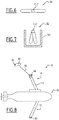
- a first underwater vehicle 10 according to the invention is shown schematically in figures 1 and 2 .
- the vehicle 10 is an autonomous underwater vehicle able to autonomously cruise in a body of water 16.
- the autonomous underwater vehicle 10 is for inspecting a subsea structure 12 in an installation 14 of production of hydrocarbons through a body of water 16.
- the subsea structure 12 comprises for example at least a production well 18 bored in the seabed 20 of the body of water 16, and at least a rigid metallic pipe 22 connecting the well 18 to a storage and/or transportation assembly comprising at least a riser and:or a subsea to shore pipeline (not shown).
- the subsea structure 12 can also be any subsea structure protected against corrosion by galvanic anode or impressed current cathodic protection.
- Example of such structures may be risers, rigid or flexible pipelines, buoyancy tanks, mooring lines, etc.
- the installation 14 preferably also comprises a surface assembly 24 floating or fixed at the surface of the body of water 16.
- the body of water 16 is for example a sea, an ocean, a lake and/or a river.
- the depth of the body of water 16, taken in the vicinity of the inspected subsea structure 12 is for example comprised between 10 m and 5000 m.
- the transportation pipe 22 of the subsea structure is a metallic pipe covered partially or entirely with a protective coating.
- the pipe 22 is preferably provided with an anodic protection comprising sacrificial anodes 26 distributed along the pipe 22.
- the sacrificial anodes 26 are able to corrode to compensate for the corrosion of potential defects 28 located at the coating of the pipe 22.
- a current flow 29 (see figure 2 ) locally establishes at the surface of the pipe 22 between the sacrificial anodes 26 and the defects 28.
- the application of the current flow 29 produces a decrease in the electrochemical potential of the subsea structure 12 and by a local electric field in the water around the subsea structure 12.
- the local electric field is generally distributed between the anode 26 and the bare metal at the location of the defect 28.
- the efficiency of the protection is a function of the density of cathodic current and hence of the electrode potential obtained.
- the electrode potential can therefore be measured to assess the efficiency of the protection.
- the autonomous underwater vehicle 10 comprises a support body 30, a lower proximity sensor 32, deployable downwardly from the support body 30 to measure a first reference potential in the vicinity of the subsea structure 12, in the cathodic protection zone and an upper remote sensor 34, deployable upwardly from the support body 30 to measure a second reference potential away from the subsea structure 12 and from the cathodic protection zone.
- the autonomous underwater vehicle 10 is configured to cruise autonomously in the body of water 16, without physical link to a surface installation above the subsea structure 12. The risk of damaging the subsea structure 12 or the vehicle 10 is thus minimized.
- the support body 30 comprises a profiled hull 36, carrying the lower proximity sensor 32 and the upper remote sensor 34, a propeller 38, and a power source 40 connected to the propeller 38.
- the support body 30 further comprises at least a mobile control surface 42 and a control unit 44, able to control the power source 40 to control the propeller 38 and the mobile control surface(s) 42 to drive the vehicle 30 along the predefined path.
- the support body 30 comprises at least a position probe 46 able to sense the depth and/or horizontal location of the autonomous underwater vehicle 10.
- the support body 30 may comprise a wireless communication unit 50 able to communicate with the surface installation 24 to receive instructions from the surface installation 24 and/or to transmit data stored in the data storage unit 48 to the surface installation 24.
- the hull 36 has for example a torpedo shape, with a tapering nose 52 and an enlarged tail 54.
- the propeller 38 is for example located at the tail 54.
- the support body 30 When the propeller 38 is active, the support body 30 is able to cruise along the subsea structure 12 with a speed which can be more than 0.5 knots (i.e., 0.9 km/h), and which can be comprised between 0.5 knots and 2.5 knots (between 0.9 km/h and 4.6 km/h).
- a speed which can be more than 0.5 knots (i.e., 0.9 km/h), and which can be comprised between 0.5 knots and 2.5 knots (between 0.9 km/h and 4.6 km/h).
- the length of the hull 36, taken along a longitudinal axis A-A' of the support body 30 is for example greater than 4 m and comprised between 4 m and 10 m.
- the maximum transverse dimension of the hull 36, taken perpendicularly to the longitudinal axis A-A' is for example higher than 0.3 m and comprised between 0.3 m and 2 m.
- the lower proximity sensor 32 comprises a lower cathodic protection probe 60 and a deployable arm 62 carrying the lower cathodic protection probe 60.
- the lower proximity sensor 32 further comprises a lowering mechanism 64 able to move the deployable arm 62 between an upper retracted position along the support body 30 and a lower deployed position, protruding from the support body 30 towards the subsea structure 12.
- the lower proximity sensor 32 advantageously comprises an inclination probe 66, able to determine the angular inclination of the arm 32, with regard to the support body 30.
- the lower cathodic protection probe 60 comprises a first measurement electrode.
- the electrode generally comprises a metal wire immersed in a specific electrolytic solution.
- the electrolytic solution is placed into contact with the water through an orifice.
- the first measurement electrode is for example an Ag/AgCI or a Zinc reference electrode.
- the cathodic protection probe 60 has for example a weight comprised between 1 kg and 2 kg in air, a diameter comprised between 20 mm and 100 mm, and a length comprised between 300 mm and 600 mm.
- the deployable arm 62 is here made of a rigid rod 68 extending between a front end mounted on the support body 30, and a back end, able to freely deploy in the body of water 16 towards the subsea structure 12.
- the arm 62 is pivotably mounted on the support body 30 around a transverse horizontal axis B-B'.
- the deployable arm 62 is able to pivot from the retracted position to the deployed position, the free end of the rod 68 moving away from the hull 36, while the front end of the rod 68 remains in a globally invariant position.
- the lower cathodic protection probe 60 is fixed on the deployable arm 62, preferably at the free end or in the vicinity of the free end.
- the lowering mechanism 64 is able to move the deployable arm 62 between the retracted position and the deployed position. It comprises for example a spring-loaded member, able to generate a permanent spring force on the deployable arm 62 to return it in the retracted position.
- the lowering mechanism 64 also comprises an actuating member, able to overcome the spring force of the spring-loaded member to move the arm 62 towards the deployed position.
- the actuating member is also able to maintain the arm 62 in any angular position between the retracted position and the deployed position as shown in figure 2 .
- the lower proximity sensor 30 is located below the support body 30 in the retracted position and also in the deployed position, as well as in any position between the retracted position and the deployed position.
- the deployable arm 62 in the retracted position, extends longitudinally against the lower surface of the hull 36 or in a housing provided in the hull 36.
- the drag of the deployable arm 62 is minimal.
- the arm 68 extends for example perpendicularly to the longitudinal axis A-A'.
- the arm 62 is preferably profiled.
- it comprises a tapered form, having a tapered longitudinal front edge 70 and lateral extensions 72, defining concave longitudinal surfaces.
- internal water circulation passages 74 are advantageously provided longitudinally along the arm 62.
- the passages 74 open at the front end and at the back end of the arm 62 to allow longitudinal circulation of water through the arm 62.
- the arm 62 has a fin shape.
- the lateral extensions 72 are retractable around an axis defined for example by the edge 70, to further reduce the drag when the arm 62 is deployed.
- the arm 62 is not made of a single piece. It is made for example of a telescoping rod comprising a plurality of telescoping parts with a cable carrier able to control the length of the arm 62.
- the inclination probe 66 is connected to the control unit 44.
- the control unit 44 is then able to control the lowering mechanism 64 to maintain a predetermined altitude of the free end of the arm 62 with regard to the subsea structure 12, based on the inclination data received from the inclination probe 66 and the AUV altitude obtained from probe 46.
- the length of the arm 62 is preferably between 1 m to 2.5 m, and preferably between 1.5 to 2 m, to be able to extend sufficiently from the profiled hull 36 towards the subsea structure 12 while maintaining the support body 30 at a sufficient distance of the subsea structure 12.
- the upper remote sensor 34 comprises an upper cathodic protection probe 80, a deployable fish 82 carrying the upper cathodic protection probe 80, and an upper deployment mechanism 84 for deploying the deployable fish 82 away from the support body 30.
- the upper remote sensor 34 further comprises a position probe 86 for determining the relative position of the deployable fish 82 with regard to the support body.
- the position probe 86 is connected to the control unit 44 for controlling the deployment of the deployable fish 82 as a function of the data received from the position probe 86.
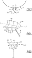
- the deployable fish 82 has a profiled shape. As shown in figure 4 , it comprises a lower longitudinal fin 90, and two lateral wings 92A, 92B protruding laterally from the top of the lower fin 90.
- the width W1 of the deployable fish 82 in the region of the lateral wings 92A, 92B, taken in projection in a plane perpendicular to a longitudinal axis C-C' of the fish is greater than the width W2 of the deployable fish 82 taken in the region of the lower fin 90.
- the lower fin 90 and the wings 92A, 92B delimit two lateral longitudinal concave lifting surfaces 94, located below the wings 92A, 92B, able to lift the fish 82 when the fish 82 moves longitudinally in the body of water.
- the wings 92A, 92B also delimit an upper concave surface 95, located above the wings 92A, 92B, able to stabilize the fish 82 when moving longitudinally along axis C-C'.
- the wings 92A, 92B are permanently deployed away from the central part 90.
- the wings 92A, 92B are retractable by rotation along the longitudinal axis C-C' to reduce the size of the fish 82 when it is introduced inside the release/capture mechanism 100.
- the upper deployment mechanism 84 comprises at least a line 96 mechanically and electrically connecting the fish 82 to the support body 30, a winch 98 able to unwind/wind up the line 96 to let the fish 82 move between an expanded position shown in figure 2 and a retracted position against the support body 30.
- the upper deployment mechanism advantageously comprises a release/capture mechanism 100 of the fish 82 to selectively maintain it against the support body 30 or release it.
- the release/capture mechanism 100 comprises at least a funnel 102, able to guide the fish 82 towards its retracted position.
- the upper cathodic protection probe 80 has also a reference electrode as described above, e.g. a zinc or Ag/AgCI reference electrode. It has a diameter comprised between 20 mm and 60 mm, and a length comprised between 100 mm and 200 mm. Its weight is comprised between 0,1 kg and 5 kg.
- a reference electrode as described above, e.g. a zinc or Ag/AgCI reference electrode. It has a diameter comprised between 20 mm and 60 mm, and a length comprised between 100 mm and 200 mm. Its weight is comprised between 0,1 kg and 5 kg.
- the line 96 is made of a tether comprising an insulation sheath, and an inner conductive core able to carry data collected by the upper cathodic protection reference electrode and/or by the position probe 86.
- the tether is flexible and can be wound up in a electrical powered drum of diameter comprised between 1 cm and 30 cm.
- the conductive core is for example made of copper, steel rubber, aluminum, carbon fibers etc.
- the insulation sheath can be made of polyurethane or neoprene.
- the length of the line 96 in the deployed position is for example greater than 1 m, in particular greater than 3 m, and for example comprised between 3 m and 10 m.
- the fish 82 can extend upwardly above the support body 30 at a vertical distance higher than 3 m than above the support body 30.
- the winch 98 is preferably lodged in the release/capture mechanism 100. It is powered electrically or spring loaded for deployment and/or retraction of the deployable fish 82 and of the line 96.
- the load is configured to maintain the fish 82 and the line 96 against the hydrodynamic lift and/or the buoyancy of the fish 82.
- the control unit 44 is able to control the length of deployed line 96 as a function of the position of the deployable fish 82 with regard to the support body 30.
- the release/capture mechanism 100 is able to allow the release of the fish 82 at a first predetermined longitudinal speed of the support body 30 and its capture below this predetermined speed.
- the release/capture mechanism 100 is mounted on an upper surface of the hull 34 or lodged within a housing made in the hull to limit hydrodynamic disturbances. It extends longitudinally along the hull 34.
- the position probe 86 comprise at least an angle position sensor 110, able to determine the angle of the line 96 with regard to the support body 30 in particular with regard to the longitudinal axis A-A' of the support body 30.
- the position probe 86 comprises at least one position sensor 114 located in the fish 82.
- the position sensor 114 is for example a pressure sensor able to determine the relative altitude of the fish 82 with regard to the support body 30.
- the line 96 bears a plurality of conductors.
- the sensors 110, 112, 114 are connected to the control unit 44 to allow the control unit 44 to determine the exact position of the fish 82, in particular its altitude, and to control the winch 98 to adapt the altitude of the fish 82.
- control unit 44 is able to use the positioning data obtained from the probes 110, 112, 114 to maintain the fish 82 at an altitude of at least 3 m, preferably of at least 5 m above the support body 30 when the support body 30 moves longitudinally in the body of water 16.
- control unit 44 of the vehicle 10 is set to follow a predefined path of inspection of a subsea structure 12.
- the control unit 44 receives data concerning the geographical position of each point of the predefined path, which follows approximately the path of the subsea structure 12, in particular when the subsea structure 12 comprises a pipe 22. It receives the altitude of the support body 30 relative to the subsea structure 12 at each geographical position.
- the control unit 44 controls the power source 40 and the mobile control surface(s) 42 to autonomously drive the support body 30 along the predefined path, without intervention from the surface.
- the support body 30 then follows the predefined path at a speed ranging from 0.9 km/h to 4.6 km/h.
- the lower proximity sensor 32 and the upper remote sensor 34 are placed in their retracted positions.
- the deployable arm 62 is applied against the lower surface of the profiled hull 36 to minimize the hydrodynamic disturbances.
- the line 96 is wound up on the winch 80, the release/capture mechanism 100 is activated to maintain the fish 82 applied against an upper surface of the hull 36 in the funnel 102.
- control unit 44 activates the lowering mechanism 64 to lower the deployable arm 62 from the retracted position to a deployed position.
- the control unit 44 advantageously controls the angle of inclination of the deployable arm 62 with regard to the support body 30 to place the lower cathodic protection probe 60 in the vicinity of the subsea structure 12, in particular, in the vicinity of the outer surface of the pipe 22, without contact with the pipe 22.
- the control unit 44 also activates the release/capture mechanism 100 to release the fish 82.
- a lift force is applied on the fish 82.
- the fish 82 raises above the support body 30 while the line 96 is unwound.
- the fish 82 is dragged by the support body 30 to move longitudinally along the predefined path.
- the control unit 44 controls the length of deployed line 96 to maintain the fish 82 at an altitude of at least 3 m above the cruising fish 30, in a reference electrolytic zone 120, in which the measurement of the upper cathodic probe 80 is not significantly affected by electric currents 29 circulating along the subsea structure 12.
- the unit 44 retrieves the data received from the lower cathodic protection probe 60 and from the upper cathodic protection probe 80 and the voltmeter determines the difference of potential between these probes 60, 80.
- the collected data is stored in the data storage unit 48.
- a complete measurement of the cathodic protection data of the subsea unit 12 along a predetermined path is therefore carried out, without intervention at the surface, and at a very significant speed as compared to known methods.
- a lower proximity sensor 32 deployable under the support body 30 significantly simplifies the measurement and avoids producing a significant drag, which allows the measurement to be performed at very high speeds.
- an expandable upper remote sensor 34 comprising a fish 82 allows for a reference measurement in a reference zone 120, directly above the autonomous underwater vehicle 10, which significantly simplifies the operation.
- the data collection can be carried out totally autonomously, which lowers the costs and simplifies the operation.
- control unit 44 transmits the data collected and stored in the data storage unit 48 to the surface, using the communication unit 50.
- the lower proximity sensor 32 and/or the upper proximity sensor 34 are equipped with a safety release mechanism.
- the lowering mechanism 64 is configured to automatically disconnect the arm 62 from the support body 30 to avoid any damage to the support body 30.
- the upper deployment mechanism 84 is configured to release the deployable fish 82 and the line 96 to avoid line entanglement, in particular with the propeller 38.
- the upper remote sensor 34 also comprises an upper arm 122 pivotably mounted on the upper surface of the support body 30 through the upper deployment mechanism 84.
- the upper arm 122 is preferentially equipped with a winch 98 at its free end, the line 96 and the deployable fish 82 being connected to the winch 98.
- the vehicle 10 can bear a plurality of lower proximity sensors 32. These sensors may be placed in a plane perpendicular to the axis A-A' in order to span above the pipe 22. In this configuration, one makes sure there is one of the lower sensors 32 close to the subsea structure 12 despite a possible lack of accuracy on positioning the vehicle 10 above the pipe, thus increasing defect detectability.
- the vehicle 10 is a remotely operated vehicle connected to the surface with a connection link such as an umbilical.
- the lower proximity sensor 32 is located below the support body 30 in the retracted position and in the deployed position.
Landscapes
- Engineering & Computer Science (AREA)
- Mechanical Engineering (AREA)
- Chemical & Material Sciences (AREA)
- Aviation & Aerospace Engineering (AREA)
- Ocean & Marine Engineering (AREA)
- Materials Engineering (AREA)
- Metallurgy (AREA)
- Organic Chemistry (AREA)
- Prevention Of Electric Corrosion (AREA)
- Bridges Or Land Bridges (AREA)
- Testing Or Calibration Of Command Recording Devices (AREA)
Claims (15)
- Unterwasserfahrzeug (10) zur Inspektion einer Unterwasserstruktur (12), insbesondere zum Inspizieren starrer, Kohlenwasserstoffe transportierender Rohre, aufweisend:- einen Haltekörper (30), der imstande ist, sich entlang der Unterwasserstruktur (12) in einer Wassermasse (16) zu bewegen,- einen unteren Näherungssensor (32), der von dem Haltekörper (30) aus zu der Unterwasserstruktur (12) hin ausfahrbar ist, wobei der untere Näherungssensor (32) eine untere kathodische Schutzsonde (60) aufweist, wobei der untere Näherungssensor (32) zwischen einer Einfahrposition und einer Ausfahrposition verfahrbar ist,- einen oberen Entfernungssensor (34), der von dem Haltekörper (30) aus ausfahrbar ist und der einen oberen kathodischen Schutzsensor (80) aufweist,dadurch gekennzeichnet, dass der untere Näherungssensor (32) in der Einfahrposition und in der Ausfahrposition unter dem Haltekörper (30) angeordnet ist.
- Fahrzeug (10) gemäß Anspruch 1, wobei der Haltekörper (30) eine Längsbewegungsachse (A-A') definiert, wobei der untere Näherungssensor (32) sich in der Einfahrposition unter dem Haltekörper (30) entlang der Längsbewegungsachse (A-A') erstreckt.
- Fahrzeug (10) gemäß irgendeinem der Ansprüche 1 oder 2, dadurch gekennzeichnet, dass der untere Näherungssensor (32) einen unteren Arm (62) aufweist, der bezüglich des Haltekörpers (30) um eine horizontale Achse schwenkbar ist.
- Fahrzeug (10) gemäß Anspruch 3, wobei der untere Arm (62) eine starre Stange ist, wobei der untere Arm (62) vorteilhafterweise eine Profilgestalt hat.
- Fahrzeug (10) gemäß irgendeinem der Ansprüche 3 bis 4, wobei der untere Arm (62) eine Länge hat, die zwischen 1m und 2,5m, bevorzugt zwischen 1,5m and 2m liegt.
- Fahrzeug (10) gemäß irgendeinem der Ansprüche 3 bis 5, aufweisend eine Steuereinheit (44), die imstande ist, die Bewegung des unteren Arms (62) zwischen der Einfahrposition und der Ausfahrposition zu steuern, um die untere kathodische Schutzsonde (60) in einer festen Höhe über der Unterwasserstruktur (12) zu halten.
- Fahrzeug (10) gemäß irgendeinem der vorhergehenden Ansprüche, wobei der obere Entfernungssensor (34) aufweist einen Schleppsensor (82), der die obere kathodische Schutzsonde (80) trägt, eine flexible Leine (96), die den Schleppsensor (82) mit dem Haltekörper (30) verbindet, und eine Winde, welche an dem Haltekörper (30) angebracht ist, um die flexible Leine (96) auf-/abzuwickeln, wobei der obere Entfernungssensor (34) vorteilhafterweise einen Freigebe/Fang-Mechanismus (100) des Schleppsensors (82) aufweist.
- Fahrzeug (100) gemäß Anspruch 7, wobei die Länge der flexiblen Leine (96) größer als 1m ist und bevorzugt zwischen 3m und 10m liegt.
- Fahrzeug (10) gemäß irgendeinem der Ansprüche 7 bis 8, aufweisend eine Positionssonde (86) zum Messen der Position der oberen kathodischen Schutzsonde (80) relativ zu dem Haltekörper (30).
- Fahrzeug (10) gemäß Anspruch 9, wobei die Positionssonde (86) aufweist einen Sensor (110) zum Messen der Neigung der flexiblen Leine (96), und einen Sensor (112) zum Messen der Länge der flexiblen Leine (96), die von dem Haltekörper (30) aus ausgefahren ist.
- Fahrzeug (10) gemäß irgendeinem der Ansprüche 9 oder 10, wobei die Positionssonde (86) einen Drucksensor (114) aufweist.
- Fahrzeug gemäß irgendeinem der vorhergehenden Ansprüche, wobei der Haltekörper (30) imstande ist, autonom entlang der Unterwasserstruktur (12) fahren, ohne Berührung mit der Unterwasserstruktur (12), wobei das Fahrzeug ein autonomes Unterwasserfahrzeug ist.
- Verfahren zum Inspizieren einer Unterwasserstruktur (12), aufweisend die folgenden Schritte:- Bewegen eines Unterwasserfahrzeugs (10) gemäß irgendeinem der Ansprüche 1 bis 12, das in eine Wassermasse (16) eingetaucht ist, über der Unterwasserstruktur (12),- Ausfahren des unteren Näherungssensors (32) unter dem Haltekörper (30) zu der Unterwasserstruktur (12) hin,- Messen einer Potentialdifferenz zwischen der oberen kathodischen Schutzsonde (80) und der unteren kathodischen Schutzsonde (60) während des Fahrens entlang der Unterwasserstruktur (12).
- Verfahren gemäß Anspruch 13, wobei die Fahrgeschwindigkeit des Halterkörpers (30) größer als 0,9 km/h ist.
- Verfahren gemäß irgendeinem der Ansprüche 13 oder 14, wobei das Fahrzeug (10) ein autonomes Unterwasserfahrzeug ist, wobei der Bewegungsschritt aufweist autonomes Fahren des Haltekörpers (30) über der Unterwasserstruktur (12) ohne Berühren der Unterwasserstruktur (12).
Applications Claiming Priority (1)
| Application Number | Priority Date | Filing Date | Title |
|---|---|---|---|
| PCT/IB2015/000803 WO2016178045A1 (en) | 2015-05-05 | 2015-05-05 | Underwater vehicle for inspection of a subsea structure in a body of water and related method |
Publications (2)
| Publication Number | Publication Date |
|---|---|
| EP3292040A1 EP3292040A1 (de) | 2018-03-14 |
| EP3292040B1 true EP3292040B1 (de) | 2019-03-27 |
Family
ID=54105816
Family Applications (1)
| Application Number | Title | Priority Date | Filing Date |
|---|---|---|---|
| EP15763076.5A Active EP3292040B1 (de) | 2015-05-05 | 2015-05-05 | Unterwasserfahrzeug zur inspektion einer unterwasserstruktur in einem gewässer und zugehöriges verfahren |
Country Status (5)
| Country | Link |
|---|---|
| US (1) | US10370074B2 (de) |
| EP (1) | EP3292040B1 (de) |
| AR (1) | AR104506A1 (de) |
| AU (1) | AU2015393902B2 (de) |
| WO (1) | WO2016178045A1 (de) |
Families Citing this family (17)
| Publication number | Priority date | Publication date | Assignee | Title |
|---|---|---|---|---|
| US10270386B2 (en) * | 2015-08-31 | 2019-04-23 | Oceaneering International, Inc. | Photovolatic powered cathodic protection probe |
| US10539397B2 (en) * | 2017-04-12 | 2020-01-21 | Wilcox Industries Corp. | Modular underwater torpedo system |
| FR3066996B1 (fr) | 2017-06-02 | 2022-07-01 | Kopadia | Systeme collaboratif de vehicules subaquatiques de suivi d'elements lineaires immerges et procede mettant en oeuvre ce systeme |
| MX2019015715A (es) * | 2017-06-20 | 2020-10-16 | Delta Subsea Llc | Aparatos, sistemas y metodos para evaluar la prevencion de la corrosion. |
| WO2019145798A1 (en) * | 2018-01-24 | 2019-08-01 | Ocean Floor Geophysics Inc. | Devices, methods, and systems for underwater surveying |
| US11530018B2 (en) * | 2018-02-28 | 2022-12-20 | Oceaneering International, Inc. | Subsea inspection vehicle |
| JP7137342B2 (ja) * | 2018-04-10 | 2022-09-14 | 川崎重工業株式会社 | 自律型無人潜水機 |
| CN109849022B (zh) * | 2019-04-10 | 2021-03-02 | 徐扬 | 一种水下吸附式机器人 |
| JP7001730B2 (ja) * | 2020-03-19 | 2022-01-20 | 川崎重工業株式会社 | 潜水艇 |
| NO347182B1 (en) * | 2020-03-26 | 2023-06-19 | Deepocean As | Improvements in pumping operations using underwater vehicles |
| CN112339940A (zh) * | 2020-10-29 | 2021-02-09 | 吴凯忠 | 一种海洋勘探用水下航行器自主打捞捕获装置及捕获方法 |
| FR3119794B1 (fr) * | 2021-02-12 | 2023-02-24 | Ixblue | Système automobile sous-marin circulant sur une conduite |
| CN113619756B (zh) | 2021-07-16 | 2023-06-16 | 华南理工大学 | 一种自主推进鱼类仿生机器鱼的姿态调节装置 |
| CN113721635A (zh) * | 2021-09-14 | 2021-11-30 | 江苏理工学院 | 一种光电化学除氯盐水下机器人 |
| JP7697352B2 (ja) * | 2021-11-15 | 2025-06-24 | 株式会社島津製作所 | 海底構造物検出システム |
| US20250354957A1 (en) * | 2022-06-09 | 2025-11-20 | Kawasaki Jukogyo Kabushiki Kaisha | Autonomous underwater vehicle |
| CN116812118B (zh) * | 2023-08-30 | 2023-12-22 | 自然资源部第一海洋研究所 | 一种基于保形支撑式的auv海底着陆装置及其方法 |
Family Cites Families (5)
| Publication number | Priority date | Publication date | Assignee | Title |
|---|---|---|---|---|
| US2311539A (en) * | 1940-10-04 | 1943-02-16 | John A Hanley | Submarine |
| GB2124382B (en) * | 1982-07-06 | 1985-10-23 | Subspection Ltd | Determining the level of protection provided by a submarine cathodic protection system |
| GB0100106D0 (en) * | 2001-01-03 | 2001-02-14 | Flight Refueling Ltd | Subsea navigation and survey |
| GB0100103D0 (en) * | 2001-01-03 | 2001-02-14 | Flight Refueling Ltd | Subsea communication |
| JP5806568B2 (ja) * | 2011-09-26 | 2015-11-10 | 川崎重工業株式会社 | 水中移動型検査装置及び水中検査設備 |
-
2015
- 2015-05-05 EP EP15763076.5A patent/EP3292040B1/de active Active
- 2015-05-05 US US15/570,913 patent/US10370074B2/en active Active
- 2015-05-05 WO PCT/IB2015/000803 patent/WO2016178045A1/en not_active Ceased
- 2015-05-05 AU AU2015393902A patent/AU2015393902B2/en active Active
-
2016
- 2016-05-03 AR ARP160101250A patent/AR104506A1/es active IP Right Grant
Non-Patent Citations (1)
| Title |
|---|
| None * |
Also Published As
| Publication number | Publication date |
|---|---|
| BR112017023474A2 (pt) | 2018-07-24 |
| AU2015393902B2 (en) | 2019-02-14 |
| US20180290717A1 (en) | 2018-10-11 |
| WO2016178045A1 (en) | 2016-11-10 |
| AR104506A1 (es) | 2017-07-26 |
| EP3292040A1 (de) | 2018-03-14 |
| AU2015393902A1 (en) | 2017-11-23 |
| US10370074B2 (en) | 2019-08-06 |
Similar Documents
| Publication | Publication Date | Title |
|---|---|---|
| EP3292040B1 (de) | Unterwasserfahrzeug zur inspektion einer unterwasserstruktur in einem gewässer und zugehöriges verfahren | |
| US10578074B2 (en) | Underwater energy generating system | |
| US3822559A (en) | Controlled yield stinger | |
| EP2776359B1 (de) | Behälter und kran mit voller dynamischer kompensation von behälter- und wellenbewegungen sowie steuerverfahren dafür | |
| US9535182B2 (en) | Marine seismic surveying with towed components below water surface | |
| EP3257738B1 (de) | Verfahren zur installation eines unterwasserkabels | |
| US9933536B2 (en) | Arctic seismic surveying operations | |
| US9086049B2 (en) | Power generating equipment | |
| CN114585254B (zh) | 控制被拖引海上物体的控制系统和方法 | |
| CA2920447C (en) | Apparatus and method for surveying | |
| NO20151281A1 (en) | Arctic seismic surveying operations | |
| CN110712719A (zh) | 基于海底观测网的实时传输潜标系统 | |
| JP7219680B2 (ja) | 係留システムの設置方法および係留用浮体の設置方法 | |
| CN113529092B (zh) | 一种海底管道阴极保护电位检测自主巡检方法及系统 | |
| OA19636A (en) | Underwater vehicle for inspection of a subsea structure in a body of water and related method. | |
| US8844387B1 (en) | Inspection sled | |
| US10921474B2 (en) | Obtaining seismic data in areas covered with ice | |
| BR112017023474B1 (pt) | Veículo subaquático e método para a inspeção de uma estrutura submarina | |
| RU2669251C1 (ru) | Измерительная система для определения параметров водной среды на ходу судна (варианты) | |
| EP2876037A1 (de) | Wartungs- und Ortungsvorrichtung eines Schleppsonars | |
| EP2876038A1 (de) | Wartungsvorrichtung zur Reinigung eines Schleppsonars | |
| JPS5926913B2 (ja) | 海洋調査船の安定保持制御方法および安定保持制御用位置検知装置 | |
| JP2019182184A (ja) | 深度調整システムおよび深度調整方法 | |
| WO2019136074A1 (en) | System for launch and recovery of remotely operated vehicles | |
| JPH0374296A (ja) | 水中曳航ケーブル用フエアリング及びその水中曳航ケーブル |
Legal Events
| Date | Code | Title | Description |
|---|---|---|---|
| STAA | Information on the status of an ep patent application or granted ep patent |
Free format text: STATUS: THE INTERNATIONAL PUBLICATION HAS BEEN MADE |
|
| PUAI | Public reference made under article 153(3) epc to a published international application that has entered the european phase |
Free format text: ORIGINAL CODE: 0009012 |
|
| STAA | Information on the status of an ep patent application or granted ep patent |
Free format text: STATUS: REQUEST FOR EXAMINATION WAS MADE |
|
| 17P | Request for examination filed |
Effective date: 20171031 |
|
| AK | Designated contracting states |
Kind code of ref document: A1 Designated state(s): AL AT BE BG CH CY CZ DE DK EE ES FI FR GB GR HR HU IE IS IT LI LT LU LV MC MK MT NL NO PL PT RO RS SE SI SK SM TR |
|
| AX | Request for extension of the european patent |
Extension state: BA ME |
|
| DAV | Request for validation of the european patent (deleted) | ||
| DAX | Request for extension of the european patent (deleted) | ||
| GRAP | Despatch of communication of intention to grant a patent |
Free format text: ORIGINAL CODE: EPIDOSNIGR1 |
|
| STAA | Information on the status of an ep patent application or granted ep patent |
Free format text: STATUS: GRANT OF PATENT IS INTENDED |
|
| INTG | Intention to grant announced |
Effective date: 20181011 |
|
| GRAS | Grant fee paid |
Free format text: ORIGINAL CODE: EPIDOSNIGR3 |
|
| GRAA | (expected) grant |
Free format text: ORIGINAL CODE: 0009210 |
|
| STAA | Information on the status of an ep patent application or granted ep patent |
Free format text: STATUS: THE PATENT HAS BEEN GRANTED |
|
| AK | Designated contracting states |
Kind code of ref document: B1 Designated state(s): AL AT BE BG CH CY CZ DE DK EE ES FI FR GB GR HR HU IE IS IT LI LT LU LV MC MK MT NL NO PL PT RO RS SE SI SK SM TR |
|
| REG | Reference to a national code |
Ref country code: GB Ref legal event code: FG4D |
|
| REG | Reference to a national code |
Ref country code: CH Ref legal event code: EP |
|
| REG | Reference to a national code |
Ref country code: AT Ref legal event code: REF Ref document number: 1112726 Country of ref document: AT Kind code of ref document: T Effective date: 20190415 |
|
| REG | Reference to a national code |
Ref country code: IE Ref legal event code: FG4D |
|
| REG | Reference to a national code |
Ref country code: DE Ref legal event code: R096 Ref document number: 602015027219 Country of ref document: DE |
|
| PG25 | Lapsed in a contracting state [announced via postgrant information from national office to epo] |
Ref country code: SE Free format text: LAPSE BECAUSE OF FAILURE TO SUBMIT A TRANSLATION OF THE DESCRIPTION OR TO PAY THE FEE WITHIN THE PRESCRIBED TIME-LIMIT Effective date: 20190327 Ref country code: FI Free format text: LAPSE BECAUSE OF FAILURE TO SUBMIT A TRANSLATION OF THE DESCRIPTION OR TO PAY THE FEE WITHIN THE PRESCRIBED TIME-LIMIT Effective date: 20190327 Ref country code: LT Free format text: LAPSE BECAUSE OF FAILURE TO SUBMIT A TRANSLATION OF THE DESCRIPTION OR TO PAY THE FEE WITHIN THE PRESCRIBED TIME-LIMIT Effective date: 20190327 |
|
| REG | Reference to a national code |
Ref country code: NL Ref legal event code: MP Effective date: 20190327 |
|
| PG25 | Lapsed in a contracting state [announced via postgrant information from national office to epo] |
Ref country code: BG Free format text: LAPSE BECAUSE OF FAILURE TO SUBMIT A TRANSLATION OF THE DESCRIPTION OR TO PAY THE FEE WITHIN THE PRESCRIBED TIME-LIMIT Effective date: 20190627 Ref country code: GR Free format text: LAPSE BECAUSE OF FAILURE TO SUBMIT A TRANSLATION OF THE DESCRIPTION OR TO PAY THE FEE WITHIN THE PRESCRIBED TIME-LIMIT Effective date: 20190628 Ref country code: HR Free format text: LAPSE BECAUSE OF FAILURE TO SUBMIT A TRANSLATION OF THE DESCRIPTION OR TO PAY THE FEE WITHIN THE PRESCRIBED TIME-LIMIT Effective date: 20190327 Ref country code: NL Free format text: LAPSE BECAUSE OF FAILURE TO SUBMIT A TRANSLATION OF THE DESCRIPTION OR TO PAY THE FEE WITHIN THE PRESCRIBED TIME-LIMIT Effective date: 20190327 Ref country code: LV Free format text: LAPSE BECAUSE OF FAILURE TO SUBMIT A TRANSLATION OF THE DESCRIPTION OR TO PAY THE FEE WITHIN THE PRESCRIBED TIME-LIMIT Effective date: 20190327 Ref country code: RS Free format text: LAPSE BECAUSE OF FAILURE TO SUBMIT A TRANSLATION OF THE DESCRIPTION OR TO PAY THE FEE WITHIN THE PRESCRIBED TIME-LIMIT Effective date: 20190327 |
|
| REG | Reference to a national code |
Ref country code: NO Ref legal event code: T2 Effective date: 20190327 |
|
| REG | Reference to a national code |
Ref country code: AT Ref legal event code: MK05 Ref document number: 1112726 Country of ref document: AT Kind code of ref document: T Effective date: 20190327 |
|
| PG25 | Lapsed in a contracting state [announced via postgrant information from national office to epo] |
Ref country code: RO Free format text: LAPSE BECAUSE OF FAILURE TO SUBMIT A TRANSLATION OF THE DESCRIPTION OR TO PAY THE FEE WITHIN THE PRESCRIBED TIME-LIMIT Effective date: 20190327 Ref country code: IT Free format text: LAPSE BECAUSE OF FAILURE TO SUBMIT A TRANSLATION OF THE DESCRIPTION OR TO PAY THE FEE WITHIN THE PRESCRIBED TIME-LIMIT Effective date: 20190327 Ref country code: SK Free format text: LAPSE BECAUSE OF FAILURE TO SUBMIT A TRANSLATION OF THE DESCRIPTION OR TO PAY THE FEE WITHIN THE PRESCRIBED TIME-LIMIT Effective date: 20190327 Ref country code: CZ Free format text: LAPSE BECAUSE OF FAILURE TO SUBMIT A TRANSLATION OF THE DESCRIPTION OR TO PAY THE FEE WITHIN THE PRESCRIBED TIME-LIMIT Effective date: 20190327 Ref country code: EE Free format text: LAPSE BECAUSE OF FAILURE TO SUBMIT A TRANSLATION OF THE DESCRIPTION OR TO PAY THE FEE WITHIN THE PRESCRIBED TIME-LIMIT Effective date: 20190327 Ref country code: ES Free format text: LAPSE BECAUSE OF FAILURE TO SUBMIT A TRANSLATION OF THE DESCRIPTION OR TO PAY THE FEE WITHIN THE PRESCRIBED TIME-LIMIT Effective date: 20190327 Ref country code: AL Free format text: LAPSE BECAUSE OF FAILURE TO SUBMIT A TRANSLATION OF THE DESCRIPTION OR TO PAY THE FEE WITHIN THE PRESCRIBED TIME-LIMIT Effective date: 20190327 Ref country code: PT Free format text: LAPSE BECAUSE OF FAILURE TO SUBMIT A TRANSLATION OF THE DESCRIPTION OR TO PAY THE FEE WITHIN THE PRESCRIBED TIME-LIMIT Effective date: 20190727 |
|
| PG25 | Lapsed in a contracting state [announced via postgrant information from national office to epo] |
Ref country code: SM Free format text: LAPSE BECAUSE OF FAILURE TO SUBMIT A TRANSLATION OF THE DESCRIPTION OR TO PAY THE FEE WITHIN THE PRESCRIBED TIME-LIMIT Effective date: 20190327 Ref country code: PL Free format text: LAPSE BECAUSE OF FAILURE TO SUBMIT A TRANSLATION OF THE DESCRIPTION OR TO PAY THE FEE WITHIN THE PRESCRIBED TIME-LIMIT Effective date: 20190327 |
|
| REG | Reference to a national code |
Ref country code: DE Ref legal event code: R119 Ref document number: 602015027219 Country of ref document: DE |
|
| REG | Reference to a national code |
Ref country code: CH Ref legal event code: PL |
|
| PG25 | Lapsed in a contracting state [announced via postgrant information from national office to epo] |
Ref country code: AT Free format text: LAPSE BECAUSE OF FAILURE TO SUBMIT A TRANSLATION OF THE DESCRIPTION OR TO PAY THE FEE WITHIN THE PRESCRIBED TIME-LIMIT Effective date: 20190327 Ref country code: IS Free format text: LAPSE BECAUSE OF FAILURE TO SUBMIT A TRANSLATION OF THE DESCRIPTION OR TO PAY THE FEE WITHIN THE PRESCRIBED TIME-LIMIT Effective date: 20190727 |
|
| PG25 | Lapsed in a contracting state [announced via postgrant information from national office to epo] |
Ref country code: DK Free format text: LAPSE BECAUSE OF FAILURE TO SUBMIT A TRANSLATION OF THE DESCRIPTION OR TO PAY THE FEE WITHIN THE PRESCRIBED TIME-LIMIT Effective date: 20190327 Ref country code: LI Free format text: LAPSE BECAUSE OF NON-PAYMENT OF DUE FEES Effective date: 20190531 Ref country code: MC Free format text: LAPSE BECAUSE OF FAILURE TO SUBMIT A TRANSLATION OF THE DESCRIPTION OR TO PAY THE FEE WITHIN THE PRESCRIBED TIME-LIMIT Effective date: 20190327 Ref country code: CH Free format text: LAPSE BECAUSE OF NON-PAYMENT OF DUE FEES Effective date: 20190531 |
|
| REG | Reference to a national code |
Ref country code: BE Ref legal event code: MM Effective date: 20190531 |
|
| PLBE | No opposition filed within time limit |
Free format text: ORIGINAL CODE: 0009261 |
|
| STAA | Information on the status of an ep patent application or granted ep patent |
Free format text: STATUS: NO OPPOSITION FILED WITHIN TIME LIMIT |
|
| PG25 | Lapsed in a contracting state [announced via postgrant information from national office to epo] |
Ref country code: LU Free format text: LAPSE BECAUSE OF NON-PAYMENT OF DUE FEES Effective date: 20190505 Ref country code: SI Free format text: LAPSE BECAUSE OF FAILURE TO SUBMIT A TRANSLATION OF THE DESCRIPTION OR TO PAY THE FEE WITHIN THE PRESCRIBED TIME-LIMIT Effective date: 20190327 |
|
| 26N | No opposition filed |
Effective date: 20200103 |
|
| PG25 | Lapsed in a contracting state [announced via postgrant information from national office to epo] |
Ref country code: TR Free format text: LAPSE BECAUSE OF FAILURE TO SUBMIT A TRANSLATION OF THE DESCRIPTION OR TO PAY THE FEE WITHIN THE PRESCRIBED TIME-LIMIT Effective date: 20190327 |
|
| PG25 | Lapsed in a contracting state [announced via postgrant information from national office to epo] |
Ref country code: IE Free format text: LAPSE BECAUSE OF NON-PAYMENT OF DUE FEES Effective date: 20190505 Ref country code: DE Free format text: LAPSE BECAUSE OF NON-PAYMENT OF DUE FEES Effective date: 20191203 |
|
| PG25 | Lapsed in a contracting state [announced via postgrant information from national office to epo] |
Ref country code: BE Free format text: LAPSE BECAUSE OF NON-PAYMENT OF DUE FEES Effective date: 20190531 |
|
| PG25 | Lapsed in a contracting state [announced via postgrant information from national office to epo] |
Ref country code: CY Free format text: LAPSE BECAUSE OF FAILURE TO SUBMIT A TRANSLATION OF THE DESCRIPTION OR TO PAY THE FEE WITHIN THE PRESCRIBED TIME-LIMIT Effective date: 20190327 |
|
| PG25 | Lapsed in a contracting state [announced via postgrant information from national office to epo] |
Ref country code: HU Free format text: LAPSE BECAUSE OF FAILURE TO SUBMIT A TRANSLATION OF THE DESCRIPTION OR TO PAY THE FEE WITHIN THE PRESCRIBED TIME-LIMIT; INVALID AB INITIO Effective date: 20150505 Ref country code: MT Free format text: LAPSE BECAUSE OF FAILURE TO SUBMIT A TRANSLATION OF THE DESCRIPTION OR TO PAY THE FEE WITHIN THE PRESCRIBED TIME-LIMIT Effective date: 20190327 |
|
| REG | Reference to a national code |
Ref country code: FR Ref legal event code: PLFP Year of fee payment: 8 |
|
| PG25 | Lapsed in a contracting state [announced via postgrant information from national office to epo] |
Ref country code: MK Free format text: LAPSE BECAUSE OF FAILURE TO SUBMIT A TRANSLATION OF THE DESCRIPTION OR TO PAY THE FEE WITHIN THE PRESCRIBED TIME-LIMIT Effective date: 20190327 |
|
| P01 | Opt-out of the competence of the unified patent court (upc) registered |
Effective date: 20230419 |
|
| REG | Reference to a national code |
Ref country code: GB Ref legal event code: 732E Free format text: REGISTERED BETWEEN 20240530 AND 20240605 |
|
| PGFP | Annual fee paid to national office [announced via postgrant information from national office to epo] |
Ref country code: NO Payment date: 20250523 Year of fee payment: 11 |
|
| PGFP | Annual fee paid to national office [announced via postgrant information from national office to epo] |
Ref country code: FR Payment date: 20250528 Year of fee payment: 11 |
|
| PGFP | Annual fee paid to national office [announced via postgrant information from national office to epo] |
Ref country code: GB Payment date: 20260306 Year of fee payment: 12 |