EP3292323B1 - Verfahren und vorrichtung zur steuerung des drehmoments eines fahrzeuggetriebes bei unverfügbarkeit von informationen aus dem getriebecomputer - Google Patents
Verfahren und vorrichtung zur steuerung des drehmoments eines fahrzeuggetriebes bei unverfügbarkeit von informationen aus dem getriebecomputer Download PDFInfo
- Publication number
- EP3292323B1 EP3292323B1 EP16721193.7A EP16721193A EP3292323B1 EP 3292323 B1 EP3292323 B1 EP 3292323B1 EP 16721193 A EP16721193 A EP 16721193A EP 3292323 B1 EP3292323 B1 EP 3292323B1
- Authority
- EP
- European Patent Office
- Prior art keywords
- computer
- ratio
- torque
- setpoint
- engaged
- Prior art date
- Legal status (The legal status is an assumption and is not a legal conclusion. Google has not performed a legal analysis and makes no representation as to the accuracy of the status listed.)
- Active
Links
Images

Classifications
-
- F—MECHANICAL ENGINEERING; LIGHTING; HEATING; WEAPONS; BLASTING
- F16—ENGINEERING ELEMENTS AND UNITS; GENERAL MEASURES FOR PRODUCING AND MAINTAINING EFFECTIVE FUNCTIONING OF MACHINES OR INSTALLATIONS; THERMAL INSULATION IN GENERAL
- F16H—GEARING
- F16H61/00—Control functions within control units of change-speed- or reversing-gearings for conveying rotary motion ; Control of exclusively fluid gearing, friction gearing, gearings with endless flexible members or other particular types of gearing
- F16H61/12—Detecting malfunction or potential malfunction, e.g. fail safe ; Circumventing or fixing failures
-
- B—PERFORMING OPERATIONS; TRANSPORTING
- B60—VEHICLES IN GENERAL
- B60K—ARRANGEMENT OR MOUNTING OF PROPULSION UNITS OR OF TRANSMISSIONS IN VEHICLES; ARRANGEMENT OR MOUNTING OF PLURAL DIVERSE PRIME-MOVERS IN VEHICLES; AUXILIARY DRIVES FOR VEHICLES; INSTRUMENTATION OR DASHBOARDS FOR VEHICLES; ARRANGEMENTS IN CONNECTION WITH COOLING, AIR INTAKE, GAS EXHAUST OR FUEL SUPPLY OF PROPULSION UNITS IN VEHICLES
- B60K6/00—Arrangement or mounting of plural diverse prime-movers for mutual or common propulsion, e.g. hybrid propulsion systems comprising electric motors and internal combustion engines
- B60K6/20—Arrangement or mounting of plural diverse prime-movers for mutual or common propulsion, e.g. hybrid propulsion systems comprising electric motors and internal combustion engines the prime-movers consisting of electric motors and internal combustion engines, e.g. HEVs
- B60K6/50—Architecture of the driveline characterised by arrangement or kind of transmission units
- B60K6/52—Driving a plurality of drive axles, e.g. four-wheel drive
-
- B—PERFORMING OPERATIONS; TRANSPORTING
- B60—VEHICLES IN GENERAL
- B60K—ARRANGEMENT OR MOUNTING OF PROPULSION UNITS OR OF TRANSMISSIONS IN VEHICLES; ARRANGEMENT OR MOUNTING OF PLURAL DIVERSE PRIME-MOVERS IN VEHICLES; AUXILIARY DRIVES FOR VEHICLES; INSTRUMENTATION OR DASHBOARDS FOR VEHICLES; ARRANGEMENTS IN CONNECTION WITH COOLING, AIR INTAKE, GAS EXHAUST OR FUEL SUPPLY OF PROPULSION UNITS IN VEHICLES
- B60K6/00—Arrangement or mounting of plural diverse prime-movers for mutual or common propulsion, e.g. hybrid propulsion systems comprising electric motors and internal combustion engines
- B60K6/20—Arrangement or mounting of plural diverse prime-movers for mutual or common propulsion, e.g. hybrid propulsion systems comprising electric motors and internal combustion engines the prime-movers consisting of electric motors and internal combustion engines, e.g. HEVs
- B60K6/50—Architecture of the driveline characterised by arrangement or kind of transmission units
- B60K6/54—Transmission for changing ratio
- B60K6/547—Transmission for changing ratio the transmission being a stepped gearing
-
- B—PERFORMING OPERATIONS; TRANSPORTING
- B60—VEHICLES IN GENERAL
- B60W—CONJOINT CONTROL OF VEHICLE SUB-UNITS OF DIFFERENT TYPE OR DIFFERENT FUNCTION; CONTROL SYSTEMS SPECIALLY ADAPTED FOR HYBRID VEHICLES; ROAD VEHICLE DRIVE CONTROL SYSTEMS FOR PURPOSES NOT RELATED TO THE CONTROL OF A PARTICULAR SUB-UNIT
- B60W10/00—Conjoint control of vehicle sub-units of different type or different function
- B60W10/04—Conjoint control of vehicle sub-units of different type or different function including control of propulsion units
- B60W10/06—Conjoint control of vehicle sub-units of different type or different function including control of propulsion units including control of combustion engines
-
- B—PERFORMING OPERATIONS; TRANSPORTING
- B60—VEHICLES IN GENERAL
- B60W—CONJOINT CONTROL OF VEHICLE SUB-UNITS OF DIFFERENT TYPE OR DIFFERENT FUNCTION; CONTROL SYSTEMS SPECIALLY ADAPTED FOR HYBRID VEHICLES; ROAD VEHICLE DRIVE CONTROL SYSTEMS FOR PURPOSES NOT RELATED TO THE CONTROL OF A PARTICULAR SUB-UNIT
- B60W10/00—Conjoint control of vehicle sub-units of different type or different function
- B60W10/04—Conjoint control of vehicle sub-units of different type or different function including control of propulsion units
- B60W10/08—Conjoint control of vehicle sub-units of different type or different function including control of propulsion units including control of electric propulsion units, e.g. motors or generators
-
- B—PERFORMING OPERATIONS; TRANSPORTING
- B60—VEHICLES IN GENERAL
- B60W—CONJOINT CONTROL OF VEHICLE SUB-UNITS OF DIFFERENT TYPE OR DIFFERENT FUNCTION; CONTROL SYSTEMS SPECIALLY ADAPTED FOR HYBRID VEHICLES; ROAD VEHICLE DRIVE CONTROL SYSTEMS FOR PURPOSES NOT RELATED TO THE CONTROL OF A PARTICULAR SUB-UNIT
- B60W10/00—Conjoint control of vehicle sub-units of different type or different function
- B60W10/10—Conjoint control of vehicle sub-units of different type or different function including control of change-speed gearings
- B60W10/11—Stepped gearings
-
- B—PERFORMING OPERATIONS; TRANSPORTING
- B60—VEHICLES IN GENERAL
- B60W—CONJOINT CONTROL OF VEHICLE SUB-UNITS OF DIFFERENT TYPE OR DIFFERENT FUNCTION; CONTROL SYSTEMS SPECIALLY ADAPTED FOR HYBRID VEHICLES; ROAD VEHICLE DRIVE CONTROL SYSTEMS FOR PURPOSES NOT RELATED TO THE CONTROL OF A PARTICULAR SUB-UNIT
- B60W20/00—Control systems specially adapted for hybrid vehicles
- B60W20/50—Control strategies for responding to system failures, e.g. for fault diagnosis, failsafe operation or limp mode
-
- B—PERFORMING OPERATIONS; TRANSPORTING
- B60—VEHICLES IN GENERAL
- B60W—CONJOINT CONTROL OF VEHICLE SUB-UNITS OF DIFFERENT TYPE OR DIFFERENT FUNCTION; CONTROL SYSTEMS SPECIALLY ADAPTED FOR HYBRID VEHICLES; ROAD VEHICLE DRIVE CONTROL SYSTEMS FOR PURPOSES NOT RELATED TO THE CONTROL OF A PARTICULAR SUB-UNIT
- B60W50/00—Details of control systems for road vehicle drive control not related to the control of a particular sub-unit, e.g. process diagnostic or vehicle driver interfaces
- B60W50/02—Ensuring safety in case of control system failures, e.g. by diagnosing, circumventing or fixing failures
- B60W50/029—Adapting to failures or work around with other constraints, e.g. circumvention by avoiding use of failed parts
-
- B—PERFORMING OPERATIONS; TRANSPORTING
- B60—VEHICLES IN GENERAL
- B60W—CONJOINT CONTROL OF VEHICLE SUB-UNITS OF DIFFERENT TYPE OR DIFFERENT FUNCTION; CONTROL SYSTEMS SPECIALLY ADAPTED FOR HYBRID VEHICLES; ROAD VEHICLE DRIVE CONTROL SYSTEMS FOR PURPOSES NOT RELATED TO THE CONTROL OF A PARTICULAR SUB-UNIT
- B60W50/00—Details of control systems for road vehicle drive control not related to the control of a particular sub-unit, e.g. process diagnostic or vehicle driver interfaces
- B60W50/08—Interaction between the driver and the control system
- B60W50/14—Means for informing the driver, warning the driver or prompting a driver intervention
-
- B—PERFORMING OPERATIONS; TRANSPORTING
- B60—VEHICLES IN GENERAL
- B60K—ARRANGEMENT OR MOUNTING OF PROPULSION UNITS OR OF TRANSMISSIONS IN VEHICLES; ARRANGEMENT OR MOUNTING OF PLURAL DIVERSE PRIME-MOVERS IN VEHICLES; AUXILIARY DRIVES FOR VEHICLES; INSTRUMENTATION OR DASHBOARDS FOR VEHICLES; ARRANGEMENTS IN CONNECTION WITH COOLING, AIR INTAKE, GAS EXHAUST OR FUEL SUPPLY OF PROPULSION UNITS IN VEHICLES
- B60K17/00—Arrangement or mounting of transmissions in vehicles
- B60K17/34—Arrangement or mounting of transmissions in vehicles for driving both front and rear wheels, e.g. four wheel drive vehicles
- B60K17/356—Arrangement or mounting of transmissions in vehicles for driving both front and rear wheels, e.g. four wheel drive vehicles having fluid or electric motor, for driving one or more wheels
-
- B—PERFORMING OPERATIONS; TRANSPORTING
- B60—VEHICLES IN GENERAL
- B60W—CONJOINT CONTROL OF VEHICLE SUB-UNITS OF DIFFERENT TYPE OR DIFFERENT FUNCTION; CONTROL SYSTEMS SPECIALLY ADAPTED FOR HYBRID VEHICLES; ROAD VEHICLE DRIVE CONTROL SYSTEMS FOR PURPOSES NOT RELATED TO THE CONTROL OF A PARTICULAR SUB-UNIT
- B60W2510/00—Input parameters relating to a particular sub-units
- B60W2510/10—Change speed gearings
- B60W2510/1005—Transmission ratio engaged
-
- B—PERFORMING OPERATIONS; TRANSPORTING
- B60—VEHICLES IN GENERAL
- B60W—CONJOINT CONTROL OF VEHICLE SUB-UNITS OF DIFFERENT TYPE OR DIFFERENT FUNCTION; CONTROL SYSTEMS SPECIALLY ADAPTED FOR HYBRID VEHICLES; ROAD VEHICLE DRIVE CONTROL SYSTEMS FOR PURPOSES NOT RELATED TO THE CONTROL OF A PARTICULAR SUB-UNIT
- B60W2710/00—Output or target parameters relating to a particular sub-units
- B60W2710/10—Change speed gearings
- B60W2710/1005—Transmission ratio engaged
-
- F—MECHANICAL ENGINEERING; LIGHTING; HEATING; WEAPONS; BLASTING
- F16—ENGINEERING ELEMENTS AND UNITS; GENERAL MEASURES FOR PRODUCING AND MAINTAINING EFFECTIVE FUNCTIONING OF MACHINES OR INSTALLATIONS; THERMAL INSULATION IN GENERAL
- F16H—GEARING
- F16H61/00—Control functions within control units of change-speed- or reversing-gearings for conveying rotary motion ; Control of exclusively fluid gearing, friction gearing, gearings with endless flexible members or other particular types of gearing
- F16H61/12—Detecting malfunction or potential malfunction, e.g. fail safe ; Circumventing or fixing failures
- F16H2061/1224—Adapting to failures or work around with other constraints, e.g. circumvention by avoiding use of failed parts
-
- F—MECHANICAL ENGINEERING; LIGHTING; HEATING; WEAPONS; BLASTING
- F16—ENGINEERING ELEMENTS AND UNITS; GENERAL MEASURES FOR PRODUCING AND MAINTAINING EFFECTIVE FUNCTIONING OF MACHINES OR INSTALLATIONS; THERMAL INSULATION IN GENERAL
- F16H—GEARING
- F16H59/00—Control inputs to control units of change-speed- or reversing-gearings for conveying rotary motion
- F16H59/68—Inputs being a function of gearing status
- F16H59/70—Inputs being a function of gearing status dependent on the ratio established
-
- Y—GENERAL TAGGING OF NEW TECHNOLOGICAL DEVELOPMENTS; GENERAL TAGGING OF CROSS-SECTIONAL TECHNOLOGIES SPANNING OVER SEVERAL SECTIONS OF THE IPC; TECHNICAL SUBJECTS COVERED BY FORMER USPC CROSS-REFERENCE ART COLLECTIONS [XRACs] AND DIGESTS
- Y02—TECHNOLOGIES OR APPLICATIONS FOR MITIGATION OR ADAPTATION AGAINST CLIMATE CHANGE
- Y02T—CLIMATE CHANGE MITIGATION TECHNOLOGIES RELATED TO TRANSPORTATION
- Y02T10/00—Road transport of goods or passengers
- Y02T10/60—Other road transportation technologies with climate change mitigation effect
- Y02T10/62—Hybrid vehicles
Definitions
- the invention relates to vehicles comprising a powertrain (or GMP) coupled to a gearbox, and more precisely the control of the torque which is produced by the GMP (see for example US5033328A or US2012 / 302399A ).
- “gearbox” means equipment which variably transforms the torque produced by the GMP into torque for means of displacement (such as wheels) of a vehicle as a function of the ratio (or speed). engaged which is imposed on it by a dedicated computer at the request of another computer supervising the operation of the GMP. Consequently, it could be, for example, an automatic gearbox (or BVA) or a piloted manual gearbox (BVMP or DCT (dual clutch gearbox)), as soon as it receives its commands from a dedicated computer which does not directly decide on the report it must initiate but receives reporting instructions to be engaged from the computer supervising the operation of the GMP.
- BVA automatic gearbox
- BVMP or DCT dual clutch gearbox
- the computer which supervises the operation of the GMP, determines a torque setpoint, defining the torque that the GMP must produce, in particular as a function of first and second information which is provided by the gearbox dedicated computer.
- the first information is representative of the report which is actually engaged in the gearbox and the second information is representative of a target report which is defined by the very last report instruction to be engaged provided by the computer supervising the operation of the GMP.
- the computer supervising the operation of the GMP can no longer determine the torque setpoint. This can result in a loss of the torque produced by the GMP, which can prove dangerous for the passengers of the vehicle (especially in a phase of overtaking or clearing a dangerous situation).
- the invention therefore aims in particular to improve the situation.
- This method is characterized by the fact that it comprises a step in which, in the absence of the first and second information, the first computer determines the torque setpoint as a function of two gear setpoints to be engaged previously supplied to the first and second previous moments chosen to replace the first and second information respectively.
- this first computer can continue to develop torque settings and thus allow the GMP to substantially maintain its nominal performance.
- the invention also provides a control device intended to equip a first computer supervising the operation of a vehicle powertrain capable of producing a torque as a function of a determined torque setpoint, and coupled to a gearbox whose ratios are controlled, as a function of a gear setpoint to be engaged provided by the first computer, by a second computer providing the latter with first information representative of the ratio actually engaged and a second information representative of a target ratio useful for determining said torque setpoint.
- This device is characterized by the fact that it is arranged, in the absence of the first and second information, to determine the torque setpoint as a function of two gear setpoints to be engaged previously supplied at the first and second previous moments chosen to replace first and second information respectively.
- the invention also provides a computer, on the one hand, intended for supervise the operation of a vehicle powertrain capable of producing a torque according to a determined torque setpoint and coupled to a gearbox whose gears are controlled, according to a gear setpoint to be engaged, by a second computer supplying a first item of information representative of the ratio actually engaged and a second item of information representative of a target ratio useful for determining the torque setpoint, and, on the other hand, comprising a control device of the type of that presented above before.
- the invention also provides a vehicle, possibly of the automobile type, and comprising, on the one hand, a powertrain capable of producing a torque as a function of a determined torque setpoint and coupled to a gearbox whose ratios are controlled , as a function of a gear setpoint to be engaged, by a computer providing first information representative of the gear actually engaged and a second information representative of a target gear useful for determining the torque setpoint, and, on the other hand , another computer of the type presented above and suitable for determining the torque setpoint.
- the object of the invention is to propose a control method, and an associated DC control device, intended to control the torque which is produced by a powertrain (or GMP) of a vehicle V.
- vehicle V is of the automobile type.
- it is a car.
- the invention is not limited to this type of vehicle. It relates in fact to any vehicle having a powertrain intended to produce torque, by example for spinning wheels or a propeller. Consequently, the invention relates in particular to land vehicles (cars, motorcycles, utility vehicles, coaches (or buses), trucks, road vehicles, construction equipment, handling equipment, trains), river or maritime vehicles, and aircraft.
- the powertrain (or GMP) is of the hybrid type, and therefore comprises at least one heat engine MT, coupled to a gearbox BV, and at least one non-thermal MM motor.
- heat engine is understood here to mean an engine consuming fuel or chemicals. Consequently, in the aeronautical field, it may in particular be a reactor, a turbojet engine or a chemical engine.
- driving machine is understood here to mean a non-thermal machine or engine intended to supply torque for moving a vehicle, either alone or in addition to a thermal engine. Consequently, it may for example be an electric motor, a hydraulic machine, a pneumatic machine or a flywheel. It will be noted that this motive machine MM is not coupled to the heat engine MT.
- the invention is not limited to hybrid GMPs. It also relates to traditional GMPs, that is to say comprising at least one MT heat engine coupled to a BV gearbox, provided that the transmission report setpoints are done in a computer external to the computer which is dedicated to the gearbox.
- the motor machine MM is of the electric type. But as indicated above, this driving machine could be of another type.
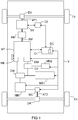
- a vehicle V comprising a transmission chain comprising, for example, a powertrain (or GMP), here of the hybrid type, a first computer C1 suitable for supervising (or managing) the operation of the GMP, an EM clutch, a BV gearbox, a second computer C2 dedicated to the BV gearbox, a coupling / decoupling means MC for the motor engine MM of the GMP, and a DC control device according to the invention.
- a powertrain or GMP
- GMP powertrain
- the GMP (here hybrid type) includes in particular a heat engine MT, a motor shaft AM, an electric machine ME, at least one motive machine MM (here an electric motor), first means of energy storage (here electric) MS1, second electrical energy storage means MS2 to which an electrical power supply network (not shown) is coupled.
- the motor machine MM is coupled to the first energy storage means MS1 which are, for example, of the low voltage type (for example around 220 V). As illustrated, this coupling can be done via an ON / DC type DC inverter.
- the transmission chain also includes a starter DM and, here, first AT1 and second AT2 transmission shafts, by way of nonlimiting example.
- the first transmission shaft AT1 is responsible for rotating the wheels of the front axle TV of the vehicle V (preferably via a front differential DV), while the second transmission shaft AT2 is responsible for driving the rotation the rear axle wheels TR of vehicle V (preferably via a rear differential DR).
- the reverse is also possible.
- the heat engine MT comprises a crankshaft (not shown) which is fixedly secured to an AM engine shaft in order to drive the latter (AM) in rotation.
- the gearbox BV comprises at least one input shaft (or primary) intended to receive the torque produced by the heat engine MT via the clutch EM, and an output shaft intended to receive this torque via the drive shaft input in order to communicate it to the first transmission shaft AT1 to which it is coupled and which is indirectly coupled to the front wheels (here) of the vehicle V via the front differential DV.
- the clutch EM comprises a flywheel fixedly attached to the engine shaft AM and a clutch disc fixedly attached to the input shaft of the gearbox BV.
- the gearbox BV can be an automatic gearbox (or BVA) or a piloted manual gearbox (BVMP or DCT (dual clutch transmission)), since it receives its commands from the second computer C2 dedicated to it and which does not decide directly from the report that must engage but receives report instructions to initiate the re c part of the first computer C1 which supervises the operation of the GMP.
- BVA automatic gearbox
- BVMP piloted manual gearbox
- DCT dual clutch transmission
- the ME electric machine is coupled to the MT heat engine, for example via a front strap. It is, for example, an alternator-starter responsible for launching the thermal engine MT in order to allow it to start, including in the presence of a stop control system and automatic restart (or “stop and start ”), and to produce a torque intended to be transmitted to the first transmission shaft AT1 via the clutch EM and the gearbox BV.
- This torque production is done thanks to the energy which is stored in the first storage means MS1, as well as thanks to the energy which is supplied directly by the motor machine MM, if the latter is controlled in generator mode, and without requesting the energy present in the first storage means MS1 (this is called power derivation).
- the coupling / decoupling means MC is here responsible for coupling / decoupling the motor machine MM to / from the second transmission shaft AT2, on the order of the first computer C1, in order to communicate the torque that it produces, thanks to the stored energy. in the first storage means MS1, to the second transmission shaft AT2 which is indirectly coupled to the rear wheels (here) of the vehicle V via the rear differential DR.
- This coupling / decoupling means MC is for example a dog clutch mechanism or else a clutch or a hydraulic torque converter.
- the starter DM is responsible for starting the thermal engine MT when the driver makes an activation request by means of a start key or button (or “push”).
- This DM starter is coupled to the second storage means MS2, preferably via a CV converter of the DC / DC type.
- the latter can also be coupled, as shown without limitation, to the inverter ON and to the first electrical energy storage means MS1.
- the second storage means MS2 are arranged in the form of a very low voltage type battery (for example 12 V, 24 V or 48 V).
- the electrical supply network (or on-board network) is responsible for supplying electrical energy to the electrical and electronic equipment of vehicle V. It is connected to the second storage means MS2.
- the operations of the heat engine MT, of the motive machine MM, of the coupling / decoupling means MC, of the electric machine ME and of the starter DM can be controlled by the first computer C1.
- the latter (C1) is particularly responsible for frequently determining a torque DC set point, which defines the torque must produce GMP, and a ratio setpoint to engage c re, which defines the next report that BV gearbox will have engage and which is a function of the torque setpoint cc and intended for the second computer C2.
- Each torque setpoint cc is determined by the first computer C1 as a function of first i1 and second i2 information which is supplied by the second computer C2 (dedicated to the gearbox BV).
- Each first item of information i1 is representative of the ratio which is actually engaged in the gearbox BV at the instant t considered.
- Every second information I2 is representative of a target ratio which is defined by the latest ratio setpoint to initiate re c which has been supplied by the first computer C1. It (i2) therefore represents the next gear to be engaged in the BV gearbox.
- the second computer C2 is responsible for generating commands to engage in the gearbox the gearbox ratio which is defined by the latest ratio setpoint to initiate re c provided by the first computer C1. It is also responsible for frequently supplying the first computer C1 with first i1 and second i2 information.
- the invention proposes in particular to implement, within vehicle V, a method intended to control the torque which is produced by the GMP of this vehicle V, when the first computer C1 does not have the first i1 and second i2 information.
- This implementation can be done by means of a DC control device which can, as illustrated without limitation on the figure 1 , to be installed in the first C1 computer. But this is not compulsory. Indeed, it could be external to the first computer C1, while being coupled to the latter (C1). In the latter case, it can itself be arranged in the form of a dedicated computer comprising a possible dedicated program, for example. Consequently, a DC control device according to the invention can be produced in the form of software modules (or computer modules (or “software”)), or else electronic circuits (or “hardware”), or else '' a combination of electronic circuits and software modules.
- the (control) method according to the invention comprises a step which is triggered each time the first computer C1 does not have the first i1 and second i2 information which should normally be supplied to it by the second computer C2. This situation results from a communication failure between the first C1 and second C2 computers, which comes either from the fact that the second computer C2 does not send the first i1 and second i2 information, or from the fact that the first computer C1 does not can no longer receive or read the first i1 and second i2 information.
- the first computer C1 determines at a time t the torque setpoint cc as a function of two setpoints of report to engage c re (t- ⁇ t1) and c re (t- ⁇ t2), previously supplied respectively to the first t- ⁇ t1 and second t- ⁇ t2 chosen previous moments, replacing respectively the first i1 and second i2 information.
- the DC (control) device will use the report setpoint to engage c re (t- ⁇ t1) that it had supplied ⁇ t1 milliseconds earlier to the second computer C2 in place of the first information i1 of which it does not have, and the report setpoint to be engaged c re (t- ⁇ t2) which it had supplied ⁇ t2 milliseconds earlier to the second computer C2 in place of the second information i2 which it does not have, to determine the new torque setpoint cc.
- the first computer C1 (and more precisely its DC device) in a way simulates an operation of the GMP in nominal situation, which amounts to carrying out a piloting of the reports in "open loop". He can therefore continue to develop torque settings that meet the driver's wishes and thus allow the GMP to significantly maintain its nominal performance. Thus, the driver has all the performance of vehicle V despite the failure.
- the device DC stored in storage means a history report instructions to initiate re c he provided to the second computer C2, corresponding times when he respectively provided.
- the storage means can store ten or twenty final instructions to report to initiate re c provided (note that these values are calibrated and are therefore only examples).
- These storage means can be part of the DC device or else of the first computer C1.
- these storage means can, for example, be produced in the form of a memory, possibly of the software type.
- first t- ⁇ t1 and second t- ⁇ t2 previous instants can advantageously result from the fact that in nominal operation, when the ratio setpoint to be engaged c re evolves, its taking into account by the second computer C2 translates all of first by switching from the target gear to the new value of the gear setpoint to be engaged.
- This first step lasts approximately ⁇ t1 milliseconds and can vary from one vehicle model to another model.
- the second computer C2 controls the various actuators of the BV gearbox to mechanically move the ratio defined by the new ratio setpoint to initiate re c, then gives the second information i2 its new value.
- This second step lasts approximately ⁇ t2 milliseconds and can vary from one vehicle model to another model.
- the first prior chosen instant t-.DELTA.t1 may depend on the time required for the second computer C2 to take into account a new report setpoint to engage c re provided by the first computer C1 and replace a target ratio value in course by this new gear setpoint to be engaged c re .
- the second previous instant chosen t- ⁇ t2 can be a function of the time required for the second computer C2 to drive the actuators of the gearbox. BV to mechanically move the ratio defined by the new ratio setpoint to initiate re c, then a new value to the second information i2.
- the first anterior instant chosen ⁇ t1 may be between approximately -150 ms relative to the instant t current and approximately -30 ms relative to the instant t current (it will be noted that these values are calibratable and therefore are not only examples). In this case, we can, for example, choose it equal to -50 ms with respect to the current time t.
- the second prior instant chosen t- ⁇ t2 can be between approximately -1200 ms relative to an instant t current and approximately -400 ms relative to an instant t current (it will be noted that these values are calibratable and are not so only examples). In this case, we can, for example, choose it equal to -500 ms relative to the current time t.
- the first computer C1 (and more precisely its DC device) can advantageously inform the driver of vehicle V of a fault which has occurred in the latter (V), so that he goes to a service after-sales service to have your vehicle V checked.
- the first computer C1 (and more precisely its DC device) can inform the driver by means of a text message or a thumbnail displayed on a screen of the vehicle V and / or a broadcast audio message. by at least one speaker from vehicle V.
- the screen may be, for example, that of the instrument panel of vehicle V, or that of the central instrument panel which is installed in or on the dashboard of vehicle V, or it may be a part of the windshield of vehicle V which is used by a head-up display device.
- the text message or the audible message may, for example, be "possible problem of torque management, please have your vehicle serviced” or "problem detected, please have your vehicle serviced”.
- the thumbnail can, for example, be the one intended for the "service” indicator.
- the first computer C1 (and more precisely its DC device) detects that it does not have the first i1 and second i2 information.
- the first computer C1 recovers at the instant t in the aforementioned storage means the two set points of report to be engaged c re (t- ⁇ t1) and c re (t - ⁇ t2) that it previously supplied to the first t- ⁇ t1 and second t- ⁇ t2 previous moments.
- the first computer C1 (and more precisely its DC device) replaces the first information i1 by the report setpoint to be engaged c re (t- ⁇ t1) recovered and the second information i2 by the report setpoint to engage c re (t- ⁇ t2) recovered.
- the first computer C1 determines a new torque setpoint cc as a function of these two ratio setpoints to be engaged c re (t- ⁇ t1) and c re (t - ⁇ t2).
- the invention makes it possible to guarantee the safety of the passengers of the vehicle because the latter remains usable, possibly in a slightly degraded manner, even when there is a communication failure.
Landscapes
- Engineering & Computer Science (AREA)
- Mechanical Engineering (AREA)
- Chemical & Material Sciences (AREA)
- Combustion & Propulsion (AREA)
- Transportation (AREA)
- Automation & Control Theory (AREA)
- General Engineering & Computer Science (AREA)
- Human Computer Interaction (AREA)
- Health & Medical Sciences (AREA)
- Biomedical Technology (AREA)
- General Health & Medical Sciences (AREA)
- Control Of Transmission Device (AREA)
Claims (10)
- Verfahren zur Steuerung des Drehmoments, das von einem Antriebsstrang eines Fahrzeugs (V) erzeugt wird, wobei das Drehmoment von einem Drehmomentsollwert abhängt, der von einem ersten Rechner (C1) bestimmt wird, der das Funktionieren des Antriebsstrangs überwacht, und wobei der Antriebsstrang mit einem Schaltgetriebe (BV) gekoppelt ist, dessen Gänge gesteuert werden, in Abhängigkeit von einem Sollwert eines Gangs, der einzulegen ist, der von dem ersten Rechner (C1) geliefert wird, durch einen zweiten Rechner (C2), der diesem Letzteren (C1) eine erste Information liefert, die für den tatsächlich eingelegten Gang repräsentativ ist, und eine zweite Information, die für einen Zielgang repräsentativ ist, die für das Bestimmen des Drehmomentsollwerts nützlich sind, dadurch gekennzeichnet, dass es einen Schritt umfasst, bei dem bei Abwesenheit der ersten und der zweiten Information der erste Rechner (C1) den Drehmomentsollwert in Abhängigkeit von zwei Sollwerten von Gängen, die einzulegen sind, die zuvor in einem ersten und einem zweiten vorhergehenden Augenblick geliefert wurden, die als Ersatz jeweils der ersten und der zweiten Information ausgewählt werden, bestimmt.
- Verfahren nach Anspruch 1, dadurch gekennzeichnet, dass der ausgewählte erste vorhergehende Augenblick von einer Dauer abhängt, die für den zweiten Rechner (C2) erforderlich ist, um einen neuen Sollwert des Gangs, der einzulegen ist, der von dem ersten Rechner (C1) geliefert wird, zu berücksichtigen, und einen aktuellen Zielgangwert durch diesen neuen Sollwert eines Gangs, der einzulegen ist, zu ersetzen, und dass der ausgewählte zweite vorhergehende Augenblick von einer Dauer abhängt, die für den zweiten Rechner (C2) erforderlich ist, um Aktuatoren des Schaltgetriebes (BV) zu steuern, um den Gang, der von dem neuen Sollwert eines Gangs, der einzulegen ist, bestimmt wird, mechanisch einzurücken, dann der zweiten Information einen neuen Wert zu geben.
- Verfahren nach einem der Ansprüche 1 und 2, dadurch gekennzeichnet, dass der ausgewählte erste vorhergehende Augenblick zwischen etwa -150 ms in Bezug auf einen aktuellen Augenblick t und etwa -30 ms in Bezug auf einen aktuellen Augenblick t ausgewählt wird.
- Verfahren nach einem der Ansprüche 1 bis 3, dadurch gekennzeichnet, dass der ausgewählte zweite vorhergehende Augenblick zwischen etwa -1200 ms in Bezug auf einen aktuellen Augenblick t und etwa -400 ms in Bezug auf einen aktuellen Augenblick t liegt.
- Verfahren nach einem der Ansprüche 1 bis 4, dadurch gekennzeichnet, dass ein Fahrer des Fahrzeugs (V) bei dem Schritt über einen Fehler informiert wird.
- Verfahren nach Anspruch 5, dadurch gekennzeichnet, dass der Fahrer mittels einer Textmeldung oder eines Bilds, die/das auf einem Bildschirm des Fahrzeugs (V) angegeben wird, und/oder einer akustischen Mitteilung, die von mindestens einem Lautsprecher des Fahrzeugs (V) ausgegeben wird, informiert wird.
- Steuervorrichtung (DC) für einen ersten Rechner (C1), der das Funktionieren eines Fahrzeugantriebsstrangs (V) überwacht, die geeignet ist, ein Drehmoment in Abhängigkeit von einem bestimmten Drehmomentsollwert zu erzeugen, und die mit einem Schaltgetriebe (BV) gekoppelt ist, dessen Gänge gesteuert werden, in Abhängigkeit von einem Sollwert eines Gangs, der einzulegen ist, der von dem ersten Rechner (C1) gesteuert wird durch einen zweiten Rechner (C2), der diesem Letzteren (C1) eine erste Information geliefert, die für den Gang, der effektiv eingelegt ist, repräsentativ ist, und eine zweite Information, die für einen Zielgang repräsentativ ist, die für das Bestimmen des Drehmomentsollwerts nützlich sind, dadurch gekennzeichnet, dass sie eingerichtet ist, um bei Abwesenheit der ersten und der zweiten Information den Drehmomentsollwert in Abhängigkeit von zwei Sollwerten eines Gangs der einzulegen ist, die zuvor in einem ersten und zweiten ausgewählten vorhergehenden Augenblick geliefert wurden, jeweils als Ersatz der ersten und der zweiten Information zu bestimmen.
- Rechner (C1) zum Überwachen des Funktionierens eines Antriebsstrangs eines Fahrzeugs (V), der geeignet ist, um ein Drehmoment in Abhängigkeit von einem bestimmten Drehmomentsollwert zu erzeugen, und mit einem Schaltgetriebe (BV) gekoppelt ist, dessen Gänge gesteuert sind, in Abhängigkeit von einem Sollwert eines Gangs, der einzulegen ist, durch einen zweiten Rechner (C2), der eine erste Information liefert, die für den effektiv eingelegten Gang repräsentativ ist, und eine zweite Information, die für einen Zielgang repräsentativ ist, die für das Bestimmen des Drehmomentsollwerts nützlich sind, dadurch gekennzeichnet, dass es eine Steuervorrichtung (DC) nach Anspruch 7 umfasst.
- Fahrzeug (V), das einen Antriebsstrang umfasst, der geeignet ist, um in Abhängigkeit von einem bestimmten Drehmomentsollwert ein Drehmoment zu erzeugen, und der mit einem Schaltgetriebe (BV) gekoppelt ist, dessen Gänge gesteuert sind, in Abhängigkeit von einem Sollwert eines Gangs, der einzulegen ist, durch einen Rechner (C2), der eine erste Information liefert, die für den tatsächlich eingelegten Gang repräsentativ ist, und eine zweite Information eines Zielgangs, liefert, die für das Bestimmen des Drehmomentsollwerts nützlich sind, dadurch gekennzeichnet, dass es außerdem einen Rechner (C1) nach Anspruch 8 umfasst, der geeignet ist, den Drehmomentsollwert zu bestimmen.
- Fahrzeug nach Anspruch 9, dadurch gekennzeichnet, dass es vom Typ Kraftfahrzeug ist.
Applications Claiming Priority (2)
| Application Number | Priority Date | Filing Date | Title |
|---|---|---|---|
| FR1554064A FR3035947B1 (fr) | 2015-05-06 | 2015-05-06 | Procede et dispositif de controle du couple d’un gmp de vehicule en cas d’indisponibilite d’informations du calculateur dedie a la boite de vitesses |
| PCT/FR2016/050837 WO2016177946A1 (fr) | 2015-05-06 | 2016-04-12 | Procédé et dispositif de contrôle du couple d'un gmp de véhicule en cas d'indisponibilité d'informations du calculateur dédié à la boîte de vitesses |
Publications (2)
| Publication Number | Publication Date |
|---|---|
| EP3292323A1 EP3292323A1 (de) | 2018-03-14 |
| EP3292323B1 true EP3292323B1 (de) | 2020-03-18 |
Family
ID=53496829
Family Applications (1)
| Application Number | Title | Priority Date | Filing Date |
|---|---|---|---|
| EP16721193.7A Active EP3292323B1 (de) | 2015-05-06 | 2016-04-12 | Verfahren und vorrichtung zur steuerung des drehmoments eines fahrzeuggetriebes bei unverfügbarkeit von informationen aus dem getriebecomputer |
Country Status (4)
| Country | Link |
|---|---|
| EP (1) | EP3292323B1 (de) |
| CN (1) | CN107580563B (de) |
| FR (1) | FR3035947B1 (de) |
| WO (1) | WO2016177946A1 (de) |
Cited By (1)
| Publication number | Priority date | Publication date | Assignee | Title |
|---|---|---|---|---|
| FR3156105A1 (fr) * | 2023-12-01 | 2025-06-06 | Stellantis Auto Sas | Contrôle du fonctionnement du gmp hybride d’un véhicule terrestre en présence d’un problème de communication interne |
Families Citing this family (2)
| Publication number | Priority date | Publication date | Assignee | Title |
|---|---|---|---|---|
| FR3061692B1 (fr) * | 2017-01-06 | 2019-05-24 | Peugeot Citroen Automobiles Sa | Procede et dispositif de controle des couples d'un gmp de vehicule en cas d'indisponibilite de l’etat de couplage d'une machine motrice |
| FR3100509B1 (fr) * | 2019-09-09 | 2023-11-24 | Psa Automobiles Sa | Contrôle du seuil de couple de démarrage thermique d’un groupe motopropulseur hybride d’un véhicule sur un trajet |
Family Cites Families (7)
| Publication number | Priority date | Publication date | Assignee | Title |
|---|---|---|---|---|
| JPH0242268A (ja) * | 1988-08-01 | 1990-02-13 | Nissan Motor Co Ltd | パワートレーンの総合制御装置 |
| CN101982360A (zh) * | 2010-11-08 | 2011-03-02 | 苏州海格新能源汽车电控系统科技有限公司 | 一种混合动力系统汽车的动态转矩协调方法 |
| EP2689980B1 (de) * | 2011-03-25 | 2019-04-24 | Aisin Seiki Kabushiki Kaisha | Getriebesteuerungsvorrichtung für ein hybridfahrzeug |
| JP5733022B2 (ja) * | 2011-05-24 | 2015-06-10 | スズキ株式会社 | ツインクラッチ式自動変速機の制御装置 |
| EP2594445B1 (de) * | 2011-11-16 | 2017-03-08 | Aisin Ai Co., Ltd. | Getriebeschaltung-steuerungsvorrichtung für ein hybridfahrzeug-antriebssystem |
| US8942876B2 (en) * | 2013-02-13 | 2015-01-27 | Ford Global Technologies, Llc | Method and system for controlling a user requested shift in a hybrid vehicle |
| CN104029675B (zh) * | 2013-03-04 | 2017-07-11 | 上海汽车集团股份有限公司 | 混合动力汽车及其动力系统转矩控制方法 |
-
2015
- 2015-05-06 FR FR1554064A patent/FR3035947B1/fr not_active Expired - Fee Related
-
2016
- 2016-04-12 WO PCT/FR2016/050837 patent/WO2016177946A1/fr not_active Ceased
- 2016-04-12 CN CN201680026035.XA patent/CN107580563B/zh not_active Expired - Fee Related
- 2016-04-12 EP EP16721193.7A patent/EP3292323B1/de active Active
Non-Patent Citations (1)
| Title |
|---|
| None * |
Cited By (1)
| Publication number | Priority date | Publication date | Assignee | Title |
|---|---|---|---|---|
| FR3156105A1 (fr) * | 2023-12-01 | 2025-06-06 | Stellantis Auto Sas | Contrôle du fonctionnement du gmp hybride d’un véhicule terrestre en présence d’un problème de communication interne |
Also Published As
| Publication number | Publication date |
|---|---|
| FR3035947B1 (fr) | 2018-10-26 |
| CN107580563B (zh) | 2020-08-04 |
| WO2016177946A1 (fr) | 2016-11-10 |
| CN107580563A (zh) | 2018-01-12 |
| FR3035947A1 (fr) | 2016-11-11 |
| EP3292323A1 (de) | 2018-03-14 |
Similar Documents
| Publication | Publication Date | Title |
|---|---|---|
| EP3292323B1 (de) | Verfahren und vorrichtung zur steuerung des drehmoments eines fahrzeuggetriebes bei unverfügbarkeit von informationen aus dem getriebecomputer | |
| EP2861892B1 (de) | Verfahren und vorrichtung zur steuerung des eingelegten gangs eines automatikgetriebes eines fahrzeuges gemäss einer durch ein geschwindigkeitssteuerungssystem angeforderten beschleunigung | |
| EP3074257B1 (de) | Verfahren und system zum starten eines verbrennungsmotors | |
| EP3589510B1 (de) | Vorrichtung zur steuerung von kopplungen/entkopplungen einer antriebsmaschine eines fahrzeugs während einer änderung des übersetzungsverhältnisses | |
| EP2850342B1 (de) | Verfahren und vorrichtung zur steuerung eines drehzahlvorwahlmechanismus eines fahrzeuggetriebes zur begrenzung der verstärkung unerwünschter frequenzen | |
| FR3061692A1 (fr) | Procede et dispositif de controle des couples d'un gmp de vehicule en cas d'indisponibilite de l’etat de couplage d'une machine motrice | |
| FR3070347B1 (fr) | Controle d’instants de declenchement d’une marche rampante par des moteur thermique et machine motrice non-thermique d’un vehicule hybride | |
| FR2996510A1 (fr) | Procede et dispositif d’aide aux decisions de couplage/ decouplage d'une machine d'un vehicule hybride, en fonction du couple offert par le moteur thermique | |
| FR3104104A1 (fr) | Véhicule à gmp à contrôle de couplage anticipé, et procédé de contrôle associé | |
| EP2608994B1 (de) | Vorrichtung zur überwachung des betriebs eines fahrzeugs | |
| FR2992041A1 (fr) | Procede et dispositif de controle de l'utilisation des moteurs electrique et thermique d'un vehicule hybride, en fonction d'une acceleration demandee par un systeme de controle de vitesse | |
| EP3917795B1 (de) | Verfahren und vorrichtung zur unterstützung eines fahrers eines parallelen hybridfahrzeugs mit einem handschaltgetriebe durch vorschlagen einer optimalen position, sowie fahrzeug | |
| WO2014057184A1 (fr) | Procédé et dispositif de contrôle de l'accélération à imposer à un véhicule en cas de réactivation d'une fonction de régulation de vitesse | |
| EP3678910B1 (de) | Verfahren zur bereitstellung eines zusätzlichen, nicht-verbrennungsmotorischen drehmoments in einem hybridfahrzeug in abhängigkeit vom beschleunigungspotential | |
| FR3017849A1 (fr) | Procede et dispositif de controle de la recuperation de l'energie acquise par une machine d'un vehicule hybride, apres un decouplage de la chaine de transmission | |
| WO2026074237A1 (fr) | Surveillance du couple moteur fourni aux roues motrices d'un véhicule terrestre à groupe motopropulseur hybride | |
| FR3070344A1 (fr) | Dispositif et procede de controle de l’intensite de deceleration d’un vehicule hybride induite par une machine non-thermique | |
| FR2998850A1 (fr) | Procede et dispositif de fourniture d'informations relatives a une phase d'apprentissage ou de diagnostic devant etre effectuee dans un vehicule | |
| FR3001259A1 (fr) | Dispositif de controle du couple d'un moteur thermique lors d'un changement de rapport dans une boite de vitesses robotisee | |
| WO2013117844A1 (fr) | Procede et systeme de gestion semi-automatisee d'une traction hybride | |
| WO2019092336A1 (fr) | Procede de controle du demarrage d'un moteur thermique pour un vehicule automobile | |
| FR3034736A1 (fr) | Procede et dispositif de securisation de la reactivation d'un groupe motopropulseur hybride d'un vehicule en cas d'echec du redemarrage du moteur thermique | |
| FR3034485A1 (fr) | Procede et dispositif de prediction de changement de rapport d'une boite de vitesses de vehicule a rapports selectionnables par le conducteur | |
| EP3198135A1 (de) | Verfahren und vorrichtung zur steuerung der reaktivierung eines fahrzeugantriebsstrangs gemäss der geschwindigkeit des fahrzeugs | |
| FR2956440A1 (fr) | Procede de controle commande d'un groupe motopropulseur d'un vehicule automobile |
Legal Events
| Date | Code | Title | Description |
|---|---|---|---|
| STAA | Information on the status of an ep patent application or granted ep patent |
Free format text: STATUS: THE INTERNATIONAL PUBLICATION HAS BEEN MADE |
|
| PUAI | Public reference made under article 153(3) epc to a published international application that has entered the european phase |
Free format text: ORIGINAL CODE: 0009012 |
|
| STAA | Information on the status of an ep patent application or granted ep patent |
Free format text: STATUS: REQUEST FOR EXAMINATION WAS MADE |
|
| 17P | Request for examination filed |
Effective date: 20171107 |
|
| AK | Designated contracting states |
Kind code of ref document: A1 Designated state(s): AL AT BE BG CH CY CZ DE DK EE ES FI FR GB GR HR HU IE IS IT LI LT LU LV MC MK MT NL NO PL PT RO RS SE SI SK SM TR |
|
| AX | Request for extension of the european patent |
Extension state: BA ME |
|
| DAV | Request for validation of the european patent (deleted) | ||
| DAX | Request for extension of the european patent (deleted) | ||
| RIC1 | Information provided on ipc code assigned before grant |
Ipc: B60W 50/14 20120101ALI20190903BHEP Ipc: B60W 10/06 20060101ALI20190903BHEP Ipc: B60W 20/50 20160101ALI20190903BHEP Ipc: B60W 10/11 20120101ALI20190903BHEP Ipc: B60W 50/029 20120101ALI20190903BHEP Ipc: B60K 6/52 20071001ALI20190903BHEP Ipc: B60K 6/547 20071001ALI20190903BHEP Ipc: B60W 10/08 20060101ALI20190903BHEP Ipc: F16H 61/12 20100101AFI20190903BHEP |
|
| GRAP | Despatch of communication of intention to grant a patent |
Free format text: ORIGINAL CODE: EPIDOSNIGR1 |
|
| STAA | Information on the status of an ep patent application or granted ep patent |
Free format text: STATUS: GRANT OF PATENT IS INTENDED |
|
| INTG | Intention to grant announced |
Effective date: 20191016 |
|
| GRAS | Grant fee paid |
Free format text: ORIGINAL CODE: EPIDOSNIGR3 |
|
| GRAA | (expected) grant |
Free format text: ORIGINAL CODE: 0009210 |
|
| STAA | Information on the status of an ep patent application or granted ep patent |
Free format text: STATUS: THE PATENT HAS BEEN GRANTED |
|
| AK | Designated contracting states |
Kind code of ref document: B1 Designated state(s): AL AT BE BG CH CY CZ DE DK EE ES FI FR GB GR HR HU IE IS IT LI LT LU LV MC MK MT NL NO PL PT RO RS SE SI SK SM TR |
|
| REG | Reference to a national code |
Ref country code: GB Ref legal event code: FG4D Free format text: NOT ENGLISH Ref country code: DE Ref legal event code: R084 Ref document number: 602016031995 Country of ref document: DE |
|
| REG | Reference to a national code |
Ref country code: DE Ref legal event code: R096 Ref document number: 602016031995 Country of ref document: DE |
|
| REG | Reference to a national code |
Ref country code: AT Ref legal event code: REF Ref document number: 1246258 Country of ref document: AT Kind code of ref document: T Effective date: 20200415 Ref country code: IE Ref legal event code: FG4D Free format text: LANGUAGE OF EP DOCUMENT: FRENCH |
|
| REG | Reference to a national code |
Ref country code: GB Ref legal event code: 746 Effective date: 20200505 |
|
| PG25 | Lapsed in a contracting state [announced via postgrant information from national office to epo] |
Ref country code: FI Free format text: LAPSE BECAUSE OF FAILURE TO SUBMIT A TRANSLATION OF THE DESCRIPTION OR TO PAY THE FEE WITHIN THE PRESCRIBED TIME-LIMIT Effective date: 20200318 Ref country code: RS Free format text: LAPSE BECAUSE OF FAILURE TO SUBMIT A TRANSLATION OF THE DESCRIPTION OR TO PAY THE FEE WITHIN THE PRESCRIBED TIME-LIMIT Effective date: 20200318 Ref country code: NO Free format text: LAPSE BECAUSE OF FAILURE TO SUBMIT A TRANSLATION OF THE DESCRIPTION OR TO PAY THE FEE WITHIN THE PRESCRIBED TIME-LIMIT Effective date: 20200618 |
|
| REG | Reference to a national code |
Ref country code: NL Ref legal event code: MP Effective date: 20200318 |
|
| PG25 | Lapsed in a contracting state [announced via postgrant information from national office to epo] |
Ref country code: HR Free format text: LAPSE BECAUSE OF FAILURE TO SUBMIT A TRANSLATION OF THE DESCRIPTION OR TO PAY THE FEE WITHIN THE PRESCRIBED TIME-LIMIT Effective date: 20200318 Ref country code: BG Free format text: LAPSE BECAUSE OF FAILURE TO SUBMIT A TRANSLATION OF THE DESCRIPTION OR TO PAY THE FEE WITHIN THE PRESCRIBED TIME-LIMIT Effective date: 20200618 Ref country code: GR Free format text: LAPSE BECAUSE OF FAILURE TO SUBMIT A TRANSLATION OF THE DESCRIPTION OR TO PAY THE FEE WITHIN THE PRESCRIBED TIME-LIMIT Effective date: 20200619 Ref country code: LV Free format text: LAPSE BECAUSE OF FAILURE TO SUBMIT A TRANSLATION OF THE DESCRIPTION OR TO PAY THE FEE WITHIN THE PRESCRIBED TIME-LIMIT Effective date: 20200318 Ref country code: SE Free format text: LAPSE BECAUSE OF FAILURE TO SUBMIT A TRANSLATION OF THE DESCRIPTION OR TO PAY THE FEE WITHIN THE PRESCRIBED TIME-LIMIT Effective date: 20200318 |
|
| REG | Reference to a national code |
Ref country code: LT Ref legal event code: MG4D |
|
| PG25 | Lapsed in a contracting state [announced via postgrant information from national office to epo] |
Ref country code: NL Free format text: LAPSE BECAUSE OF FAILURE TO SUBMIT A TRANSLATION OF THE DESCRIPTION OR TO PAY THE FEE WITHIN THE PRESCRIBED TIME-LIMIT Effective date: 20200318 |
|
| PG25 | Lapsed in a contracting state [announced via postgrant information from national office to epo] |
Ref country code: CZ Free format text: LAPSE BECAUSE OF FAILURE TO SUBMIT A TRANSLATION OF THE DESCRIPTION OR TO PAY THE FEE WITHIN THE PRESCRIBED TIME-LIMIT Effective date: 20200318 Ref country code: RO Free format text: LAPSE BECAUSE OF FAILURE TO SUBMIT A TRANSLATION OF THE DESCRIPTION OR TO PAY THE FEE WITHIN THE PRESCRIBED TIME-LIMIT Effective date: 20200318 Ref country code: SK Free format text: LAPSE BECAUSE OF FAILURE TO SUBMIT A TRANSLATION OF THE DESCRIPTION OR TO PAY THE FEE WITHIN THE PRESCRIBED TIME-LIMIT Effective date: 20200318 Ref country code: IS Free format text: LAPSE BECAUSE OF FAILURE TO SUBMIT A TRANSLATION OF THE DESCRIPTION OR TO PAY THE FEE WITHIN THE PRESCRIBED TIME-LIMIT Effective date: 20200718 Ref country code: SM Free format text: LAPSE BECAUSE OF FAILURE TO SUBMIT A TRANSLATION OF THE DESCRIPTION OR TO PAY THE FEE WITHIN THE PRESCRIBED TIME-LIMIT Effective date: 20200318 Ref country code: LT Free format text: LAPSE BECAUSE OF FAILURE TO SUBMIT A TRANSLATION OF THE DESCRIPTION OR TO PAY THE FEE WITHIN THE PRESCRIBED TIME-LIMIT Effective date: 20200318 Ref country code: EE Free format text: LAPSE BECAUSE OF FAILURE TO SUBMIT A TRANSLATION OF THE DESCRIPTION OR TO PAY THE FEE WITHIN THE PRESCRIBED TIME-LIMIT Effective date: 20200318 Ref country code: PT Free format text: LAPSE BECAUSE OF FAILURE TO SUBMIT A TRANSLATION OF THE DESCRIPTION OR TO PAY THE FEE WITHIN THE PRESCRIBED TIME-LIMIT Effective date: 20200812 |
|
| RAP2 | Party data changed (patent owner data changed or rights of a patent transferred) |
Owner name: PSA AUTOMOBILES SA |
|
| REG | Reference to a national code |
Ref country code: AT Ref legal event code: MK05 Ref document number: 1246258 Country of ref document: AT Kind code of ref document: T Effective date: 20200318 |
|
| REG | Reference to a national code |
Ref country code: CH Ref legal event code: PL |
|
| REG | Reference to a national code |
Ref country code: DE Ref legal event code: R097 Ref document number: 602016031995 Country of ref document: DE |
|
| PG25 | Lapsed in a contracting state [announced via postgrant information from national office to epo] |
Ref country code: MC Free format text: LAPSE BECAUSE OF FAILURE TO SUBMIT A TRANSLATION OF THE DESCRIPTION OR TO PAY THE FEE WITHIN THE PRESCRIBED TIME-LIMIT Effective date: 20200318 |
|
| PLBE | No opposition filed within time limit |
Free format text: ORIGINAL CODE: 0009261 |
|
| STAA | Information on the status of an ep patent application or granted ep patent |
Free format text: STATUS: NO OPPOSITION FILED WITHIN TIME LIMIT |
|
| PG25 | Lapsed in a contracting state [announced via postgrant information from national office to epo] |
Ref country code: DK Free format text: LAPSE BECAUSE OF FAILURE TO SUBMIT A TRANSLATION OF THE DESCRIPTION OR TO PAY THE FEE WITHIN THE PRESCRIBED TIME-LIMIT Effective date: 20200318 Ref country code: LU Free format text: LAPSE BECAUSE OF NON-PAYMENT OF DUE FEES Effective date: 20200412 Ref country code: CH Free format text: LAPSE BECAUSE OF NON-PAYMENT OF DUE FEES Effective date: 20200430 Ref country code: IT Free format text: LAPSE BECAUSE OF FAILURE TO SUBMIT A TRANSLATION OF THE DESCRIPTION OR TO PAY THE FEE WITHIN THE PRESCRIBED TIME-LIMIT Effective date: 20200318 Ref country code: AT Free format text: LAPSE BECAUSE OF FAILURE TO SUBMIT A TRANSLATION OF THE DESCRIPTION OR TO PAY THE FEE WITHIN THE PRESCRIBED TIME-LIMIT Effective date: 20200318 Ref country code: LI Free format text: LAPSE BECAUSE OF NON-PAYMENT OF DUE FEES Effective date: 20200430 Ref country code: ES Free format text: LAPSE BECAUSE OF FAILURE TO SUBMIT A TRANSLATION OF THE DESCRIPTION OR TO PAY THE FEE WITHIN THE PRESCRIBED TIME-LIMIT Effective date: 20200318 |
|
| REG | Reference to a national code |
Ref country code: BE Ref legal event code: MM Effective date: 20200430 |
|
| 26N | No opposition filed |
Effective date: 20201221 |
|
| PG25 | Lapsed in a contracting state [announced via postgrant information from national office to epo] |
Ref country code: PL Free format text: LAPSE BECAUSE OF FAILURE TO SUBMIT A TRANSLATION OF THE DESCRIPTION OR TO PAY THE FEE WITHIN THE PRESCRIBED TIME-LIMIT Effective date: 20200318 Ref country code: BE Free format text: LAPSE BECAUSE OF NON-PAYMENT OF DUE FEES Effective date: 20200430 |
|
| PG25 | Lapsed in a contracting state [announced via postgrant information from national office to epo] |
Ref country code: IE Free format text: LAPSE BECAUSE OF NON-PAYMENT OF DUE FEES Effective date: 20200412 |
|
| PG25 | Lapsed in a contracting state [announced via postgrant information from national office to epo] |
Ref country code: SI Free format text: LAPSE BECAUSE OF FAILURE TO SUBMIT A TRANSLATION OF THE DESCRIPTION OR TO PAY THE FEE WITHIN THE PRESCRIBED TIME-LIMIT Effective date: 20200318 |
|
| PG25 | Lapsed in a contracting state [announced via postgrant information from national office to epo] |
Ref country code: TR Free format text: LAPSE BECAUSE OF FAILURE TO SUBMIT A TRANSLATION OF THE DESCRIPTION OR TO PAY THE FEE WITHIN THE PRESCRIBED TIME-LIMIT Effective date: 20200318 Ref country code: MT Free format text: LAPSE BECAUSE OF FAILURE TO SUBMIT A TRANSLATION OF THE DESCRIPTION OR TO PAY THE FEE WITHIN THE PRESCRIBED TIME-LIMIT Effective date: 20200318 Ref country code: CY Free format text: LAPSE BECAUSE OF FAILURE TO SUBMIT A TRANSLATION OF THE DESCRIPTION OR TO PAY THE FEE WITHIN THE PRESCRIBED TIME-LIMIT Effective date: 20200318 |
|
| PG25 | Lapsed in a contracting state [announced via postgrant information from national office to epo] |
Ref country code: MK Free format text: LAPSE BECAUSE OF FAILURE TO SUBMIT A TRANSLATION OF THE DESCRIPTION OR TO PAY THE FEE WITHIN THE PRESCRIBED TIME-LIMIT Effective date: 20200318 Ref country code: AL Free format text: LAPSE BECAUSE OF FAILURE TO SUBMIT A TRANSLATION OF THE DESCRIPTION OR TO PAY THE FEE WITHIN THE PRESCRIBED TIME-LIMIT Effective date: 20200318 |
|
| REG | Reference to a national code |
Ref country code: DE Ref legal event code: R081 Ref document number: 602016031995 Country of ref document: DE Owner name: STELLANTIS AUTO SAS, FR Free format text: FORMER OWNER: PSA AUTOMOBILES S.A., POISSY, FR |
|
| PGFP | Annual fee paid to national office [announced via postgrant information from national office to epo] |
Ref country code: GB Payment date: 20250319 Year of fee payment: 10 |
|
| PGFP | Annual fee paid to national office [announced via postgrant information from national office to epo] |
Ref country code: DE Payment date: 20250319 Year of fee payment: 10 |
|
| PGFP | Annual fee paid to national office [announced via postgrant information from national office to epo] |
Ref country code: FR Payment date: 20260320 Year of fee payment: 11 |