EP3292354B1 - System zur befestigung einer platte an einem träger und trägerstruktur mit dem besagten system - Google Patents
System zur befestigung einer platte an einem träger und trägerstruktur mit dem besagten system Download PDFInfo
- Publication number
- EP3292354B1 EP3292354B1 EP16726620.4A EP16726620A EP3292354B1 EP 3292354 B1 EP3292354 B1 EP 3292354B1 EP 16726620 A EP16726620 A EP 16726620A EP 3292354 B1 EP3292354 B1 EP 3292354B1
- Authority
- EP
- European Patent Office
- Prior art keywords
- panel
- supporting structure
- flange
- girder
- edge
- Prior art date
- Legal status (The legal status is an assumption and is not a legal conclusion. Google has not performed a legal analysis and makes no representation as to the accuracy of the status listed.)
- Active
Links
Images

Classifications
-
- H—ELECTRICITY
- H02—GENERATION; CONVERSION OR DISTRIBUTION OF ELECTRIC POWER
- H02S—GENERATION OF ELECTRIC POWER BY CONVERSION OF INFRARED RADIATION, VISIBLE LIGHT OR ULTRAVIOLET LIGHT, e.g. USING PHOTOVOLTAIC [PV] MODULES
- H02S30/00—Structural details of PV modules other than those related to light conversion
-
- H—ELECTRICITY
- H02—GENERATION; CONVERSION OR DISTRIBUTION OF ELECTRIC POWER
- H02S—GENERATION OF ELECTRIC POWER BY CONVERSION OF INFRARED RADIATION, VISIBLE LIGHT OR ULTRAVIOLET LIGHT, e.g. USING PHOTOVOLTAIC [PV] MODULES
- H02S20/00—Supporting structures for PV modules
- H02S20/30—Supporting structures being movable or adjustable, e.g. for angle adjustment
- H02S20/32—Supporting structures being movable or adjustable, e.g. for angle adjustment specially adapted for solar tracking
-
- F—MECHANICAL ENGINEERING; LIGHTING; HEATING; WEAPONS; BLASTING
- F16—ENGINEERING ELEMENTS AND UNITS; GENERAL MEASURES FOR PRODUCING AND MAINTAINING EFFECTIVE FUNCTIONING OF MACHINES OR INSTALLATIONS; THERMAL INSULATION IN GENERAL
- F16B—DEVICES FOR FASTENING OR SECURING CONSTRUCTIONAL ELEMENTS OR MACHINE PARTS TOGETHER, e.g. NAILS, BOLTS, CIRCLIPS, CLAMPS, CLIPS OR WEDGES; JOINTS OR JOINTING
- F16B2/00—Friction-grip releasable fastenings
- F16B2/02—Clamps, i.e. with gripping action effected by positive means other than the inherent resistance to deformation of the material of the fastening
- F16B2/06—Clamps, i.e. with gripping action effected by positive means other than the inherent resistance to deformation of the material of the fastening external, i.e. with contracting action
- F16B2/12—Clamps, i.e. with gripping action effected by positive means other than the inherent resistance to deformation of the material of the fastening external, i.e. with contracting action using sliding jaws
-
- F—MECHANICAL ENGINEERING; LIGHTING; HEATING; WEAPONS; BLASTING
- F24—HEATING; RANGES; VENTILATING
- F24S—SOLAR HEAT COLLECTORS; SOLAR HEAT SYSTEMS
- F24S25/00—Arrangement of stationary mountings or supports for solar heat collector modules
- F24S25/20—Peripheral frames for modules
-
- F—MECHANICAL ENGINEERING; LIGHTING; HEATING; WEAPONS; BLASTING
- F24—HEATING; RANGES; VENTILATING
- F24S—SOLAR HEAT COLLECTORS; SOLAR HEAT SYSTEMS
- F24S25/00—Arrangement of stationary mountings or supports for solar heat collector modules
- F24S25/30—Arrangement of stationary mountings or supports for solar heat collector modules using elongate rigid mounting elements extending substantially along the supporting surface, e.g. for covering buildings with solar heat collectors
- F24S25/33—Arrangement of stationary mountings or supports for solar heat collector modules using elongate rigid mounting elements extending substantially along the supporting surface, e.g. for covering buildings with solar heat collectors forming substantially planar assemblies, e.g. of coplanar or stacked profiles
-
- F—MECHANICAL ENGINEERING; LIGHTING; HEATING; WEAPONS; BLASTING
- F24—HEATING; RANGES; VENTILATING
- F24S—SOLAR HEAT COLLECTORS; SOLAR HEAT SYSTEMS
- F24S25/00—Arrangement of stationary mountings or supports for solar heat collector modules
- F24S25/60—Fixation means, e.g. fasteners, specially adapted for supporting solar heat collector modules
- F24S25/63—Fixation means, e.g. fasteners, specially adapted for supporting solar heat collector modules for fixing modules or their peripheral frames to supporting elements
- F24S25/634—Clamps; Clips
- F24S25/636—Clamps; Clips clamping by screw-threaded elements
-
- F—MECHANICAL ENGINEERING; LIGHTING; HEATING; WEAPONS; BLASTING
- F24—HEATING; RANGES; VENTILATING
- F24S—SOLAR HEAT COLLECTORS; SOLAR HEAT SYSTEMS
- F24S25/00—Arrangement of stationary mountings or supports for solar heat collector modules
- F24S2025/80—Special profiles
- F24S2025/801—Special profiles having hollow parts with closed cross-section
-
- Y—GENERAL TAGGING OF NEW TECHNOLOGICAL DEVELOPMENTS; GENERAL TAGGING OF CROSS-SECTIONAL TECHNOLOGIES SPANNING OVER SEVERAL SECTIONS OF THE IPC; TECHNICAL SUBJECTS COVERED BY FORMER USPC CROSS-REFERENCE ART COLLECTIONS [XRACs] AND DIGESTS
- Y02—TECHNOLOGIES OR APPLICATIONS FOR MITIGATION OR ADAPTATION AGAINST CLIMATE CHANGE
- Y02B—CLIMATE CHANGE MITIGATION TECHNOLOGIES RELATED TO BUILDINGS, e.g. HOUSING, HOUSE APPLIANCES OR RELATED END-USER APPLICATIONS
- Y02B10/00—Integration of renewable energy sources in buildings
- Y02B10/10—Photovoltaic [PV]
-
- Y—GENERAL TAGGING OF NEW TECHNOLOGICAL DEVELOPMENTS; GENERAL TAGGING OF CROSS-SECTIONAL TECHNOLOGIES SPANNING OVER SEVERAL SECTIONS OF THE IPC; TECHNICAL SUBJECTS COVERED BY FORMER USPC CROSS-REFERENCE ART COLLECTIONS [XRACs] AND DIGESTS
- Y02—TECHNOLOGIES OR APPLICATIONS FOR MITIGATION OR ADAPTATION AGAINST CLIMATE CHANGE
- Y02E—REDUCTION OF GREENHOUSE GAS [GHG] EMISSIONS, RELATED TO ENERGY GENERATION, TRANSMISSION OR DISTRIBUTION
- Y02E10/00—Energy generation through renewable energy sources
- Y02E10/40—Solar thermal energy, e.g. solar towers
- Y02E10/47—Mountings or tracking
-
- Y—GENERAL TAGGING OF NEW TECHNOLOGICAL DEVELOPMENTS; GENERAL TAGGING OF CROSS-SECTIONAL TECHNOLOGIES SPANNING OVER SEVERAL SECTIONS OF THE IPC; TECHNICAL SUBJECTS COVERED BY FORMER USPC CROSS-REFERENCE ART COLLECTIONS [XRACs] AND DIGESTS
- Y02—TECHNOLOGIES OR APPLICATIONS FOR MITIGATION OR ADAPTATION AGAINST CLIMATE CHANGE
- Y02E—REDUCTION OF GREENHOUSE GAS [GHG] EMISSIONS, RELATED TO ENERGY GENERATION, TRANSMISSION OR DISTRIBUTION
- Y02E10/00—Energy generation through renewable energy sources
- Y02E10/50—Photovoltaic [PV] energy
Definitions
- the invention relates to a system for fixing at least one solar panel to a supporting structure of a solar module of a solar tracker, as well as a supporting structure of a solar module comprising it.
- This holding system comprises a set of side members comprising a longitudinal elongated opening which gives the side members a “U” shape, in section, the top of the branches of the “U” defining a support surface on which the solar panels come to bear, during assembly. The latter are held flat against the edges of the longitudinal elongated opening using a clamping assembly.
- One aim of the invention is to provide a system for fixing a panel, such as a solar panel, to a supporting structure which is simple to implement while having optimal mechanical strength.
- the invention provides a system for fixing at least one panel, such as a solar panel, to a supporting structure comprising at least one spar extending in a first direction, the spar comprising a gripping edge and a panel support surface, the system comprising a flange, a toad and a clamping assembly connecting the flange to the toad arranged so as to sandwich, during assembly, the gripping edge of the spar and the panel resting on the support surface of the spar, the toad comprising a first series of claws extending in projection substantially parallel to an axis of the clamping assembly in the direction of the flange, the claws being intended to cooperate, by clawing, with the gripping edge of the spar, during assembly.
- a supporting structure for at least one panel such as a solar panel, comprising at least one spar, comprising a gripping edge, a support surface for the panel and extending in a first direction, and at least one fixing system having at least one of the preceding technical characteristics, the spar comprising a thin wall and having a closed section.
- a solar module is positioned on a ground and comprises, for this purpose, a base fixed to this ground.
- the base supports a mechanism for orienting the solar module.
- the solar module comprises means for processing solar radiation, such as a series of solar panels 1 which are held on a supporting structure according to the invention of the solar module using a fixing system according to the invention which we will now describe in more detail.
- the solar module is a fixed structure.
- the supporting structure according to the invention comprises at least one spar 5 extending in a first direction parallel to a longitudinal axis of the spar 5.
- the spar 5 is here a beam.
- the spar 5 is hollow and has, in section, a closed geometric shape which is generally rectangular.
- the spar 5 comprises a wall 51 formed from a sheet of thin metal material.
- the spar 5 comprises two lateral sides 55 and 56 extending at a distance opposite each other and connected to each other by an upper side 54 and a lower side 57.
- the metal material of the sheet is preferably electrically conductive, such as steel, aluminum or one of their alloys.
- the spar 5 is obtained by an extrusion process or by a profiling process using rollers ("roll-forming" according to the English terminology) of the sheet of metal material which is then stapled and/or welded 53 to itself at the longitudinal lateral edges, here in order to form the lower side 57.
- this staple or weld can form any other side of the spar.
- the spar 5 comprises a gripping edge 52 extending in projection, laterally in the extension of the upper side 54, of one 56 of the lateral sides of the spar 5.
- the gripping edge 52 is made by folding the sheet of material, allowing to have a gripping edge 52 made of the same material as the rest of the spar 5. This edge can also be the location of the closing of the profile (by a staple or by welding).
- the upper side 54 has a bearing surface 541 which extends onto the gripping edge 52.
- the supporting structure according to the invention is intended to receive at least one panel 1, such as for example a solar panel.
- the panel 1 preferably comprises a metal frame 2 which has a lower face 21 in the figures.
- the lower face 21 of the frame 2 rests on the bearing surface 541 of the spar 5, a longitudinal axis of the frame is then substantially perpendicular to the longitudinal axis of the spar 5.
- the frame 2 of the panel 5 is electrically conductive metal and therefore makes it possible to earth the solar panel.
- the supporting structure according to the invention comprises at least one fixing system 3 according to the invention.
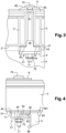
- the fixing system 3 according to the invention comprises an upper flange 6, a lower toad 4 and a clamping element 7, 72 comprising a screw 7 and a nut 72.
- the flange 6 is of a general “T” shape in section comprising a tail 61 surmounted by a cap whose edges 62 extend perpendicular to the tail 61.
- the tail 61 has a “U” shape in section.
- the base of the tail 61 of the flange 6 has at least one orifice capable of receiving the screw 7 of the clamping element.
- the screw 7 comprises, at one end, a head 73 and a thread 71 at the other end.
- the thread 71 is intended to cooperate with the nut 72.
- the toad 4 is, here, in a “U” shaped section. It comprises a substantially flat bottom 41, comprising a through orifice 45 intended to receive through the threaded part 72 of the screw 7. Laterally, the toad 4 comprises a first branch 42 extending substantially orthogonally from a lateral edge of the bottom 41. The first branch 42 comprises at a peak a first series of claws 46 oriented in the extension of the first branch 42. At another lateral edge of the bottom 41 opposite the previous lateral edge, the toad comprises a second branch 43 extending substantially orthogonally from this other lateral edge of the bottom 41, substantially parallel to the first branch 42 and opposite it. The second branch 43 comprises at a peak a second series of claws 44 oriented in the extension of the second branch 43.
- the second branch 43 further comprises at its peak a finger 45 also extending in the extension of the second branch 43.
- the finger 45 is located in the middle of the second series of claws 44 and extends above them.
- the finger 45 has a width substantially equivalent to a width of the tail 61 of the flange 6.
- the first branch 42 has a height less than a height of the second branch 43.
- the difference in height between the first 42 and second 43 branches of the toad 4 is of the order of a thickness of the gripping edge 52 of the spar 5.
- the toad 40 differs from the toad 4 previously described by the fact that the first branch 42 has, at its top, two claws 441 oriented in the extension of the first branch 42, each located at an edge adjacent to the lateral edge from which the first branch 41 extends. These two claws 441 form a first series of claws.
- the second branch 43 comprises, at its top, two claws 440 oriented in the extension of the second branch 42, each located at an edge adjacent to the lateral edge from which the second branch 43 extends and on either side of the finger 45. These two claws 440 form a second series of claws.
- the toad may be of any generally flat shape and have claws distributed over at least a portion of the edges of the generally flat shape of the toad.
- the toad may have a cup shape.
- the toad does not have claws on the edges of the shape.
- Such a toad may be used to secure panels that do not include a frame, for example.
- the toad whatever its shape, can be made by stamping, folding or molding.
- At least one solar panel 1 is positioned on the supporting structure according to the invention resting on the bearing surface 541 of at least one spar 5 of the supporting structure according to the invention.
- the solar panel 1 is positioned such that a portion of the frame 2 has its longitudinal axis substantially perpendicular to that of the spar 5 and that the lower face 21 of the frame 2 comes to bear on the bearing surface 541 of the spar 5.
- at least one fixing system 3 according to the invention is put in place.
- the flange 6 is positioned so that one of the edges 62 comes to bear against an upper face of the frame 2 of the panel 1, a lateral side of the tail 61 of the flange 6 coming to bear against an external lateral face of the frame 2 of the panel 1.
- the toad 4 or 40 is positioned so that the first series of claws 46 or 441 come to claw a bottom of the gripping edge 52 and at least a part of the second series of claws 44 or 440 come to claw the lower surface 21 of the frame 2 of the panel 1, the finger 45 coming to extend along the external lateral face of the frame 2 of the panel 1, one side of the finger being able to come to bear against this external lateral face of the frame 2 of the panel 1.
- the screw 7 is then put in place: preferably, it is threaded by the flange 6, through the orifice located on the base of the tail 61, then through the orifice 45 of the toad 4 or 40.
- the screw then extends between the flange 6 and the toad 4 or 40, along and opposite the external lateral face of the frame 2 of the panel 1.
- the nut 71 is then placed on the threaded part 71 of the screw 7 which protrudes from the toad 4 or 40.
- the below the head 73 of the screw 7 comprises at least one flat which is inserted between the branches of the “U” shape of the tail 61 of the flange 6 to keep said bolt 7 immobile in rotation about its longitudinal axis during tightening of the nut 72.
- a supporting structure according to the invention associated with a tightening system according to the invention makes it possible to facilitate assembly of the panels 1 because the final fixing is carried out from below the panels 1 (i.e. on the side of the supporting structure and the side members 5) by thus facilitating access to the tightening (nut 72) from below.
- the fixing system 3 according to the invention is arranged so as to hold the two panels 1 on the supporting structure according to the invention simultaneously and similarly to what has just been described.
- the tail 61 of the flange 6 and the finger 45 of the toad 4 or 40 have an additional role of spacing between the two panels 1 thus held on the supporting structure according to the invention.
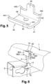
- FIG. 6 An alternative embodiment of the flange 600 is illustrated in figure 6 .
- This variant embodiment of the flange 600 makes it possible to optimally fix a single panel 1 on the spar 5, such as an end panel of a row or column of adjacent panels.
- the flange 600 has only one rim 62 extending perpendicularly to the tail 61 in the shape of a “U”.
- the vertical wall of the tail 61 at the top of which the rim 62 projects, extends downwards under the bottom of the tail 61 by a wall 601.
- the wall 601 comes to bear against a lateral edge of the panel 1 to be fixed, which prevents the flange 600 from tilting and makes it possible to secure the fixing.
- the opposite vertical wall 602 of the tail 61 does not have a rim extending perpendicular to its top which is however at the same level as the rim 62.
- the head 73 of the screw 7 comes to bear on the top of the opposite vertical wall 602 and on the rim 62.
- the underside of the head 73 of the screw 7 may comprise at least one flat which is inserted between the branches of the “U” shape of the tail 61 of the flange 600 to keep said bolt 7 immobile in rotation about its longitudinal axis when tightening the nut 72.
- the opposite vertical wall 602 extends downwards under the bottom of the tail 61 and ends with a rim 603 formed in one piece and extending perpendicularly towards the wall 601.
- the support of the head 73 of the screw 7 tends to deform the opposite vertical wall 602 in the direction of an opening of the “U” shape of the tail 61 of the flange 600. This deformation is stopped by the support of the rim 603 against the rod of the screw 7.
- the clamping element 7,72 comprises a structural rivet system.
- the use of structural rivets makes it possible to ensure better safety and holding of the clamping carried out by the element of tightening during use.
- the structural rivets due to their arrangement, can play an anti-theft role once in place.
Landscapes
- Engineering & Computer Science (AREA)
- General Engineering & Computer Science (AREA)
- Sustainable Development (AREA)
- Mechanical Engineering (AREA)
- Life Sciences & Earth Sciences (AREA)
- Physics & Mathematics (AREA)
- Sustainable Energy (AREA)
- Thermal Sciences (AREA)
- Chemical & Material Sciences (AREA)
- Combustion & Propulsion (AREA)
- Connection Of Plates (AREA)
- Roof Covering Using Slabs Or Stiff Sheets (AREA)
- Photovoltaic Devices (AREA)
- Joining Of Building Structures In Genera (AREA)
- Railway Tracks (AREA)
Claims (9)
- Befestigungssystem (3) mindestens einer Platte (1) an einer Trägerstruktur, umfassend mindestens einen Längsträger (5), der sich in eine erste Richtung erstreckt, wobei der Längsträger einen Greifrand (52) und eine Anlagefläche (541) der Platte aufweist, das System umfassend einen Flansch (6; 600), eine Klemmplatte (4; 400) und eine Klemmanordnung (7), die den Flansch mit der Klemmplatte verbindet, die angeordnet sind, um den Greifrand des Längsträgers und die Platte, die an der Anlagefläche des Längsträgers anliegt, beim Zusammenbau in Sandwichform einzuspannen, dadurch gekennzeichnet, dass die Klemmplatte eine erste Reihe von Klauen (46; 441) aufweist, die sich an einem ersten Rand (42) der Klemmplatte befinden und sich im Wesentlichen parallel zu einer Achse der Klemmanordnung in Richtung des Flanschs hervorstehend erstrecken, die Klauen dieser ersten Reihe von Klauen dazu bestimmt sind, beim Zusammenbau durch Einspannen mit dem Greifrand des Längsträgers zusammenzuwirken, und dass die Klemmplatte eine zweite Reihe von Klauen (44; 440) umfasst, die sich an einem zweiten Rand (43) der Klaue befinden und sich im Wesentlichen parallel zu der Achse der Klemmanordnung in Richtung des Flanschs hervorstehend erstrecken, wobei diese zweite Reihe von Klauen dazu bestimmt ist, beim Zusammenbau durch Einspannen mit einem Rand der Platte zusammenzuwirken.
- Befestigungssystem nach Anspruch 1, dadurch gekennzeichnet, dass der erste und der zweite Rand der Klemmplatte im Wesentlichen parallel zueinander sind und sich einander gegenüber erstrecken.
- Befestigungssystem nach einem der Ansprüche 1 oder 2, dadurch gekennzeichnet, dass die Klemmplatte einen Abstandhalterfinger (45) umfasst, die im Wesentlichen parallel zu der Achse der Klemmanordnung in Richtung des Flanschs hervorsteht und angeordnet ist, um beim Zusammenbau seitlich an einem Rand der Platte in Anlage zu kommen.
- Befestigungssystem nach einem der Ansprüche 1 bis 3, dadurch gekennzeichnet, dass die Klemmanordnung eine Schraube (7) und eine Mutter (72) umfasst.
- Befestigungssystem nach einem der Ansprüche 1 bis 4, dadurch gekennzeichnet, dass die Klemmanordnung einen Strukturniet umfasst.
- Trägerstruktur mindestens einer Platte (1), umfassend mindestens einen Längsträger (5), umfassend einen Greifrand (52), eine Anlagefläche (541) der Platte und die sich in eine erste Richtung erstreckt, und mindestens ein Befestigungssystem (3) nach einem der Ansprüche 1 bis 5, dadurch gekennzeichnet, dass der Längsträger eine dünne Wand (51) umfasst und einen geschlossenen Querschnitt aufweist.
- Trägerstruktur nach Anspruch 6, dadurch gekennzeichnet, dass sich der Greifrand in Verlängerung der Anlagefläche erstreckt.
- Trägerstruktur nach Anspruch 6 oder 7, dadurch gekennzeichnet, dass die dünne Wand aus einem geformten Metallblech gebildet ist.
- Trägerstruktur nach Anspruch 8, dadurch gekennzeichnet, dass der Greifrand durch Biegen oder Schweißen des dünnen Blechs an sich selbst gebildet ist.
Applications Claiming Priority (2)
| Application Number | Priority Date | Filing Date | Title |
|---|---|---|---|
| FR1554130A FR3036011B1 (fr) | 2015-05-07 | 2015-05-07 | Systeme de fixation d'un panneau sur un longeron et structure porteuse le comprenant |
| PCT/FR2016/051065 WO2016177981A1 (fr) | 2015-05-07 | 2016-05-04 | Système de fixation d'un panneau sur un longeron et structure porteuse le comprenant |
Publications (2)
| Publication Number | Publication Date |
|---|---|
| EP3292354A1 EP3292354A1 (de) | 2018-03-14 |
| EP3292354B1 true EP3292354B1 (de) | 2024-08-28 |
Family
ID=54186059
Family Applications (1)
| Application Number | Title | Priority Date | Filing Date |
|---|---|---|---|
| EP16726620.4A Active EP3292354B1 (de) | 2015-05-07 | 2016-05-04 | System zur befestigung einer platte an einem träger und trägerstruktur mit dem besagten system |
Country Status (6)
| Country | Link |
|---|---|
| US (1) | US10511255B2 (de) |
| EP (1) | EP3292354B1 (de) |
| BR (1) | BR112017022787B1 (de) |
| FR (1) | FR3036011B1 (de) |
| MX (1) | MX2017014079A (de) |
| WO (1) | WO2016177981A1 (de) |
Families Citing this family (13)
| Publication number | Priority date | Publication date | Assignee | Title |
|---|---|---|---|---|
| US9611652B2 (en) | 2011-02-25 | 2017-04-04 | Dustin M. M. Haddock | Mounting device for building surfaces having elongated mounting slot |
| CR20200201A (es) | 2017-10-09 | 2020-12-04 | Rmh Tech | Ensamble de riel con adaptador de montaje lateral invertible para aplicaciones de montaje directo e indirecto |
| SG11202009126TA (en) | 2018-03-21 | 2020-10-29 | Rmh Tech Llc | Pv module mounting assembly with clamp/standoff arrangement |
| US11271518B2 (en) | 2018-11-08 | 2022-03-08 | OMCO Solar, LLC | Mounting bracket for mounting photovoltaic modules to torque tube beam |
| AU2019397167B2 (en) | 2018-12-14 | 2023-04-06 | Rmh Tech Llc | Mounting device for nail strip panels |
| DE102019003390A1 (de) * | 2019-05-13 | 2020-11-19 | Schletter lnternational B.V. | Längsprofil und Modulklemme für ein Montagesystem für Solarmodule sowie ein solches Montagesystem |
| CN115667642A (zh) | 2020-03-16 | 2023-01-31 | Rmh技术有限责任公司 | 用于金属屋顶的安装装置 |
| US11791766B2 (en) * | 2020-08-28 | 2023-10-17 | Gamechange Solar Corp. | Mounting assembly for mounting a photovoltaic module |
| WO2023039155A1 (en) | 2021-09-09 | 2023-03-16 | Rmh Tech Llc | Torque actuated rail assembly |
| USD1113406S1 (en) | 2023-04-14 | 2026-02-17 | Rmh Tech Llc | Mounting device |
| US12534916B2 (en) | 2023-04-14 | 2026-01-27 | Rmh Tech Llc | Mounting device for a metal panel |
| USD1109686S1 (en) | 2023-08-10 | 2026-01-20 | Rmh Tech Llc | Mount for a component of a photovoltaic assembly |
| CN121693855A (zh) * | 2023-08-10 | 2026-03-17 | Rmh技术有限责任公司 | 将模块级电力电子装置选择性地固定到光伏部件的框架的安装装置 |
Citations (1)
| Publication number | Priority date | Publication date | Assignee | Title |
|---|---|---|---|---|
| US10256767B1 (en) * | 2014-10-03 | 2019-04-09 | Orion Solar Racking, Inc. | System and method for mounting PV panels in bracket and/or rail mount design |
Family Cites Families (16)
| Publication number | Priority date | Publication date | Assignee | Title |
|---|---|---|---|---|
| JPH07202242A (ja) * | 1993-11-26 | 1995-08-04 | Sanyo Electric Co Ltd | 太陽電池モジュール及び太陽電池装置 |
| US6105317A (en) * | 1997-09-24 | 2000-08-22 | Matsushita Electric Works, Ltd. | Mounting system for installing an array of solar battery modules of a panel-like configuration on a roof |
| US6672018B2 (en) | 2001-10-12 | 2004-01-06 | Jefferson Shingleton | Solar module mounting method and clip |
| US7856769B2 (en) * | 2004-02-13 | 2010-12-28 | Pvt Solar, Inc. | Rack assembly for mounting solar modules |
| US8413944B2 (en) * | 2009-05-01 | 2013-04-09 | Applied Energy Technologies | Mounting systems for solar panels |
| DE202010010969U1 (de) * | 2010-07-30 | 2010-10-21 | Pietrzak, Arndt | Modulklemme für Solarmodule |
| AU2011312055A1 (en) * | 2010-10-05 | 2013-04-04 | Dynoraxx, Inc. | Mount for pitched roof and method of use |
| US20120248271A1 (en) * | 2011-04-01 | 2012-10-04 | Allied Tube & Conduit Corporation | Panel Lock Solar Clamp |
| US9160273B2 (en) * | 2011-07-08 | 2015-10-13 | Unirac, Inc. | Universal end clamp |
| US9660567B2 (en) * | 2011-11-29 | 2017-05-23 | Magna International Inc. | System for mounting and supporting photovoltaic modules |
| US8505864B1 (en) * | 2012-02-29 | 2013-08-13 | Imp Inc. | PV kit for roof assembly |
| CN103327780A (zh) * | 2012-03-23 | 2013-09-25 | 富昱能源科技(昆山)有限公司 | 锁固装置 |
| DE102012209272A1 (de) * | 2012-06-01 | 2013-12-05 | Hilti Aktiengesellschaft | Befestigungsvorrichtung für Solarpaneele |
| DE202012005671U1 (de) * | 2012-06-12 | 2012-07-09 | Donauer Solartechnik Vertriebs Gmbh | Befestigungsvorrichtung für ein Solarmodul und Solarmodulanordnung mit der Befestigungsvorrichtung |
| US9531319B2 (en) * | 2013-12-23 | 2016-12-27 | Sunpower Corporation | Clamps for solar systems |
| US9660570B2 (en) * | 2014-10-20 | 2017-05-23 | Pegasus Solar Inc. | Clamps for securing solar energy panels |
-
2015
- 2015-05-07 FR FR1554130A patent/FR3036011B1/fr active Active
-
2016
- 2016-05-04 EP EP16726620.4A patent/EP3292354B1/de active Active
- 2016-05-04 BR BR112017022787-8A patent/BR112017022787B1/pt active IP Right Grant
- 2016-05-04 WO PCT/FR2016/051065 patent/WO2016177981A1/fr not_active Ceased
- 2016-05-04 US US15/572,344 patent/US10511255B2/en active Active
- 2016-05-04 MX MX2017014079A patent/MX2017014079A/es unknown
Patent Citations (1)
| Publication number | Priority date | Publication date | Assignee | Title |
|---|---|---|---|---|
| US10256767B1 (en) * | 2014-10-03 | 2019-04-09 | Orion Solar Racking, Inc. | System and method for mounting PV panels in bracket and/or rail mount design |
Also Published As
| Publication number | Publication date |
|---|---|
| BR112017022787B1 (pt) | 2022-11-29 |
| FR3036011B1 (fr) | 2019-08-02 |
| EP3292354A1 (de) | 2018-03-14 |
| BR112017022787A2 (pt) | 2018-07-17 |
| US20180123505A1 (en) | 2018-05-03 |
| WO2016177981A1 (fr) | 2016-11-10 |
| MX2017014079A (es) | 2018-03-16 |
| FR3036011A1 (fr) | 2016-11-11 |
| US10511255B2 (en) | 2019-12-17 |
| BR112017022787A8 (pt) | 2022-10-11 |
Similar Documents
| Publication | Publication Date | Title |
|---|---|---|
| EP3292354B1 (de) | System zur befestigung einer platte an einem träger und trägerstruktur mit dem besagten system | |
| EP2149648A1 (de) | Vorrichtung zur Befestigung von Dacheindeckungsplatten | |
| FR3012586A1 (fr) | Systeme de maintien d'au moins un panneau solaire sur un module solaire et module solaire le comportant | |
| WO2013139954A1 (fr) | Ensemble modulaire perfectionne pour la réalisation d'un revêtement de sol | |
| EP3219873A1 (de) | Verteilerkasten zum einbau von kanalisationsrohren, der zur positionierung auf einer armatur geeignet ist | |
| EP3119241B1 (de) | Rahmen mit mindestens einer vorrichtung zur befestigung in einer durchgangsöffnung in einer platte | |
| WO2013092905A1 (fr) | Element et methode de fixation d'au moins un panneau photovoltaïque sur un rail et installation et ensemble comprenant au moins un tel element | |
| FR3139867A1 (fr) | goupille | |
| FR2913998A1 (fr) | Dispositif de maintien de tige exterieur | |
| EP3632782B1 (de) | Hinterer fahrzeugteil, der mit einem harnstofftank ausgestattet ist | |
| WO2009133305A1 (fr) | Procede et dispositif de fixation d'un equipement sur un revetement compressible recouvrant une structure de support | |
| EP4497904A1 (de) | Feststellprofilvorrichtung für ein flügel-rückhaltesystem, insbesondere für türen oder fenster, durch elektromagnetische anziehung | |
| EP2792818B1 (de) | Zaunpfosten zur vereinfachten Montage eines Zaunpaneels | |
| EP3917819B1 (de) | Fahrzeug mit vorderen querträgerverstärkungselementen | |
| EP1193820B1 (de) | Zubehörteileträger für Kabelrinnen und damit ausgerüstete Kabelrinne | |
| FR3046666A1 (fr) | Dispositif de maintien de deux panneaux photovoltaiques et installation solaire associee | |
| EP2228502A1 (de) | Vorrichtung zum Befestigen von Fotovoltaikpaneelen auf Dachziegeln | |
| MC642A1 (fr) | Element de construction à lames assemblées et application de cet élement à la réalisation de revêtements et de brise-soleil | |
| EP1350964B1 (de) | Halte- und Befestigungsvorrichtung einer Platte, insbesondere aus Glas, auf einem Möbel | |
| EP0219402A1 (de) | Schutz- und Isolierungseinheit für Gebäude | |
| EP4059777A1 (de) | Montagekit für fahrzeugdachträger und entsprechendes verfahren | |
| FR3154131A1 (fr) | Système de fixation d’au moins un module photovoltaïque sur une surface de couverture et surface de couverture comprenant un tel système de fixation | |
| FR3158326A1 (fr) | Lame orientable pour installation de protection contre le soleil et les intempéries | |
| EP0554201A1 (de) | Selbstverriegelndes Klemmelement und dazugehörende Befestigungsvorrichtung für dieses Klemmelement | |
| EP4008608A1 (de) | Fahrzeug mit einem hinteren rahmen, der zur auflage einer ladevorrichtung bestimmt ist |
Legal Events
| Date | Code | Title | Description |
|---|---|---|---|
| STAA | Information on the status of an ep patent application or granted ep patent |
Free format text: STATUS: THE INTERNATIONAL PUBLICATION HAS BEEN MADE |
|
| PUAI | Public reference made under article 153(3) epc to a published international application that has entered the european phase |
Free format text: ORIGINAL CODE: 0009012 |
|
| STAA | Information on the status of an ep patent application or granted ep patent |
Free format text: STATUS: REQUEST FOR EXAMINATION WAS MADE |
|
| 17P | Request for examination filed |
Effective date: 20170926 |
|
| AK | Designated contracting states |
Kind code of ref document: A1 Designated state(s): AL AT BE BG CH CY CZ DE DK EE ES FI FR GB GR HR HU IE IS IT LI LT LU LV MC MK MT NL NO PL PT RO RS SE SI SK SM TR |
|
| AX | Request for extension of the european patent |
Extension state: BA ME |
|
| DAV | Request for validation of the european patent (deleted) | ||
| DAX | Request for extension of the european patent (deleted) | ||
| RIC1 | Information provided on ipc code assigned before grant |
Ipc: F24J 2/52 20181130AFI20161115BHEP |
|
| RIC1 | Information provided on ipc code assigned before grant |
Ipc: F24J 2/52 20060101AFI20161115BHEP |
|
| STAA | Information on the status of an ep patent application or granted ep patent |
Free format text: STATUS: EXAMINATION IS IN PROGRESS |
|
| 17Q | First examination report despatched |
Effective date: 20200618 |
|
| REG | Reference to a national code |
Ref country code: DE Ref legal event code: R079 Free format text: PREVIOUS MAIN CLASS: F24J0002520000 Ipc: H02S0030000000 Ref document number: 602016089103 Country of ref document: DE |
|
| GRAP | Despatch of communication of intention to grant a patent |
Free format text: ORIGINAL CODE: EPIDOSNIGR1 |
|
| STAA | Information on the status of an ep patent application or granted ep patent |
Free format text: STATUS: GRANT OF PATENT IS INTENDED |
|
| RIC1 | Information provided on ipc code assigned before grant |
Ipc: H02S 40/30 20140101ALI20240222BHEP Ipc: H02S 30/00 20140101AFI20240222BHEP |
|
| INTG | Intention to grant announced |
Effective date: 20240319 |
|
| GRAS | Grant fee paid |
Free format text: ORIGINAL CODE: EPIDOSNIGR3 |
|
| GRAA | (expected) grant |
Free format text: ORIGINAL CODE: 0009210 |
|
| STAA | Information on the status of an ep patent application or granted ep patent |
Free format text: STATUS: THE PATENT HAS BEEN GRANTED |
|
| AK | Designated contracting states |
Kind code of ref document: B1 Designated state(s): AL AT BE BG CH CY CZ DE DK EE ES FI FR GB GR HR HU IE IS IT LI LT LU LV MC MK MT NL NO PL PT RO RS SE SI SK SM TR |
|
| REG | Reference to a national code |
Ref country code: GB Ref legal event code: FG4D Free format text: NOT ENGLISH |
|
| REG | Reference to a national code |
Ref country code: CH Ref legal event code: EP |
|
| REG | Reference to a national code |
Ref country code: DE Ref legal event code: R096 Ref document number: 602016089103 Country of ref document: DE |
|
| REG | Reference to a national code |
Ref country code: IE Ref legal event code: FG4D Free format text: LANGUAGE OF EP DOCUMENT: FRENCH |
|
| REG | Reference to a national code |
Ref country code: LT Ref legal event code: MG9D |
|
| PG25 | Lapsed in a contracting state [announced via postgrant information from national office to epo] |
Ref country code: NO Free format text: LAPSE BECAUSE OF FAILURE TO SUBMIT A TRANSLATION OF THE DESCRIPTION OR TO PAY THE FEE WITHIN THE PRESCRIBED TIME-LIMIT Effective date: 20241128 |
|
| REG | Reference to a national code |
Ref country code: AT Ref legal event code: MK05 Ref document number: 1719080 Country of ref document: AT Kind code of ref document: T Effective date: 20240828 |
|
| PG25 | Lapsed in a contracting state [announced via postgrant information from national office to epo] |
Ref country code: NL Free format text: LAPSE BECAUSE OF FAILURE TO SUBMIT A TRANSLATION OF THE DESCRIPTION OR TO PAY THE FEE WITHIN THE PRESCRIBED TIME-LIMIT Effective date: 20240828 Ref country code: PT Free format text: LAPSE BECAUSE OF FAILURE TO SUBMIT A TRANSLATION OF THE DESCRIPTION OR TO PAY THE FEE WITHIN THE PRESCRIBED TIME-LIMIT Effective date: 20241230 Ref country code: FI Free format text: LAPSE BECAUSE OF FAILURE TO SUBMIT A TRANSLATION OF THE DESCRIPTION OR TO PAY THE FEE WITHIN THE PRESCRIBED TIME-LIMIT Effective date: 20240828 Ref country code: GR Free format text: LAPSE BECAUSE OF FAILURE TO SUBMIT A TRANSLATION OF THE DESCRIPTION OR TO PAY THE FEE WITHIN THE PRESCRIBED TIME-LIMIT Effective date: 20241129 Ref country code: PL Free format text: LAPSE BECAUSE OF FAILURE TO SUBMIT A TRANSLATION OF THE DESCRIPTION OR TO PAY THE FEE WITHIN THE PRESCRIBED TIME-LIMIT Effective date: 20240828 |
|
| PG25 | Lapsed in a contracting state [announced via postgrant information from national office to epo] |
Ref country code: BG Free format text: LAPSE BECAUSE OF FAILURE TO SUBMIT A TRANSLATION OF THE DESCRIPTION OR TO PAY THE FEE WITHIN THE PRESCRIBED TIME-LIMIT Effective date: 20240828 |
|
| PG25 | Lapsed in a contracting state [announced via postgrant information from national office to epo] |
Ref country code: LV Free format text: LAPSE BECAUSE OF FAILURE TO SUBMIT A TRANSLATION OF THE DESCRIPTION OR TO PAY THE FEE WITHIN THE PRESCRIBED TIME-LIMIT Effective date: 20240828 |
|
| REG | Reference to a national code |
Ref country code: NL Ref legal event code: MP Effective date: 20240828 |
|
| PG25 | Lapsed in a contracting state [announced via postgrant information from national office to epo] |
Ref country code: IS Free format text: LAPSE BECAUSE OF FAILURE TO SUBMIT A TRANSLATION OF THE DESCRIPTION OR TO PAY THE FEE WITHIN THE PRESCRIBED TIME-LIMIT Effective date: 20241228 Ref country code: AT Free format text: LAPSE BECAUSE OF FAILURE TO SUBMIT A TRANSLATION OF THE DESCRIPTION OR TO PAY THE FEE WITHIN THE PRESCRIBED TIME-LIMIT Effective date: 20240828 |
|
| PG25 | Lapsed in a contracting state [announced via postgrant information from national office to epo] |
Ref country code: HR Free format text: LAPSE BECAUSE OF FAILURE TO SUBMIT A TRANSLATION OF THE DESCRIPTION OR TO PAY THE FEE WITHIN THE PRESCRIBED TIME-LIMIT Effective date: 20240828 |
|
| PG25 | Lapsed in a contracting state [announced via postgrant information from national office to epo] |
Ref country code: ES Free format text: LAPSE BECAUSE OF FAILURE TO SUBMIT A TRANSLATION OF THE DESCRIPTION OR TO PAY THE FEE WITHIN THE PRESCRIBED TIME-LIMIT Effective date: 20240828 Ref country code: RS Free format text: LAPSE BECAUSE OF FAILURE TO SUBMIT A TRANSLATION OF THE DESCRIPTION OR TO PAY THE FEE WITHIN THE PRESCRIBED TIME-LIMIT Effective date: 20241128 |
|
| PG25 | Lapsed in a contracting state [announced via postgrant information from national office to epo] |
Ref country code: RS Free format text: LAPSE BECAUSE OF FAILURE TO SUBMIT A TRANSLATION OF THE DESCRIPTION OR TO PAY THE FEE WITHIN THE PRESCRIBED TIME-LIMIT Effective date: 20241128 Ref country code: PT Free format text: LAPSE BECAUSE OF FAILURE TO SUBMIT A TRANSLATION OF THE DESCRIPTION OR TO PAY THE FEE WITHIN THE PRESCRIBED TIME-LIMIT Effective date: 20241230 Ref country code: PL Free format text: LAPSE BECAUSE OF FAILURE TO SUBMIT A TRANSLATION OF THE DESCRIPTION OR TO PAY THE FEE WITHIN THE PRESCRIBED TIME-LIMIT Effective date: 20240828 Ref country code: NO Free format text: LAPSE BECAUSE OF FAILURE TO SUBMIT A TRANSLATION OF THE DESCRIPTION OR TO PAY THE FEE WITHIN THE PRESCRIBED TIME-LIMIT Effective date: 20241128 Ref country code: NL Free format text: LAPSE BECAUSE OF FAILURE TO SUBMIT A TRANSLATION OF THE DESCRIPTION OR TO PAY THE FEE WITHIN THE PRESCRIBED TIME-LIMIT Effective date: 20240828 Ref country code: LV Free format text: LAPSE BECAUSE OF FAILURE TO SUBMIT A TRANSLATION OF THE DESCRIPTION OR TO PAY THE FEE WITHIN THE PRESCRIBED TIME-LIMIT Effective date: 20240828 Ref country code: IS Free format text: LAPSE BECAUSE OF FAILURE TO SUBMIT A TRANSLATION OF THE DESCRIPTION OR TO PAY THE FEE WITHIN THE PRESCRIBED TIME-LIMIT Effective date: 20241228 Ref country code: HR Free format text: LAPSE BECAUSE OF FAILURE TO SUBMIT A TRANSLATION OF THE DESCRIPTION OR TO PAY THE FEE WITHIN THE PRESCRIBED TIME-LIMIT Effective date: 20240828 Ref country code: GR Free format text: LAPSE BECAUSE OF FAILURE TO SUBMIT A TRANSLATION OF THE DESCRIPTION OR TO PAY THE FEE WITHIN THE PRESCRIBED TIME-LIMIT Effective date: 20241129 Ref country code: FI Free format text: LAPSE BECAUSE OF FAILURE TO SUBMIT A TRANSLATION OF THE DESCRIPTION OR TO PAY THE FEE WITHIN THE PRESCRIBED TIME-LIMIT Effective date: 20240828 Ref country code: ES Free format text: LAPSE BECAUSE OF FAILURE TO SUBMIT A TRANSLATION OF THE DESCRIPTION OR TO PAY THE FEE WITHIN THE PRESCRIBED TIME-LIMIT Effective date: 20240828 Ref country code: BG Free format text: LAPSE BECAUSE OF FAILURE TO SUBMIT A TRANSLATION OF THE DESCRIPTION OR TO PAY THE FEE WITHIN THE PRESCRIBED TIME-LIMIT Effective date: 20240828 Ref country code: AT Free format text: LAPSE BECAUSE OF FAILURE TO SUBMIT A TRANSLATION OF THE DESCRIPTION OR TO PAY THE FEE WITHIN THE PRESCRIBED TIME-LIMIT Effective date: 20240828 |
|
| PG25 | Lapsed in a contracting state [announced via postgrant information from national office to epo] |
Ref country code: SM Free format text: LAPSE BECAUSE OF FAILURE TO SUBMIT A TRANSLATION OF THE DESCRIPTION OR TO PAY THE FEE WITHIN THE PRESCRIBED TIME-LIMIT Effective date: 20240828 Ref country code: RO Free format text: LAPSE BECAUSE OF FAILURE TO SUBMIT A TRANSLATION OF THE DESCRIPTION OR TO PAY THE FEE WITHIN THE PRESCRIBED TIME-LIMIT Effective date: 20240828 Ref country code: DK Free format text: LAPSE BECAUSE OF FAILURE TO SUBMIT A TRANSLATION OF THE DESCRIPTION OR TO PAY THE FEE WITHIN THE PRESCRIBED TIME-LIMIT Effective date: 20240828 |
|
| PG25 | Lapsed in a contracting state [announced via postgrant information from national office to epo] |
Ref country code: EE Free format text: LAPSE BECAUSE OF FAILURE TO SUBMIT A TRANSLATION OF THE DESCRIPTION OR TO PAY THE FEE WITHIN THE PRESCRIBED TIME-LIMIT Effective date: 20240828 |
|
| PG25 | Lapsed in a contracting state [announced via postgrant information from national office to epo] |
Ref country code: CZ Free format text: LAPSE BECAUSE OF FAILURE TO SUBMIT A TRANSLATION OF THE DESCRIPTION OR TO PAY THE FEE WITHIN THE PRESCRIBED TIME-LIMIT Effective date: 20240828 |
|
| PG25 | Lapsed in a contracting state [announced via postgrant information from national office to epo] |
Ref country code: SK Free format text: LAPSE BECAUSE OF FAILURE TO SUBMIT A TRANSLATION OF THE DESCRIPTION OR TO PAY THE FEE WITHIN THE PRESCRIBED TIME-LIMIT Effective date: 20240828 Ref country code: IT Free format text: LAPSE BECAUSE OF FAILURE TO SUBMIT A TRANSLATION OF THE DESCRIPTION OR TO PAY THE FEE WITHIN THE PRESCRIBED TIME-LIMIT Effective date: 20240828 |
|
| REG | Reference to a national code |
Ref country code: DE Ref legal event code: R097 Ref document number: 602016089103 Country of ref document: DE |
|
| PLBE | No opposition filed within time limit |
Free format text: ORIGINAL CODE: 0009261 |
|
| STAA | Information on the status of an ep patent application or granted ep patent |
Free format text: STATUS: NO OPPOSITION FILED WITHIN TIME LIMIT |
|
| PGFP | Annual fee paid to national office [announced via postgrant information from national office to epo] |
Ref country code: DE Payment date: 20250423 Year of fee payment: 10 |
|
| PGFP | Annual fee paid to national office [announced via postgrant information from national office to epo] |
Ref country code: FR Payment date: 20250423 Year of fee payment: 10 |
|
| 26N | No opposition filed |
Effective date: 20250530 |
|
| PG25 | Lapsed in a contracting state [announced via postgrant information from national office to epo] |
Ref country code: SE Free format text: LAPSE BECAUSE OF FAILURE TO SUBMIT A TRANSLATION OF THE DESCRIPTION OR TO PAY THE FEE WITHIN THE PRESCRIBED TIME-LIMIT Effective date: 20240828 |
|
| REG | Reference to a national code |
Ref country code: CH Ref legal event code: H13 Free format text: ST27 STATUS EVENT CODE: U-0-0-H10-H13 (AS PROVIDED BY THE NATIONAL OFFICE) Effective date: 20251223 |
|
| PG25 | Lapsed in a contracting state [announced via postgrant information from national office to epo] |
Ref country code: LU Free format text: LAPSE BECAUSE OF NON-PAYMENT OF DUE FEES Effective date: 20250504 |
|
| PG25 | Lapsed in a contracting state [announced via postgrant information from national office to epo] |
Ref country code: CH Free format text: LAPSE BECAUSE OF NON-PAYMENT OF DUE FEES Effective date: 20250531 |
|
| REG | Reference to a national code |
Ref country code: BE Ref legal event code: MM Effective date: 20250531 |
|
| PG25 | Lapsed in a contracting state [announced via postgrant information from national office to epo] |
Ref country code: MC Free format text: LAPSE BECAUSE OF FAILURE TO SUBMIT A TRANSLATION OF THE DESCRIPTION OR TO PAY THE FEE WITHIN THE PRESCRIBED TIME-LIMIT Effective date: 20240828 |
|
| PGFP | Annual fee paid to national office [announced via postgrant information from national office to epo] |
Ref country code: GB Payment date: 20260317 Year of fee payment: 11 |
|
| PG25 | Lapsed in a contracting state [announced via postgrant information from national office to epo] |
Ref country code: IE Free format text: LAPSE BECAUSE OF NON-PAYMENT OF DUE FEES Effective date: 20250504 |
|
| PG25 | Lapsed in a contracting state [announced via postgrant information from national office to epo] |
Ref country code: BE Free format text: LAPSE BECAUSE OF NON-PAYMENT OF DUE FEES Effective date: 20250531 |