EP4497904A1 - Feststellprofilvorrichtung für ein flügel-rückhaltesystem, insbesondere für türen oder fenster, durch elektromagnetische anziehung - Google Patents
Feststellprofilvorrichtung für ein flügel-rückhaltesystem, insbesondere für türen oder fenster, durch elektromagnetische anziehung Download PDFInfo
- Publication number
- EP4497904A1 EP4497904A1 EP24189185.2A EP24189185A EP4497904A1 EP 4497904 A1 EP4497904 A1 EP 4497904A1 EP 24189185 A EP24189185 A EP 24189185A EP 4497904 A1 EP4497904 A1 EP 4497904A1
- Authority
- EP
- European Patent Office
- Prior art keywords
- profile
- counterplate
- wing
- hooking
- clamping
- Prior art date
- Legal status (The legal status is an assumption and is not a legal conclusion. Google has not performed a legal analysis and makes no representation as to the accuracy of the status listed.)
- Granted
Links
Images


Classifications
-
- E—FIXED CONSTRUCTIONS
- E05—LOCKS; KEYS; WINDOW OR DOOR FITTINGS; SAFES
- E05C—BOLTS OR FASTENING DEVICES FOR WINGS, SPECIALLY FOR DOORS OR WINDOWS
- E05C19/00—Other devices specially designed for securing wings, e.g. with suction cups
- E05C19/16—Devices holding the wing by magnetic or electromagnetic attraction
- E05C19/166—Devices holding the wing by magnetic or electromagnetic attraction electromagnetic
-
- E—FIXED CONSTRUCTIONS
- E05—LOCKS; KEYS; WINDOW OR DOOR FITTINGS; SAFES
- E05B—LOCKS; ACCESSORIES THEREFOR; HANDCUFFS
- E05B15/00—Other details of locks; Parts for engagement by bolts of fastening devices
- E05B15/04—Spring arrangements in locks
- E05B2015/0465—Cup- or dished-disc springs
Definitions
- the present invention relates to the field of immobilization systems for leaves, in particular doors or windows, more particularly devices holding the leaves by magnetic or electromagnetic attraction. Its subject is an immobilization profile device for an immobilization system, more particularly for a door or window leaf, by electromagnetic attraction.
- a door or window leaf immobilization system by electromagnetic attraction is a system comprising an electromagnetic lock making it possible to immobilize the leaf (moving part) of the door or window, in the closed or open state of the latter, by retaining it by electromagnetic attraction against the frame (or frame) of the door or window.
- the electromagnetic lock comprises, on the one hand, an electromagnet forming a part of the lock, generally known as a suction cup, and being connected to a source of electrical energy to supply it with electric current and, on the other hand, a counterplate cooperating with the electromagnet by electromagnetic attraction in order to immobilize the leaf relative to the frame.
- Such an immobilization system further comprises a profile equipped with at least one counterplate and a profile, also called a suction cup profile or suction cup strip, equipped with at least one electromagnetic suction cup.
- the suction cup profile is generally mounted on the frame, in particular for reasons of space requirement and power supply to the electromagnet, while the profile equipped with the counterplate(s), which does not require electrical connections, is generally mounted on the leaf.
- These profiles are integrated into the frame (or chassis) of the opening or the frame or added by being fixed to the frame (or chassis) of the opening or the frame.
- the profile equipped with at least one counterplate has a generally tubular shape, generally with a generally U-shaped section. It has two opposite faces, one of which has an opening, formed by the opening of the U, allowing the counterplate to be inserted into the profile and the other forms the bottom of the profile.
- the opening of the profile also allows the suction cup to be inserted, when closing the door or window, into the profile to cooperate with the counterplate.
- It further comprises, between the opening and the bottom of the profile, a hooking wing extending longitudinally along the axis (or along) of the profile parallel to the junction plane and having a front side facing the opening and a rear side facing the bottom.
- a fixing screw passes through the counterplate, engaging with the attachment wing, i.e.
- a damping element such as a silentbloc, interposed between the attachment wing and the counterplate, to absorb shocks and vibrations that may be exerted on the counterplate and to compensate for any parallelism defects due, for example, to deformation stresses or thermal stresses.
- the counterplate is thus held in position in a semi-floating manner in the profile.
- Such a profile equipped with at least one counterplate is notably disclosed in the document FR2884273 . It discloses an electromagnetic lock device, for a door, window or the like, in which the profile comprises at least two hooking edges integrated into the profile, i.e. made directly during the manufacture of the profile, designed in metal material by extrusion, and extending parallel to the junction plane on either side of the longitudinal median plane of the profile.
- the hooking edges comprise a front side facing the insertion opening.
- the counterplate is held in position on the hooking edges using clamping jaws consisting of a clamping plate bearing on the front side of the hooking edges and a nut bearing on the rear side of the hooking edges.
- the nut has a stirrup shape (T) and extends into the space separating the two hooking edges.
- a fixing screw passes through the counterplate and holds it in place on the plate by means of a silentbloc which screws into the nut which thus forms, with the two attachment edges, a wing for attaching the counterplate to the profile.
- the present invention aims to overcome these drawbacks by proposing a profile and immobilization device for a door or window leaf immobilization system by electromagnetic attraction with a low cost and offering reduced assembly and/or pre-assembly times, while limiting the risk of loosening of the fixing screw during the period of use.
- the profile and immobilization device for a leaf immobilization system, more particularly a door or window, by electromagnetic attraction, said device comprising, on the one hand, a profile having two opposite faces, one of which has an opening and the other forms the bottom of the profile, the profile having internally a hooking wing extending between the opening and the bottom and having a front side facing the opening and a rear side facing the bottom, and on the other hand, a counterplate, at least one fixing screw passing through the counterplate by engaging with the hooking wing by exerting a clamping pressure on the counterplate to hold it in position and a damping and clamping device interposed between the counterplate and the front side of the hooking wing, is characterized in that the damping and clamping device is constituted by a stack of spring washers, preferably metal(s), the damping and clamping device extending axially between a first end in contact with the front side of the attachment wing and a second end in contact with the counterplate.
- the attached figures show a profile and immobilization device, according to the present invention for a leaf immobilization system, more particularly a door or window, by electromagnetic attraction.
- Such a leaf immobilization system comprises said profile and immobilization device and at least one electromagnet (not shown), also known as a suction cup (not shown in the attached figures). It can also be considered that the suction cup comprises the electromagnet.
- the electromagnet is connected to a source of electrical energy and/or to control and/or monitoring means. When the electromagnet is activated, i.e. traversed by the electric current, a magnetic field is created and makes it possible to attract the counterplate 2 when the latter is in the electromagnetic field in the closed state of the door or window. This cooperation between the electromagnet and the counterplate 2 makes it possible to immobilize the opening of the door or window in the closed position and therefore to keep the door or window closed.
- the electromagnet and the counterplate 2 form an electromagnetic lock known to those skilled in the art and which is therefore not described in more detail in the present text.
- the system The leaf immobilizer may include other elements, for example a profile receiving the electromagnet.
- the profile 1 equipped with the counterplate 2 is preferably intended to be mounted on the opening (or the movable part or the service leaf) of a door or window.
- Such a damping and clamping device makes it possible, through its clamping function, to ensure the safety of the clamping, in particular by limiting or preventing the loosening of the fixing screw 3 over time (over a given period). It also makes it possible, through its damping function, to absorb shocks and vibrations that may be exerted on the counterplate 2 and to compensate for any parallelism defects due, for example, to deformation constraints or thermal constraints. It makes it possible to give the counterplate 2 a semi-floating position while ensuring effective and reliable clamping.
- the cooperation between the counterplate 2 and the electromagnet is located in the profile 1 between the hooking wing 12, 13 and the opening 10 of the profile 1.
- the counterplate 2 is configured in shape and dimensions and held in position on the attachment wing 12, 13 so as to allow free oscillation of the counterplate 2 allowing it to be optimally placed on the electromagnet when the latter is activated.
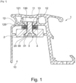
- attachment wing 12, 13 extends essentially in a transverse direction relative to the (longitudinal) axis of the profile ( figures 1 , 3 ) and in the direction of the profile axis1 ( figures 3 , 4 ).
- the attachment wing 12, 13 can extend over all or part of the length of the profile 1.
- the attachment wing can be made in one piece (without added part(s)), preferably by being integrated entirely into the profile 1, that is to say by being made directly during the manufacture of the profile 1. It can then connect two lateral sides of the profile 1, for example the two sides forming the two vertical branches of the U, by extending parallel to the opening and/or to the junction plane. It can be solid or perforated. In this case the fixing screw 3 can be screwed directly into the material of the attachment wing or into tapped holes provided for this purpose in the attachment wing.
- the clamping part 13 may have, in a preferred shape, a T-shaped cross-section, the horizontal part of the T bearing against the rear side 121 of the hooking flanges 12 and the vertical part of the T being inserted between the two flanges, preferably without extending beyond the front side 120 of the hooking flanges 12.
- the vertical part of the T comprises a thread 130 into which the screw of fixing 3, more particularly the threaded rod 31 of the latter.
- the tapping 130 can preferably extend into the horizontal part of the T, preferably beyond the latter in order to pass through the entire clamping part 13 and benefit from a greater grip through a greater screwing length.
- the damping and clamping device is constituted, as can be seen in the Figures 1 to 4 , by a stack of spring washers 4.
- Each spring washer 4 is preferably metallic.
- the damping and clamping device extends axially between a first end in contact with the front side 120 of the attachment wing 12, 13 and a second end in contact with the counterplate 2.
- the first end of the damping and clamping device is directly in contact with the front side of the hooking wing 12, 13, if applicable the front side 120 of the hooking edges 12.
- a spring washer is a washer that provides a spring function. Such a spring washer is commonly found commercially under the name of elastic washer or “Belleville” washer.
- Each spring washer 4 has a conical shape, more particularly a truncated cone, comprising a circular base.
- the first end of the damping device is formed by the circular base of the or one of the spring washer(s) 4 ( Figures 1 to 4 ).
- the conicity of the or each spring washer 4 makes it possible to ensure a homogeneous distribution of the clamping force exerted on the counterplate under the impulse of the fixing screw 3.
- the second end of the damping device 4 is formed by the circular base of one of the washers of the stack of washers 4, that is to say of the last washer of the stack starting from the first end. This characteristic makes it possible to further reinforce the clamping of the counterplate 2.
- the 4 spring washers are identical in shape and dimensions.
- the stack of spring washers 4 is clamped between the counterplate 2, under the impulse of the fixing screw 3, and the front side 120 of the attachment wing 12, 13, where appropriate of the attachment edges 12.
- the spring washers 4 maintain the clamping pressure optimally by acting as a compressed spring between two parts. This clamping compression prevents any loosening of the fixing screw 3, which ensures secure assembly. Thus, for example, during vibrations caused by repeated closing of the opening on which the profile is mounted and/or in the event of thermal expansion, the tightening of the screw is optimally maintained.
- Such a stack of 4 spring washers with the conical shape of the 4 spring washers, thus makes it possible to obtain an elastic system (or shock absorber) of great stiffness and reduced deformability. It also makes it possible to absorb thermal expansions and to compensate and/or take up clearances, for example from expansion or wear. It also makes it possible to obtain a homogeneous distribution of the support pressure and to guarantee tightening. Furthermore, these effects may vary for one or the other depending on the shape of the association/combination of the 4 spring washers. Two preferred forms of association/combination are described below. The present invention is however not limited to a particular form of association and in particular to the two forms of association described below.
- the spring washer 4 or the stack of spring washers 4 is axially crossed by the fixing screw 3.
- the fixing screw 3 can pass through the counterplate 2 by passing through the center or near the center of the latter.
- the profile and immobilization device may further comprise means against loosening of the fixing screw 3, for example of the thread lock type (not shown in the attached figures).
Landscapes
- Physics & Mathematics (AREA)
- Electromagnetism (AREA)
- Engineering & Computer Science (AREA)
- Mechanical Engineering (AREA)
- Vibration Prevention Devices (AREA)
- Shielding Devices Or Components To Electric Or Magnetic Fields (AREA)
Applications Claiming Priority (1)
| Application Number | Priority Date | Filing Date | Title |
|---|---|---|---|
| FR2308188A FR3151621B1 (fr) | 2023-07-28 | 2023-07-28 | Dispositif de profilé d’immobilisation pour système d’immobilisation de battant, plus particulièrement de porte ou fenêtre, par attraction électromagnétique |
Publications (2)
| Publication Number | Publication Date |
|---|---|
| EP4497904A1 true EP4497904A1 (de) | 2025-01-29 |
| EP4497904B1 EP4497904B1 (de) | 2026-04-01 |
Family
ID=88690113
Family Applications (1)
| Application Number | Title | Priority Date | Filing Date |
|---|---|---|---|
| EP24189185.2A Active EP4497904B1 (de) | 2023-07-28 | 2024-07-17 | Feststellprofilvorrichtung für ein flügel-rückhaltesystem, insbesondere für türen oder fenster, durch elektromagnetische anziehung |
Country Status (2)
| Country | Link |
|---|---|
| EP (1) | EP4497904B1 (de) |
| FR (1) | FR3151621B1 (de) |
Citations (4)
| Publication number | Priority date | Publication date | Assignee | Title |
|---|---|---|---|---|
| US4720128A (en) * | 1985-02-12 | 1988-01-19 | Reliable Security Systems, Inc. | Magnetic emergency exit door lock with time delay |
| US4915431A (en) * | 1989-02-27 | 1990-04-10 | Rixson-Firemark Inc. | Electromagnetic lock having a self-adjusting switch assembly for door-movement alert |
| FR2884273A1 (fr) | 2005-04-08 | 2006-10-13 | Sewosy Soc Par Actions Simplif | Dispositif de fixation d'une ventouse ou d'une contreplaque de serrure electromagnetique dans un profile |
| FR3016915A1 (fr) * | 2014-01-24 | 2015-07-31 | Cdvi Digit | Serrure electromagnetique anti-choc |
-
2023
- 2023-07-28 FR FR2308188A patent/FR3151621B1/fr active Active
-
2024
- 2024-07-17 EP EP24189185.2A patent/EP4497904B1/de active Active
Patent Citations (4)
| Publication number | Priority date | Publication date | Assignee | Title |
|---|---|---|---|---|
| US4720128A (en) * | 1985-02-12 | 1988-01-19 | Reliable Security Systems, Inc. | Magnetic emergency exit door lock with time delay |
| US4915431A (en) * | 1989-02-27 | 1990-04-10 | Rixson-Firemark Inc. | Electromagnetic lock having a self-adjusting switch assembly for door-movement alert |
| FR2884273A1 (fr) | 2005-04-08 | 2006-10-13 | Sewosy Soc Par Actions Simplif | Dispositif de fixation d'une ventouse ou d'une contreplaque de serrure electromagnetique dans un profile |
| FR3016915A1 (fr) * | 2014-01-24 | 2015-07-31 | Cdvi Digit | Serrure electromagnetique anti-choc |
Also Published As
| Publication number | Publication date |
|---|---|
| FR3151621B1 (fr) | 2025-10-03 |
| EP4497904B1 (de) | 2026-04-01 |
| FR3151621A1 (fr) | 2025-01-31 |
Similar Documents
| Publication | Publication Date | Title |
|---|---|---|
| FR3036011B1 (fr) | Systeme de fixation d'un panneau sur un longeron et structure porteuse le comprenant | |
| EP1912299B1 (de) | Elektrisches Gerät, das zur Befestigung auf einer Stützschiene vorgesehen ist, und entsprechendes Montageverfahren | |
| EP2864719A2 (de) | System zur drehbewegung eines sonnenfolgers und sonnenverfolgungsvorrichtung mit solch einem system | |
| EP0331569B1 (de) | Lagerelement mit Wegbegrenzung, besonders für Kraftfahrzeugmotoren | |
| FR2598946A1 (fr) | Dispositif de fixation d'un poincon ou d'une matrice sur un tablier d'une presse plieuse | |
| EP0309344B1 (de) | Verbindungsvorrichtung für eine Lenksäule und ein mit dieser Vorrichtung ausgestattetes Fahrzeug | |
| EP0597739A1 (de) | Anordnung zum spielfreien Befestigen von Glasscheiben | |
| EP4497904B1 (de) | Feststellprofilvorrichtung für ein flügel-rückhaltesystem, insbesondere für türen oder fenster, durch elektromagnetische anziehung | |
| FR3020612A1 (fr) | Dispositif d'ancrage d'une extremite de barre de toit pour un vehicule automobile equipe de barres de toit longitudinales | |
| EP1113128B1 (de) | Filterschliessblech für Kraftfahrzeug | |
| FR3007090A1 (fr) | Dispositif de fixation a deux ecrous et deux pattes de maintien | |
| FR2945844A1 (fr) | Dispositif de fixation d'au moins une deuxieme piece sur une premiere piece. | |
| EP0391764B1 (de) | Käfigmutter | |
| WO2013092905A1 (fr) | Element et methode de fixation d'au moins un panneau photovoltaïque sur un rail et installation et ensemble comprenant au moins un tel element | |
| EP2694826A1 (de) | Vorrichtung zur befestigung einer montageschraube an einem element vor der fixierung an einem anderen element | |
| FR3057896A1 (fr) | Montage d’une commande d’ouverture de porte du type flush | |
| FR2752793A1 (fr) | Dispositif pour fixer une barre porte-charge sur le toit d'un vehicule automobile | |
| EP1548295B1 (de) | Anordnung zur Befestigung eines Abgasanlageaufhängeelements an einem Träger am Unterboden eines Kraftfahrzeugs | |
| FR2583469A1 (fr) | Ecrou encage | |
| FR2809473A1 (fr) | Support pour la fixation d'une tablette a une paroi | |
| FR2871943A1 (fr) | Dispositif de positionnement et de fixation d'un boitier de vehicule automobile, notamment d'une batterie, et procede associe | |
| EP2116446B1 (de) | Befestigungshalterung eines Verkleidungselements eines Fahrzeugkarosserieteils, entsprechendes Verkleidungselement und Verwendung dieser Befestigungshalterung | |
| EP3938667B1 (de) | Pyrotechnische vorrichtung zum lösen von muttern | |
| FR3160921A1 (fr) | Bride de fixation d’un ressort à lames pour véhicule automobile | |
| EP3577348B1 (de) | Vorrichtung zum halten eines teils auf einer unterlage |
Legal Events
| Date | Code | Title | Description |
|---|---|---|---|
| PUAI | Public reference made under article 153(3) epc to a published international application that has entered the european phase |
Free format text: ORIGINAL CODE: 0009012 |
|
| STAA | Information on the status of an ep patent application or granted ep patent |
Free format text: STATUS: THE APPLICATION HAS BEEN PUBLISHED |
|
| AK | Designated contracting states |
Kind code of ref document: A1 Designated state(s): AL AT BE BG CH CY CZ DE DK EE ES FI FR GB GR HR HU IE IS IT LI LT LU LV MC ME MK MT NL NO PL PT RO RS SE SI SK SM TR |
|
| STAA | Information on the status of an ep patent application or granted ep patent |
Free format text: STATUS: REQUEST FOR EXAMINATION WAS MADE |
|
| 17P | Request for examination filed |
Effective date: 20250717 |
|
| GRAP | Despatch of communication of intention to grant a patent |
Free format text: ORIGINAL CODE: EPIDOSNIGR1 |
|
| STAA | Information on the status of an ep patent application or granted ep patent |
Free format text: STATUS: GRANT OF PATENT IS INTENDED |
|
| INTG | Intention to grant announced |
Effective date: 20251107 |
|
| GRAS | Grant fee paid |
Free format text: ORIGINAL CODE: EPIDOSNIGR3 |
|
| GRAA | (expected) grant |
Free format text: ORIGINAL CODE: 0009210 |
|
| STAA | Information on the status of an ep patent application or granted ep patent |
Free format text: STATUS: THE PATENT HAS BEEN GRANTED |
|
| AK | Designated contracting states |
Kind code of ref document: B1 Designated state(s): AL AT BE BG CH CY CZ DE DK EE ES FI FR GB GR HR HU IE IS IT LI LT LU LV MC ME MK MT NL NO PL PT RO RS SE SI SK SM TR |
|
| REG | Reference to a national code |
Ref country code: CH Ref legal event code: F10 Free format text: ST27 STATUS EVENT CODE: U-0-0-F10-F00 (AS PROVIDED BY THE NATIONAL OFFICE) Effective date: 20260401 Ref country code: GB Ref legal event code: FG4D Free format text: NOT ENGLISH |
|
| RIN1 | Information on inventor provided before grant (corrected) |
Inventor name: MEYNET, GAEL |
|
| REG | Reference to a national code |
Ref country code: IE Ref legal event code: FG4D Free format text: LANGUAGE OF EP DOCUMENT: FRENCH |
|
| REG | Reference to a national code |
Ref country code: DE Ref legal event code: R096 Ref document number: 602024003589 Country of ref document: DE |