EP3292805B1 - Küchenmaschinen-ergänzungskomponente mit einem stützfuss - Google Patents
Küchenmaschinen-ergänzungskomponente mit einem stützfuss Download PDFInfo
- Publication number
- EP3292805B1 EP3292805B1 EP17186256.8A EP17186256A EP3292805B1 EP 3292805 B1 EP3292805 B1 EP 3292805B1 EP 17186256 A EP17186256 A EP 17186256A EP 3292805 B1 EP3292805 B1 EP 3292805B1
- Authority
- EP
- European Patent Office
- Prior art keywords
- component
- kitchen appliance
- support foot
- attachment
- kitchen
- Prior art date
- Legal status (The legal status is an assumption and is not a legal conclusion. Google has not performed a legal analysis and makes no representation as to the accuracy of the status listed.)
- Active
Links
Images

Classifications
-
- A—HUMAN NECESSITIES
- A47—FURNITURE; DOMESTIC ARTICLES OR APPLIANCES; COFFEE MILLS; SPICE MILLS; SUCTION CLEANERS IN GENERAL
- A47J—KITCHEN EQUIPMENT; COFFEE MILLS; SPICE MILLS; APPARATUS FOR MAKING BEVERAGES
- A47J43/00—Implements for preparing or holding food, not provided for in other groups of this subclass
- A47J43/04—Machines for domestic use not covered elsewhere, e.g. for grinding, mixing, stirring, kneading, emulsifying, whipping or beating foodstuffs, e.g. power-driven
- A47J43/07—Parts or details, e.g. mixing tools, whipping tools
-
- A—HUMAN NECESSITIES
- A47—FURNITURE; DOMESTIC ARTICLES OR APPLIANCES; COFFEE MILLS; SPICE MILLS; SUCTION CLEANERS IN GENERAL
- A47J—KITCHEN EQUIPMENT; COFFEE MILLS; SPICE MILLS; APPARATUS FOR MAKING BEVERAGES
- A47J47/00—Kitchen containers, stands or the like, not provided for in other groups of this subclass; Cutting-boards, e.g. for bread
- A47J47/16—Stands, or holders for kitchen articles
-
- F—MECHANICAL ENGINEERING; LIGHTING; HEATING; WEAPONS; BLASTING
- F16—ENGINEERING ELEMENTS AND UNITS; GENERAL MEASURES FOR PRODUCING AND MAINTAINING EFFECTIVE FUNCTIONING OF MACHINES OR INSTALLATIONS; THERMAL INSULATION IN GENERAL
- F16M—FRAMES, CASINGS OR BEDS OF ENGINES, MACHINES OR APPARATUS, NOT SPECIFIC TO ENGINES, MACHINES OR APPARATUS PROVIDED FOR ELSEWHERE; STANDS; SUPPORTS
- F16M7/00—Details of attaching or adjusting engine beds, frames, or supporting-legs on foundation or base; Attaching non-moving engine parts, e.g. cylinder blocks
Definitions
- the present invention relates to a food processor supplementary component with a support leg.
- Kitchen machines such as from the FR 2 831 414 are known, usually offer a variety of functionalities. For example, they can be used for chopping vegetables, grinding nuts, whisking dough, as a juicer and / or as a meat grinder, to name just a few of the many possibilities.
- kitchen machines can be expanded by respective kitchen machine supplementary components, which can then have specific elements, for example a special filling funnel, a specially designed collecting container and / or at least one special shredding tool that is suitable for the respectively supplemented functionality / suitable.
- Such supplementary components are generally attached to at least one provided connection area of the kitchen appliance and, if necessary, connected to its motor.
- the supplementary components usually have to be supported at one or more points.
- the supplementary components can have at least one integrated or separate support foot that is to be fastened.
- a support device designed as a pot display is for example in the US 2014/0238385 A1 disclosed.
- US 2007/262213 A1 Figure 3 shows another example of a food processor add-on component with a support leg.
- the supplementary component and / or its at least one support foot must match the Type of kitchen machine provided and correctly selected by the user.
- the supplementary component with the at least one support leg according to conventional technology is only suitable for the respective kitchen appliance type, so that a user (for example, if the need changes or after an irreparable defect in the kitchen appliance) cannot switch to another type without also replacing the supplementary component.
- a suitable length can also depend on the supplementary component itself (namely on a required support height that the support foot must achieve in each case), so that for various supplementary components, if necessary. different support feet may be necessary.
- the object of the present invention is to provide a technology with which the disadvantages mentioned can be overcome and which in particular increases the flexibility of use for kitchen machine accessories.
- a support foot according to the invention for a kitchen machine supplementary component comprises at least two interconnected elements.
- a first of these elements has a component approach which attaches to the kitchen appliance supplementary component or is designed to be attached (e.g. attached) to the kitchen appliance supplementary component.
- a second of the mentioned elements has a contact end for placing on a surface (e.g. a table or kitchen worktop). The distance between the component attachment and the contact end can be adjusted (by a user).
- a length of the support foot can therefore be adjusted with the distance.
- the support foot can thus be adapted to different conditions and is particularly suitable for use for different types of kitchen machines and / or kitchen machine supplementary components.
- a support foot according to the invention is thus can be used flexibly, and the production of the kitchen machine supplementary components is simplified due to the universal usability of the support leg.
- the first element can be designed, for example, in the manner of a rod, tube or rail, and the same applies to the second element.
- the at least two elements are telescopically connected to one another.
- one of the elements forms a guide frame (for example comprises a rail or tube closed on at least three longitudinal sides) into which another of the elements is partially inserted and can be pulled out or pushed in to a variable extent.
- the elements can stabilize one another in this way, and the support foot can be produced particularly easily.
- the support foot advantageously has a blocking device which prevents it from being pulled out beyond a maximum intended extent (and in particular from loosening a connection between the at least two elements).
- the second element has an end opposite the contact end which is at least partially encompassed by another of the elements of the support foot (for example by the first element).
- the end of the second element, which is at least partially encompassed in this way and opposite the attachment end, can preferably be displaced in the interior of the further element (in particular of the first element).
- the second element has a smaller cross-section than the further or first element, so that when it is arranged or aligned as intended, soiling from above (into a space between the two elements) is prevented.
- a support foot according to the invention has a fixing mechanism for fixing one of at least two different selectable positions of the at least two elements relative to one another.
- the fixing mechanism can, for example, comprise a latching mechanism which is set up to position the first and second elements in differently adjustable positions relative to one another latch, or the fixing mechanism can comprise a clamping device which is configured to clamp the first and the second element in differently adjustable positions relative to one another.
- the fixing mechanism can comprise a lock which is preferably arranged at least partially in the interior of at least one of the elements.
- An embodiment variant is advantageous in which the fixing mechanism can be operated via at least one operating element, for example at least one button.
- the fixation can be effected, for example, by a spring and can be released by pressing on such an operating element (counter to the spring force).
- the support foot can be fixed in a suitably selected length (i.e. with a selected distance between the component attachment and the contact end from one another) and from then on (until it is adjusted again) it can be used to support the food processor supplementary component.
- the distance between the component attachment and the contact end is continuously adjustable at least within a range.
- At least two of the elements can be connected to one another, for example by means of a screw connection, in particular one of the elements can comprise a screw bolt and another a suitable thread into which the screw bolt can be screwed adjustably far.
- a support foot of such an embodiment can be used in a particularly flexible manner.
- it is also suitable for adaptation to an uneven surface and / or for use with a kitchen machine (or a kitchen machine supplementary component) with dimensions not known in advance (for example a kitchen machine of a type developed later).
- the first element is monolithic with at least one housing part of the kitchen machine supplementary component, that is to say molded onto the housing part (which can also be the entire housing);
- the housing part and the first element are at least partially in one Injection molding processes are made from plastic.
- the support foot merges into the housing part.
- connection between the kitchen machine supplementary component and the support leg is particularly solid. Since no connection mechanism is required for this, the production of the kitchen machine supplementary component and the support foot is simplified.
- a support foot according to the invention is designed as a separate part or an individual part that can be detached from the supplementary kitchen machine component.
- the support foot preferably has a support surface at its component attachment (on which the kitchen machine supplementary component can be brought to rest and which preferably has a shape that is adapted to a support area of a housing part of the kitchen machine supplementary component) and / or a fastening means for fastening of the support foot on a housing part of the food processor supplementary component.
- a fastening means can, for example, comprise a screwing device and / or a holding rail and / or a latching device.
- Such a support foot can be used in a particularly variable manner and can be used alternatively, in particular, for various kitchen machine supplementary components.
- a support foot according to the invention comprises a spring mechanism which is designed to push the component attachment and the contact end apart. In this way, the touch-down end can be driven away from the component attachment by means of the spring mechanism until it touches the ground;
- the support foot can preferably be fixed in the length thus achieved.
- the spring mechanism can be activated and / or deactivated, for example, by means of an operating element on the support foot.
- the distance between the component attachment and the contact end is preferably adjustable by at least 2 cm, more preferably at least 3 cm, the difference between a maximum possible and a minimum possible length of the support foot is therefore preferably at least 2 cm, more preferably at least 3 cm.
- the length of the support foot can thus preferably be varied by at least 2 cm, more preferably at least 3 cm. This ensures that the support leg can be used flexibly.
- a food processor supplementary component according to the invention comprises a support leg according to the invention according to one of the embodiments disclosed in this document.
- the support foot can be attached as a separate component to the kitchen machine supplementary component (preferably detachably) or it can be formed in one piece with at least one housing part of the kitchen machine supplementary component.
- FIG. 1 two kitchen machines 10, 10 'of different types are shown schematically for comparison in an intended orientation on a surface U.
- the same kitchen machine supplementary component 20 is fastened to a respective connection area 21 or 21 'of the kitchen machines 10 or 10'.
- the kitchen machine supplementary component 20 on the two kitchen machines is held in different positions relative to the underground where it are each supported by the same support foot 30 according to the invention.
- the support foot 30 comprises a first element 31 and a second element 33, which are connected to one another.
- the first element 31 comprises a component attachment 32 on which it attaches to the kitchen appliance supplementary component 20.
- This component approach can be formed in a continuous material transition, so that a housing part of the kitchen machine supplementary component 20 is monolithic with the first element 31, or the first element can be attached to the kitchen machine supplementary component 20 as a separate component (and preferably detachable) , preferably have been attached.
- the second element 33 rests on the substrate U with a placement end 34.
- the distance between the component attachment 32 and the attachment end 34 is adjustable according to the invention; As can be seen from the illustration of kitchen machines 10 and 10 'in comparison, a distance H 1 was set to support the kitchen machine supplementary component 20 attached to the kitchen machine 10, whereas a distance was set to support the kitchen machine supplementary component 20 attached to the kitchen machine 10' H 2 was discontinued. Due to the adjustability of the distance and thus the length of the support foot 30, the same support foot can be used for both kitchen appliances 10 and 10 '.
- An adjustable distance difference is preferably at least 2 cm, more preferably at least 3 cm.
- FIG. 2 is - greatly simplified - a structure of a support foot 30 according to the invention according to an exemplary embodiment of the present invention is shown in cross section.
- the support foot 30 is designed as a separate component with a first element 31 and a second element 33.
- the first element 31 has a fastening means 35 which is designed to be connected to a suitable counter-element of a kitchen appliance supplementary component for fastening the support foot.
- the first element 31 partially surrounds the second element 33;
- the second element 33 is thus displaceable within the first element 31, so that a distance H of the component attachment from a contact end 34 of the support foot is variable.
- the support leg shown here comprises a spring mechanism 36 with a spring which, with a spring force F, presses the second element away from the component attachment 32 and thus works towards increasing the distance H.
- a fixing mechanism 37 which in the present case is designed as a latching mechanism and comprises an operating element 373, which in the example shown is shaped as a lever, counteracts the spring force. Its end lying inside the first element 31 engages in a recess 371b and thus prevents the distance H from being adjusted. The second element 33 is therefore locked in the position shown relative to the first element 31.
- the latching mechanism 37 furthermore comprises a spring 372 which holds the said end of the operating element in the recess 371a. If the operating element is now actuated against the force of the spring 372, the latching is released, the second element 33 can be displaced relative to the first element 31 therein and the distance H between the component attachment 32 and the attachment end 34 can thus be adjusted. If there is a counterpressure that exceeds the spring force F by placing the attachment end 34 on a substrate (not shown), the second element 33 moves further into the first Element 31 is pressed in and the distance H is shortened, for example until the end of the operating element 373 arranged in the interior of the first element 31 engages in the recess 371c (if the operating element is released).
- the spring mechanism 36 drives the second element 33 further out of the first element 31, so that the distance H is increased, for example until the end of the operating element 373 located inside the first element 31 in the recess 371a clicks into place (again if the control element is released).
- a manual adjustment of the height H can be provided, in which the second element 33 is pulled further out of the first element or pushed into the first element.
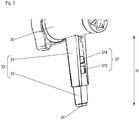
- a support foot 30 ' according to an alternative embodiment of the present invention is shown in perspective view.
- the support foot 30 ' is formed in one piece on a housing part of a kitchen machine supplementary component 20, for example by means of an injection molding process;
- the housing part and the first element 31 of the support foot are in this case preferably at least partially made of plastic.
- the component attachment 32 is formed in a continuous material transition between the housing part and the first element 31.
- first element 31 and the second element 33 are telescopically connected to one another, in the present case the second element can be partially pulled out of the first or pushed into the first element.
- first and the second element could for example be variably angled with respect to one another, for example in accordance with a folding rule principle.
- the support foot 30 ' also has a fixing mechanism 37', which comprises two buttons 374 'and 375', with which a fixing mechanism (not shown) for fixing the position of the first and second element relative to one another can be released or activated.
- a support foot 30, 30 ′ according to the invention for a kitchen machine supplementary component 20 comprises at least two interconnected elements.
- a first of the elements 31 has a component attachment 32 which attaches to the kitchen appliance supplementary component 20 or is designed to be attached to the kitchen appliance supplementary component.
- a second of the elements 33 has a placement end 34 for placement on a substrate U. The distance H, H 1 , H 2 between the component attachment 32 and the placement end 34 is adjustable.
- a food processor supplementary component 20 according to the invention comprises a support leg 30, 30 ′ according to the invention.
Landscapes
- Engineering & Computer Science (AREA)
- Food Science & Technology (AREA)
- Mechanical Engineering (AREA)
- Food-Manufacturing Devices (AREA)
Priority Applications (1)
| Application Number | Priority Date | Filing Date | Title |
|---|---|---|---|
| PL17186256T PL3292805T3 (pl) | 2016-08-26 | 2017-08-15 | Komponent uzupełniający robota kuchennego ze stopą podporową |
Applications Claiming Priority (1)
| Application Number | Priority Date | Filing Date | Title |
|---|---|---|---|
| DE102016216091.5A DE102016216091A1 (de) | 2016-08-26 | 2016-08-26 | Stützfuß für eine Küchenmaschinen-Ergänzungskomponente und Küchenmaschinen-Ergänzungskomponente mit Stützfuß |
Publications (2)
| Publication Number | Publication Date |
|---|---|
| EP3292805A1 EP3292805A1 (de) | 2018-03-14 |
| EP3292805B1 true EP3292805B1 (de) | 2021-11-24 |
Family
ID=59631621
Family Applications (1)
| Application Number | Title | Priority Date | Filing Date |
|---|---|---|---|
| EP17186256.8A Active EP3292805B1 (de) | 2016-08-26 | 2017-08-15 | Küchenmaschinen-ergänzungskomponente mit einem stützfuss |
Country Status (3)
| Country | Link |
|---|---|
| EP (1) | EP3292805B1 (pl) |
| DE (1) | DE102016216091A1 (pl) |
| PL (1) | PL3292805T3 (pl) |
Families Citing this family (1)
| Publication number | Priority date | Publication date | Assignee | Title |
|---|---|---|---|---|
| CN109662627B (zh) * | 2019-02-02 | 2024-05-10 | 南京鑫捷源新材料科技有限公司 | 一种家居规则圆形平盘用的放置设备 |
Family Cites Families (4)
| Publication number | Priority date | Publication date | Assignee | Title |
|---|---|---|---|---|
| DE1930928U (de) | 1965-06-26 | 1966-01-13 | Sueddeutsche Metallwerke G M B | Verstellvorrichtung, insbesondere fuer elektrische klein- und haushaltsgeraete. |
| FR2831414A1 (fr) * | 2001-10-31 | 2003-05-02 | Dito Sama | Dispositif de support reglable pour appareil de preparation alimentaire et appareil equipe d'un tel dispositf |
| BRPI0601993A (pt) * | 2006-05-11 | 2008-01-08 | Whirlpool Sa | pé auto-nivelador para um aparelho |
| US9648984B2 (en) * | 2013-02-25 | 2017-05-16 | Mark T. Smith | Cookware leveling solutions |
-
2016
- 2016-08-26 DE DE102016216091.5A patent/DE102016216091A1/de not_active Ceased
-
2017
- 2017-08-15 PL PL17186256T patent/PL3292805T3/pl unknown
- 2017-08-15 EP EP17186256.8A patent/EP3292805B1/de active Active
Also Published As
| Publication number | Publication date |
|---|---|
| EP3292805A1 (de) | 2018-03-14 |
| DE102016216091A1 (de) | 2018-03-01 |
| PL3292805T3 (pl) | 2022-03-07 |
Similar Documents
| Publication | Publication Date | Title |
|---|---|---|
| EP1849376B1 (de) | Höhenverstellbares Möbelbein | |
| DE19604246B4 (de) | Distanzhaltendes Implantat zum Ersetzen von fehlenden Wirbelknochen | |
| AT512748B1 (de) | Einstellvorrichtung zum Einstellen einer Lage einer Schublade | |
| DE102011100484B4 (de) | Klemmvorrichtung für Photovoltaik-Module | |
| EP2060202A2 (de) | Längenverstellbare Stütze | |
| EP2769647A1 (de) | Kinderhochstuhl | |
| EP3292806B1 (de) | Rührgefäss für eine elektromotorisch betriebene küchenmaschine | |
| EP3153063A1 (de) | Vorrichtung zu lösbaren verbindung eines in einem möbelkorpus eines möbelteils über eine führungseinheit beweglich geführten möbelauszugs mit der führungseinheit | |
| DE202014011303U1 (de) | Ein- und Ausklappvorrichtung für eine Fuß- und/oder Beinstütze eines Sitz- und/oder Liegemöbels | |
| DE202011051907U1 (de) | Hochstuhl | |
| EP3153066A1 (de) | Vorrichtung zur lösbaren verbindung eines in einem möbelkorpus eines möbelteils über eine führungseinheit beweglich geführten möbelauszugs mit der führungseinheit | |
| EP1989962A1 (de) | Synchronmechanik für Bürostühle | |
| EP3292805B1 (de) | Küchenmaschinen-ergänzungskomponente mit einem stützfuss | |
| DE9112657U1 (de) | Höhenverstellvorrichtung für Küchengeräte oder Möbel | |
| EP1516562B1 (de) | Vorrichtung zum Verstellen der Neigung eines Auszugs | |
| DE69209646T2 (de) | Gleitstütze für einen massageduschenkopf | |
| EP3292804B1 (de) | Küchenmaschinen-getriebeadapter mit verschlusshebel | |
| EP1257185B1 (de) | Verbindungselement für ein möbelstück, insbesondere für einen tisch | |
| DE102017223187B4 (de) | Standfuß für ein Küchenrührgefäß, Küchenrührgefäß mit Standfuß sowie Küchenvorrichtung | |
| EP2407675B1 (de) | Hausgerät mit einer Deckplatte und einem unter der Deckplatte angeordneten Gehäuse sowie Verfahren zur Positionierung eines Sicherungswinkels an einem unter einer Deckplatte angeordneten Gehäuses eines Hausgeräts | |
| DE3336375A1 (de) | Haushaltgeraet, insbesondere zum ein- oder unterbau geeignete geschirrspuelmaschine, waschmaschine oder dgl. | |
| DE2850599C3 (de) | Schwenkbarer Möbelfuß aus Kunststoff | |
| DE102009014552A1 (de) | Kühl- und/oder Gefriergerät | |
| EP3195771B1 (de) | Vierkantreibe | |
| EP2933539B1 (de) | Stellvorrichtung für Heizkreisventile |
Legal Events
| Date | Code | Title | Description |
|---|---|---|---|
| PUAI | Public reference made under article 153(3) epc to a published international application that has entered the european phase |
Free format text: ORIGINAL CODE: 0009012 |
|
| STAA | Information on the status of an ep patent application or granted ep patent |
Free format text: STATUS: THE APPLICATION HAS BEEN PUBLISHED |
|
| AK | Designated contracting states |
Kind code of ref document: A1 Designated state(s): AL AT BE BG CH CY CZ DE DK EE ES FI FR GB GR HR HU IE IS IT LI LT LU LV MC MK MT NL NO PL PT RO RS SE SI SK SM TR |
|
| AX | Request for extension of the european patent |
Extension state: BA ME |
|
| STAA | Information on the status of an ep patent application or granted ep patent |
Free format text: STATUS: REQUEST FOR EXAMINATION WAS MADE |
|
| 17P | Request for examination filed |
Effective date: 20180914 |
|
| RBV | Designated contracting states (corrected) |
Designated state(s): AL AT BE BG CH CY CZ DE DK EE ES FI FR GB GR HR HU IE IS IT LI LT LU LV MC MK MT NL NO PL PT RO RS SE SI SK SM TR |
|
| GRAP | Despatch of communication of intention to grant a patent |
Free format text: ORIGINAL CODE: EPIDOSNIGR1 |
|
| STAA | Information on the status of an ep patent application or granted ep patent |
Free format text: STATUS: GRANT OF PATENT IS INTENDED |
|
| INTG | Intention to grant announced |
Effective date: 20210714 |
|
| GRAS | Grant fee paid |
Free format text: ORIGINAL CODE: EPIDOSNIGR3 |
|
| GRAA | (expected) grant |
Free format text: ORIGINAL CODE: 0009210 |
|
| STAA | Information on the status of an ep patent application or granted ep patent |
Free format text: STATUS: THE PATENT HAS BEEN GRANTED |
|
| AK | Designated contracting states |
Kind code of ref document: B1 Designated state(s): AL AT BE BG CH CY CZ DE DK EE ES FI FR GB GR HR HU IE IS IT LI LT LU LV MC MK MT NL NO PL PT RO RS SE SI SK SM TR |
|
| REG | Reference to a national code |
Ref country code: GB Ref legal event code: FG4D Free format text: NOT ENGLISH |
|
| REG | Reference to a national code |
Ref country code: DE Ref legal event code: R096 Ref document number: 502017012083 Country of ref document: DE |
|
| REG | Reference to a national code |
Ref country code: AT Ref legal event code: REF Ref document number: 1449198 Country of ref document: AT Kind code of ref document: T Effective date: 20211215 |
|
| REG | Reference to a national code |
Ref country code: IE Ref legal event code: FG4D Free format text: LANGUAGE OF EP DOCUMENT: GERMAN |
|
| REG | Reference to a national code |
Ref country code: LT Ref legal event code: MG9D |
|
| REG | Reference to a national code |
Ref country code: NL Ref legal event code: MP Effective date: 20211124 |
|
| PG25 | Lapsed in a contracting state [announced via postgrant information from national office to epo] |
Ref country code: RS Free format text: LAPSE BECAUSE OF FAILURE TO SUBMIT A TRANSLATION OF THE DESCRIPTION OR TO PAY THE FEE WITHIN THE PRESCRIBED TIME-LIMIT Effective date: 20211124 Ref country code: LT Free format text: LAPSE BECAUSE OF FAILURE TO SUBMIT A TRANSLATION OF THE DESCRIPTION OR TO PAY THE FEE WITHIN THE PRESCRIBED TIME-LIMIT Effective date: 20211124 Ref country code: FI Free format text: LAPSE BECAUSE OF FAILURE TO SUBMIT A TRANSLATION OF THE DESCRIPTION OR TO PAY THE FEE WITHIN THE PRESCRIBED TIME-LIMIT Effective date: 20211124 Ref country code: BG Free format text: LAPSE BECAUSE OF FAILURE TO SUBMIT A TRANSLATION OF THE DESCRIPTION OR TO PAY THE FEE WITHIN THE PRESCRIBED TIME-LIMIT Effective date: 20220224 |
|
| PG25 | Lapsed in a contracting state [announced via postgrant information from national office to epo] |
Ref country code: IS Free format text: LAPSE BECAUSE OF FAILURE TO SUBMIT A TRANSLATION OF THE DESCRIPTION OR TO PAY THE FEE WITHIN THE PRESCRIBED TIME-LIMIT Effective date: 20220324 Ref country code: SE Free format text: LAPSE BECAUSE OF FAILURE TO SUBMIT A TRANSLATION OF THE DESCRIPTION OR TO PAY THE FEE WITHIN THE PRESCRIBED TIME-LIMIT Effective date: 20211124 Ref country code: PT Free format text: LAPSE BECAUSE OF FAILURE TO SUBMIT A TRANSLATION OF THE DESCRIPTION OR TO PAY THE FEE WITHIN THE PRESCRIBED TIME-LIMIT Effective date: 20220324 Ref country code: NO Free format text: LAPSE BECAUSE OF FAILURE TO SUBMIT A TRANSLATION OF THE DESCRIPTION OR TO PAY THE FEE WITHIN THE PRESCRIBED TIME-LIMIT Effective date: 20220224 Ref country code: NL Free format text: LAPSE BECAUSE OF FAILURE TO SUBMIT A TRANSLATION OF THE DESCRIPTION OR TO PAY THE FEE WITHIN THE PRESCRIBED TIME-LIMIT Effective date: 20211124 Ref country code: LV Free format text: LAPSE BECAUSE OF FAILURE TO SUBMIT A TRANSLATION OF THE DESCRIPTION OR TO PAY THE FEE WITHIN THE PRESCRIBED TIME-LIMIT Effective date: 20211124 Ref country code: HR Free format text: LAPSE BECAUSE OF FAILURE TO SUBMIT A TRANSLATION OF THE DESCRIPTION OR TO PAY THE FEE WITHIN THE PRESCRIBED TIME-LIMIT Effective date: 20211124 Ref country code: GR Free format text: LAPSE BECAUSE OF FAILURE TO SUBMIT A TRANSLATION OF THE DESCRIPTION OR TO PAY THE FEE WITHIN THE PRESCRIBED TIME-LIMIT Effective date: 20220225 Ref country code: ES Free format text: LAPSE BECAUSE OF FAILURE TO SUBMIT A TRANSLATION OF THE DESCRIPTION OR TO PAY THE FEE WITHIN THE PRESCRIBED TIME-LIMIT Effective date: 20211124 |
|
| PG25 | Lapsed in a contracting state [announced via postgrant information from national office to epo] |
Ref country code: SM Free format text: LAPSE BECAUSE OF FAILURE TO SUBMIT A TRANSLATION OF THE DESCRIPTION OR TO PAY THE FEE WITHIN THE PRESCRIBED TIME-LIMIT Effective date: 20211124 Ref country code: SK Free format text: LAPSE BECAUSE OF FAILURE TO SUBMIT A TRANSLATION OF THE DESCRIPTION OR TO PAY THE FEE WITHIN THE PRESCRIBED TIME-LIMIT Effective date: 20211124 Ref country code: RO Free format text: LAPSE BECAUSE OF FAILURE TO SUBMIT A TRANSLATION OF THE DESCRIPTION OR TO PAY THE FEE WITHIN THE PRESCRIBED TIME-LIMIT Effective date: 20211124 Ref country code: EE Free format text: LAPSE BECAUSE OF FAILURE TO SUBMIT A TRANSLATION OF THE DESCRIPTION OR TO PAY THE FEE WITHIN THE PRESCRIBED TIME-LIMIT Effective date: 20211124 Ref country code: DK Free format text: LAPSE BECAUSE OF FAILURE TO SUBMIT A TRANSLATION OF THE DESCRIPTION OR TO PAY THE FEE WITHIN THE PRESCRIBED TIME-LIMIT Effective date: 20211124 Ref country code: CZ Free format text: LAPSE BECAUSE OF FAILURE TO SUBMIT A TRANSLATION OF THE DESCRIPTION OR TO PAY THE FEE WITHIN THE PRESCRIBED TIME-LIMIT Effective date: 20211124 |
|
| REG | Reference to a national code |
Ref country code: DE Ref legal event code: R097 Ref document number: 502017012083 Country of ref document: DE |
|
| PLBE | No opposition filed within time limit |
Free format text: ORIGINAL CODE: 0009261 |
|
| STAA | Information on the status of an ep patent application or granted ep patent |
Free format text: STATUS: NO OPPOSITION FILED WITHIN TIME LIMIT |
|
| PG25 | Lapsed in a contracting state [announced via postgrant information from national office to epo] |
Ref country code: AL Free format text: LAPSE BECAUSE OF FAILURE TO SUBMIT A TRANSLATION OF THE DESCRIPTION OR TO PAY THE FEE WITHIN THE PRESCRIBED TIME-LIMIT Effective date: 20211124 |
|
| 26N | No opposition filed |
Effective date: 20220825 |
|
| PG25 | Lapsed in a contracting state [announced via postgrant information from national office to epo] |
Ref country code: SI Free format text: LAPSE BECAUSE OF FAILURE TO SUBMIT A TRANSLATION OF THE DESCRIPTION OR TO PAY THE FEE WITHIN THE PRESCRIBED TIME-LIMIT Effective date: 20211124 |
|
| PG25 | Lapsed in a contracting state [announced via postgrant information from national office to epo] |
Ref country code: MC Free format text: LAPSE BECAUSE OF FAILURE TO SUBMIT A TRANSLATION OF THE DESCRIPTION OR TO PAY THE FEE WITHIN THE PRESCRIBED TIME-LIMIT Effective date: 20211124 |
|
| REG | Reference to a national code |
Ref country code: CH Ref legal event code: PL |
|
| GBPC | Gb: european patent ceased through non-payment of renewal fee |
Effective date: 20220815 |
|
| PG25 | Lapsed in a contracting state [announced via postgrant information from national office to epo] |
Ref country code: LU Free format text: LAPSE BECAUSE OF NON-PAYMENT OF DUE FEES Effective date: 20220815 Ref country code: LI Free format text: LAPSE BECAUSE OF NON-PAYMENT OF DUE FEES Effective date: 20220831 Ref country code: CH Free format text: LAPSE BECAUSE OF NON-PAYMENT OF DUE FEES Effective date: 20220831 |
|
| REG | Reference to a national code |
Ref country code: BE Ref legal event code: MM Effective date: 20220831 |
|
| PG25 | Lapsed in a contracting state [announced via postgrant information from national office to epo] |
Ref country code: IT Free format text: LAPSE BECAUSE OF FAILURE TO SUBMIT A TRANSLATION OF THE DESCRIPTION OR TO PAY THE FEE WITHIN THE PRESCRIBED TIME-LIMIT Effective date: 20211124 |
|
| P01 | Opt-out of the competence of the unified patent court (upc) registered |
Effective date: 20230504 |
|
| PG25 | Lapsed in a contracting state [announced via postgrant information from national office to epo] |
Ref country code: IE Free format text: LAPSE BECAUSE OF NON-PAYMENT OF DUE FEES Effective date: 20220815 Ref country code: FR Free format text: LAPSE BECAUSE OF NON-PAYMENT OF DUE FEES Effective date: 20220831 |
|
| PG25 | Lapsed in a contracting state [announced via postgrant information from national office to epo] |
Ref country code: BE Free format text: LAPSE BECAUSE OF NON-PAYMENT OF DUE FEES Effective date: 20220831 |
|
| REG | Reference to a national code |
Ref country code: AT Ref legal event code: MM01 Ref document number: 1449198 Country of ref document: AT Kind code of ref document: T Effective date: 20220815 |
|
| PG25 | Lapsed in a contracting state [announced via postgrant information from national office to epo] |
Ref country code: GB Free format text: LAPSE BECAUSE OF NON-PAYMENT OF DUE FEES Effective date: 20220815 Ref country code: AT Free format text: LAPSE BECAUSE OF NON-PAYMENT OF DUE FEES Effective date: 20220815 |
|
| PG25 | Lapsed in a contracting state [announced via postgrant information from national office to epo] |
Ref country code: HU Free format text: LAPSE BECAUSE OF FAILURE TO SUBMIT A TRANSLATION OF THE DESCRIPTION OR TO PAY THE FEE WITHIN THE PRESCRIBED TIME-LIMIT; INVALID AB INITIO Effective date: 20170815 |
|
| PG25 | Lapsed in a contracting state [announced via postgrant information from national office to epo] |
Ref country code: CY Free format text: LAPSE BECAUSE OF FAILURE TO SUBMIT A TRANSLATION OF THE DESCRIPTION OR TO PAY THE FEE WITHIN THE PRESCRIBED TIME-LIMIT Effective date: 20211124 |
|
| PG25 | Lapsed in a contracting state [announced via postgrant information from national office to epo] |
Ref country code: MK Free format text: LAPSE BECAUSE OF FAILURE TO SUBMIT A TRANSLATION OF THE DESCRIPTION OR TO PAY THE FEE WITHIN THE PRESCRIBED TIME-LIMIT Effective date: 20211124 |
|
| PG25 | Lapsed in a contracting state [announced via postgrant information from national office to epo] |
Ref country code: TR Free format text: LAPSE BECAUSE OF FAILURE TO SUBMIT A TRANSLATION OF THE DESCRIPTION OR TO PAY THE FEE WITHIN THE PRESCRIBED TIME-LIMIT Effective date: 20211124 |
|
| PG25 | Lapsed in a contracting state [announced via postgrant information from national office to epo] |
Ref country code: MT Free format text: LAPSE BECAUSE OF FAILURE TO SUBMIT A TRANSLATION OF THE DESCRIPTION OR TO PAY THE FEE WITHIN THE PRESCRIBED TIME-LIMIT Effective date: 20211124 |
|
| PGFP | Annual fee paid to national office [announced via postgrant information from national office to epo] |
Ref country code: DE Payment date: 20250831 Year of fee payment: 9 |
|
| PGFP | Annual fee paid to national office [announced via postgrant information from national office to epo] |
Ref country code: PL Payment date: 20250801 Year of fee payment: 9 |