EP3293069A1 - Procédé et remontée mécanique destinée au transport des personnes - Google Patents
Procédé et remontée mécanique destinée au transport des personnes Download PDFInfo
- Publication number
- EP3293069A1 EP3293069A1 EP17190346.1A EP17190346A EP3293069A1 EP 3293069 A1 EP3293069 A1 EP 3293069A1 EP 17190346 A EP17190346 A EP 17190346A EP 3293069 A1 EP3293069 A1 EP 3293069A1
- Authority
- EP
- European Patent Office
- Prior art keywords
- vehicle
- vehicles
- entry point
- point
- cable car
- Prior art date
- Legal status (The legal status is an assumption and is not a legal conclusion. Google has not performed a legal analysis and makes no representation as to the accuracy of the status listed.)
- Withdrawn
Links
Images

Classifications
-
- B—PERFORMING OPERATIONS; TRANSPORTING
- B61—RAILWAYS
- B61B—RAILWAY SYSTEMS; EQUIPMENT THEREFOR NOT OTHERWISE PROVIDED FOR
- B61B1/00—General arrangement of stations, platforms, or sidings; Railway networks; Rail vehicle marshalling systems
- B61B1/02—General arrangement of stations and platforms including protection devices for the passengers
-
- B—PERFORMING OPERATIONS; TRANSPORTING
- B61—RAILWAYS
- B61B—RAILWAY SYSTEMS; EQUIPMENT THEREFOR NOT OTHERWISE PROVIDED FOR
- B61B12/00—Component parts, details or accessories not provided for in groups B61B7/00 - B61B11/00
Definitions
- the invention relates to a method for transporting people with a cable car system.
- the invention further relates to a cable car system for the transport of persons.
- Such cableway installations usually comprise a revolving conveyor rope, on which vehicles such as, for example, cabins or armchairs are moved back and forth between two cable car stations, for example terminal stations or intermediate stations.
- Known cable car plants have the disadvantage that their transport capacity is limited.
- the document AT 002199U1 discloses a cable car system with a self-contained, continuously driving conveyor rope, which is guided in the two end stations via deflection wheels and to which vehicle cabins can be coupled, wherein the vehicle cabins in the stations can be uncoupled from the hoist rope and along guide rails with respect to the speed of the hoist rope reduced speed can be moved.
- the course of the guide rails defines a guideway or a movement path of the vehicle cabins, wherein the vehicle cabins can be moved through entry and exit areas for the passengers located outside the guideway of the vehicle cabins.
- the vehicle cabins have laterally arranged doors, wherein a part of the vehicle cabins has doors arranged on the outside of the movement path which can be opened towards the outside of the movement path, and wherein the other part of the vehicle cabins has doors arranged towards the inside of the movement path, which faces the inside the movement path are openable.
- This known cable car system has the disadvantages that with respect to the trajectory overpasses and / or underpasses are required for the passengers, since an entry into the vehicle cabin, depending on the arrangement of the door, from the outside of the movement path or from the inside of the trajectory Has. Such access, with the necessary stair climbing, is perceived by passengers as unpleasant, because the access is tiring and confusing, and because the access and entry also has risks.
- the vehicle cabins are moved through the boarding or boarding area at a reduced speed, with the vehicle cabins constantly moving. This results in an entry or exit situation which, for certain passengers, carries a higher risk of complications, for example an accident risk.
- the object of the invention is a method and a cable car system for the transport of persons with a higher transport capacity, wherein the transport of persons with a plurality of vehicle cabins takes place.
- the dependent claims 2 to 8 relate to further advantageous method steps.
- the object is further achieved with a cable car system having the features of claim 9.
- the dependent claims 10 to 14 relate to further advantageously configured cable car installations.
- the inventive method is in particular solved with a method for transporting people with a cable car system comprising a hoisting rope and comprising at least four can be coupled to the hoist rope, designed as cabs vehicles, a first vehicle, a second vehicle, a third vehicle and a fourth vehicle, said all vehicles in the conveying direction are successively arranged, the vehicles are uncoupled in a cable car station from the hoisting rope and moved along a guide rail, wherein the guide rail defines a trajectory with an outwardly directed outside and an inwardly directed inside, the cable car station a first Entry point and downstream in the conveying direction comprises a second entry point, wherein the first and third vehicle is accessible only at the second entry point for passengers to boarding, and wherein the second and fourth vehicle jewe ils only is accessible at the first entry point for passengers to board.
- a cable car system for transporting people comprising a cable car station, a hoisting rope and at least four vehicles which can be coupled to and uncoupled from the hoisting rope, designed as cabs, a first vehicle, a second vehicle, a third vehicle and a fourth vehicle Vehicle, wherein all vehicles are arranged successively in the conveying direction, wherein the vehicles in the cable car station are uncoupled from the hoisting rope and along a guide rail are movable, wherein the guide rail defines a trajectory with an outwardly directed outside and an inwardly directed inside, wherein the Cableway station a first entry point and subsequently in the conveying direction comprises a second entry point, wherein the first entry point and the second entry point is arranged on the outside, so that all vehicles are accessible from the outside, and wherein the vehicles as well as the first and second entry point are controlled such that the first and third vehicle is accessible only at the second entry point for passengers to boarding, and that the second and fourth vehicle is accessible only at the first entry point
- the method according to the invention or the cable car installations according to the invention has the advantage that two access points are available in at least one cable car station for boarding the passengers, which enables an increased transport capacity.
- the inventive method is particularly then extremely advantageous if many or all passengers must be transported in the same direction, as is the case for example with the carriage of skiers or at certain operating times of the cable car installations.
- the vehicle is decelerated to the entry point at which the vehicle is accessible to the passenger for boarding, until it stops, so that the passenger can get into a stationary vehicle.
- This allows the passenger in a particularly pleasant and safe way to get into the vehicle and / or get out of the vehicle.
- This inventive method is particularly advantageous when using the cable car system in urban traffic or in an urban area, since such cable cars are used for example by older people or families with children.
- the access to the vehicle is barrier-free or designed flat, so that the access to the vehicle, similar to a lift, is flat or continuous. Since the vehicle is stationary during entry, easy and safe boarding is possible.
- the cable car is operated automatically and preferably without monitoring personnel.
- each vehicle has a vehicle opening to the outside with a door, wherein the first and the second access opening are fixed, and wherein the first and the second access opening in the conveying direction have a width substantially equal to the width of Vehicle opening corresponds, so that the vehicle is stopped so that the vehicle opening with respect to the first and second access opening is positioned.
- the vehicle can thus be entered like a lift by the vehicle or its vehicle opening is located in the access direction immediately behind the first and second access opening.
- the first or second access opening comprises a door, which is preferably opened simultaneously with the door of the positioned vehicle.
- entering the vehicle is similar to entering a lift.
- the passengers are accustomed to such access from the daily experience with lifts, so that the vehicles are safely accessible, and can be operated fully automatically.
- similar to lifts, barriers and security devices are provided so that the doors close only when no one is in the area of the doors.
- the fixed arrangement of the first and second access openings has the advantage that the location of the access opening is precisely defined, and that areas between the first and the second access opening can be provided with barriers to the path of travel, so that a passenger, except via the access openings, has no opportunity to approach and / or touch the vehicles.
- each entry point comprises an access opening oriented towards the vehicle, and then, after the access opening, a gap or a waiting room, and subsequently a control entrance.
- the passengers are admitted to the waiting room after an automatic check, for example a ticket inspection, until there are as many passengers in the waiting room as the cabin vehicle has seats. thereupon the control input is blocked until the waiting room is completely emptied.
- This method allows a particularly safe boarding of the passengers in the vehicle, especially in high passenger volumes.
- the first and the second entry point in promotion each other by several meters, so that the passengers do not influence each other at the first and second entry point, for example, do not interfere with each other.
- the first and the second entry point are arranged offset in the conveying direction by 180 °, preferably by the first entry point is arranged in the extension of the entrance of the hoisting rope, and by the second entry point is arranged in the extension of the exit of the hoisting rope.
- the method according to the invention or the cable car installations according to the invention comprises at least one cable car station with additionally two exit points, so that it is also possible to disembark the passengers with an increased capacity.
- the vehicles are braked to standstill at the exit points, in which the passengers can get off, so that the vehicles stand still during the exit.
- Fig. 1 schematically shows a cable car station 1 and a terminal of a configured as a circulating cable car cable car system for the carriage of people.
- the cableway installation comprises the cableway station 1, an endless conveyor cable 2 which is moved in the conveying direction F, and at least four vehicles 3 which can be coupled to and disengaged from the conveyor cable 2, a first vehicle 3a, a second vehicle 3b, a third vehicle 3c and a fourth vehicle 3d vehicle, wherein all vehicles 3 are arranged successively in the conveying direction F following.
- the vehicles are designed as vehicle cabins such as gondolas, wherein each nacelle preferably comprises a plurality of seats, for example 2, 4 or 8 seats.
- the cable car station 1 comprises a deflection wheel 5, on which the endless conveying cable 2 is deflected.
- the cable car station 1 comprises a guide rail 4 with an entry section 4a, along which the vehicles 3 are uncoupled from the hoisting rope 2, and an extension section 4b, along which the vehicles 3 are coupled to the conveying part 2.
- the vehicles 3 are thus in the cable car station 1 can be uncoupled from the hoist rope 2 and are along the guide rail 4 with respect to the hoisting rope 2 reduced speed movable.
- the course of the guide rail 4 defined within the cable car station 1 a trajectory of the vehicles 3.
- the guide rail 4 and the trajectory define an outwardly directed outer side 4c and an inwardly directed inside 4d.
- Each vehicle 3 has a vehicle opening 3s, which is aligned to the outside 4c of the guide rail 4 or the movement path, wherein the vehicle opening 3s is preferably provided with a closable door 3t, so that a passenger the cabin vehicle 3 via the door 3t from the outside 3c can climb and / or a passenger in the vehicle 3 can leave the vehicle 3 through the door 3t to the outside 3c out.
- the cable car station 1 comprises a first entry point 6 and, in the conveying direction F, a second entry point 7 below. Such entry points 6, 7 are also referred to as entry portals.
- the Vehicles 3 or 3a, 3b, 3c, 3d and / or the first and second access point 6,7 are controllable such that the first and third vehicle 3a, 3c is accessible only at the second entry point 7 for passengers to boarding, and in that the second and fourth vehicles 3b, 3d are accessible to passengers only at the first entry point 6 for passengers.
- the first entry point 6 is arranged in the extension of the entry section 4a of the hoisting rope 2
- the second entry point 7 is arranged in the extension of the exit section 4b of the hoist rope 2, so that the access points 6,7, as in FIG. 1 shown, arranged mutually offset in the conveying direction by 180 °.
- the access of passengers to these two access points 6,7 is thus largely separated.
- the two access points 6,7 could also be mutually offset in the extension of the entrance or the exit of the hoisting rope 2.
- the first and second access point 6,7 is advantageously, as in FIG. 1 illustrated, designed such that the moving people are channeled in the area of the entry points 6,7.
- the access points 6, 7 preferably comprise a control input 6c, 7c, subsequently a waiting room 6b, 7b, and subsequently, an access opening 6a, 7a, which is preferably designed as an automatic door.
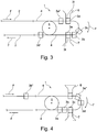
- FIGS. 1 to 4 show the process at different times.
- FIG. 1 shows four uncoupled from the hoisting rope 2 and on the guide rail 4 in the conveying direction F successively arranged vehicles 3, namely a first vehicle 3a, a second vehicle 3b, a third vehicle 3c and a fourth vehicle 3d.
- FIG. 1 also shows two vehicles 3 of a predecessor group, namely an antecedent third vehicle 3c 'and an antecedent fourth vehicle 3d'.
- the cable car station 1 comprises a first entry point 6 and downstream in the conveying direction F and a second entry point 7 spaced apart.
- the method according to the invention runs in such a way that the first and third vehicles 3a, 3c is accessible only at the second entry point 7 for passengers to boarding, and that the second and fourth vehicle 3b, 3d is accessible only at the first entry point 6 for passengers to boarding, wherein the respectively at the first and second entry point 6, 7 accessible vehicle was preferably previously completely decelerated and thus stands still at least during accessibility FIG. 1
- the second vehicle 3b are already passengers and the third vehicle 3c is empty.
- FIG. 2 shows the method at a later time during which passengers board the first and fourth vehicles 3a, 3d. These vehicles thus remain in place and thus stand still.
- the second and third vehicle 3b, 3c was moved further in the conveying direction F.
- the preceding third vehicle 3c ', the previous fourth vehicle 3d', and the subsequent first vehicle 3a has been moved.
- FIG. 3 shows the method at a later time, during which the passengers in the first and fourth vehicle 3a, 3d are boarded, and the doors 3t of these vehicles are closed. These vehicles thus still remain in place and thus stand still.
- the second and third vehicle 3b, 3c was moved further in the conveying direction F.
- the preceding third vehicle 3c 'and the previous fourth vehicle 3d' has been moved.
- the following first vehicle 3a "stands still.
- FIG. 4 shows the method at a later time, during which the passengers are in the first, second and fourth vehicles 3a, 3b, 3d, the doors 3t of these vehicles are closed, and these vehicles are moved to the position shown.
- the second vehicle 3b passes through the second access area 7 without stopping.
- the third vehicle 3c is stopped in front of the second access area 7 so that passengers can board.
- the following first vehicle 3a is further moved past the first access area 6 without stopping at the first access area 6.
- the following second vehicle 3b approaches the first access area 7 and stops at the first access area 7 in a next process step, not shown, so that passengers can board.
- the four vehicles 3, namely the first vehicle 3a, the second vehicle 3b, the third vehicle 3c and the fourth vehicle 3d in the FIGS. 1 to 4 The method shown is now repeated constantly, so that the first and third vehicle 3a, 3c and the subsequent first and third vehicle 3a ", 3c" is accessible only at the second entry point 7 for passengers to boarding, and that the second and fourth vehicle 3b, 3d and the subsequent second and fourth vehicle 3b ", 3d" respectively only accessible at the first entry point 6 for passengers to board.
- the vehicles 3 located at the first and second entry points 6, 7 are accessible in the same time window.
- the vehicles can, in one possible method, move slowly in the conveying direction F during the boarding of the passengers at the first and second entry points 6, 7.
- the vehicles 3 located at the first and second access points 6, 7 are stopped for entry, advantageously such that the door opening 3s or the vehicle door 3t is arranged directly opposite the access opening 6a, 7a.
- each vehicle 3 has a vehicle opening 3s with a door 3t toward the outside 4c, the first and the second access openings 6a, 7a being fixedly arranged, the first and second access openings having a width in the conveying direction that is in the Substantially corresponds to the width of the vehicle opening, wherein the vehicle 3 is stopped such that the vehicle opening 3s is positioned opposite the first and second access opening 6a, 7a.
- the vehicles 3 drive at the entry point at which no entry takes place without stopping.
- the first and the second entry point 6, 7 are also used as exit points, so that if there are passengers in the arriving vehicle, they first get off at the first or second entry point 6, 7 before the waiting passengers enter the afterwards get emptied vehicle.
- a first and a second exit point 8.9 is provided, to which passengers can get off.
- these exit points are arranged opposite the first and the second entry point 6, 7, so that the passengers entering and exiting move in the same direction.
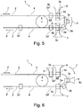
- each vehicle 3 additionally has a door 3u which can be opened towards the inside 4d of the guide rail 4 or the movement path.
- the cable car station 1 as in FIG. 6 represented, a first exit point 8 and in the conveying direction F subsequently a second exit point 9, both of which are aligned to the outside 4c out, the first and third vehicle 3a, 3c can be left only at the second exit point 9 of passengers, and wherein the second and fourth vehicle 3b, 3d can be left only at the first exit point 8 of passengers.
- FIG. 5 shows an embodiment in which is entered at the first and the second entry point 6,7 from the outside 4c in the vehicle 3, and is dropped on the opposite inner side 4d of the vehicle 3.
- FIG. 6 shows an embodiment in which the first and the second exit point 8,9 offset in the conveying direction F with respect to the first and the second entry point 6,7 are arranged, which gives the advantage that at the first and the second entry point 6.7 from the outside 4c is entered in the vehicle 3, and on the first and the second exit point 8,9 on the same outside 4c is dropped out.
Landscapes
- Engineering & Computer Science (AREA)
- Transportation (AREA)
- Mechanical Engineering (AREA)
- Platform Screen Doors And Railroad Systems (AREA)
Applications Claiming Priority (2)
| Application Number | Priority Date | Filing Date | Title |
|---|---|---|---|
| EP16188221 | 2016-09-09 | ||
| EP17153806 | 2017-01-30 |
Publications (1)
| Publication Number | Publication Date |
|---|---|
| EP3293069A1 true EP3293069A1 (fr) | 2018-03-14 |
Family
ID=59846479
Family Applications (1)
| Application Number | Title | Priority Date | Filing Date |
|---|---|---|---|
| EP17190346.1A Withdrawn EP3293069A1 (fr) | 2016-09-09 | 2017-09-11 | Procédé et remontée mécanique destinée au transport des personnes |
Country Status (1)
| Country | Link |
|---|---|
| EP (1) | EP3293069A1 (fr) |
Cited By (2)
| Publication number | Priority date | Publication date | Assignee | Title |
|---|---|---|---|---|
| CN112001831A (zh) * | 2019-05-27 | 2020-11-27 | 丰田自动车株式会社 | 信息处理设备、信息处理方法和非暂时性计算机可读存储介质 |
| CN112711720A (zh) * | 2020-12-31 | 2021-04-27 | 广州宸祺出行科技有限公司 | 一种降低出行成本的上车点推荐方法及系统 |
Citations (5)
| Publication number | Priority date | Publication date | Assignee | Title |
|---|---|---|---|---|
| JPH03132465A (ja) * | 1989-10-19 | 1991-06-05 | Anzen Sakudo Kk | 循環式索道の乗降方法及びそのシステム |
| WO1996029223A1 (fr) * | 1995-03-22 | 1996-09-26 | Denis Creissels | Teleporteur ayant deux emplacements d'embarquement |
| AT2199U1 (de) * | 1996-10-10 | 1998-06-25 | Doppelmayr & Sohn | Seilbahnanlage mit einem in sich geschlossenen förderseil |
| EP2199172A2 (fr) * | 2008-12-18 | 2010-06-23 | Innova Patent GmbH | Cabine et installation de téléphérique, la cabine comportant une porte sur chaque face longitudinale |
| WO2015184478A2 (fr) * | 2014-06-02 | 2015-12-10 | Innova Patent Gmbh | Téléphérique de transport de personnes |
-
2017
- 2017-09-11 EP EP17190346.1A patent/EP3293069A1/fr not_active Withdrawn
Patent Citations (5)
| Publication number | Priority date | Publication date | Assignee | Title |
|---|---|---|---|---|
| JPH03132465A (ja) * | 1989-10-19 | 1991-06-05 | Anzen Sakudo Kk | 循環式索道の乗降方法及びそのシステム |
| WO1996029223A1 (fr) * | 1995-03-22 | 1996-09-26 | Denis Creissels | Teleporteur ayant deux emplacements d'embarquement |
| AT2199U1 (de) * | 1996-10-10 | 1998-06-25 | Doppelmayr & Sohn | Seilbahnanlage mit einem in sich geschlossenen förderseil |
| EP2199172A2 (fr) * | 2008-12-18 | 2010-06-23 | Innova Patent GmbH | Cabine et installation de téléphérique, la cabine comportant une porte sur chaque face longitudinale |
| WO2015184478A2 (fr) * | 2014-06-02 | 2015-12-10 | Innova Patent Gmbh | Téléphérique de transport de personnes |
Cited By (2)
| Publication number | Priority date | Publication date | Assignee | Title |
|---|---|---|---|---|
| CN112001831A (zh) * | 2019-05-27 | 2020-11-27 | 丰田自动车株式会社 | 信息处理设备、信息处理方法和非暂时性计算机可读存储介质 |
| CN112711720A (zh) * | 2020-12-31 | 2021-04-27 | 广州宸祺出行科技有限公司 | 一种降低出行成本的上车点推荐方法及系统 |
Similar Documents
| Publication | Publication Date | Title |
|---|---|---|
| EP2157004B1 (fr) | Installation de téléphérique | |
| EP1849674A1 (fr) | Installation de téléphérique à câble tracteur avec véhicules débrayables | |
| EP3148858B1 (fr) | Téléphérique de transport de personnes | |
| EP3221199B1 (fr) | Téléphérique | |
| DE3206630A1 (de) | Befoerderungsanlage mit einem seilgeschleppten fahrzeug | |
| DE69402585T2 (de) | Transportanlage auf einem Bahnkörper mit mehreren Gleisabschnitten | |
| EP2848489A1 (fr) | Installation de téléphérique destinée au transport de personnes | |
| EP0275403B1 (fr) | Installation de téléphérique | |
| EP3914497B1 (fr) | Détection de passage pour téléphérique | |
| DE2646828A1 (de) | Durchgehendes befoerderungssystem | |
| EP1878631B1 (fr) | Installation de téléphérique dotée d'au moins un câble tracteur | |
| DE2651983C3 (de) | Anlage zur Beförderung von Personen | |
| EP2199172B1 (fr) | Cabine et installation de téléphérique, la cabine comportant une porte sur chaque face longitudinale | |
| EP3293069A1 (fr) | Procédé et remontée mécanique destinée au transport des personnes | |
| DE102018202557A1 (de) | Kollisionsverhinderung zwischen Fahrkörben | |
| AT411045B (de) | Anlage zur beförderung von personen | |
| EP2062798B1 (fr) | Téléphérique avec un siège suspendu au câble de portage et de traction | |
| EP0798189B1 (fr) | Installation pour transporter des personnes et/ou des marchandises | |
| DE1755442A1 (de) | Anlage fuer den kontinuierlichen Transport von Personen | |
| AT503900A2 (de) | Seilbahnanlage mit mindestens einem förderseil | |
| AT526242B1 (de) | Parksystem für eine Umlaufseilbahn | |
| DE102017200641A1 (de) | oFahrzeug zur Personenbeförderung | |
| AT403680B (de) | Transporteinrichtung, insbesondere für den personen-nahverkehr | |
| EP3292033A1 (fr) | Véhicule pour un téléphérique à câble sans fin | |
| EP4699888A1 (fr) | Station de téléphérique à transporteur continu |
Legal Events
| Date | Code | Title | Description |
|---|---|---|---|
| PUAI | Public reference made under article 153(3) epc to a published international application that has entered the european phase |
Free format text: ORIGINAL CODE: 0009012 |
|
| AK | Designated contracting states |
Kind code of ref document: A1 Designated state(s): AL AT BE BG CH CY CZ DE DK EE ES FI FR GB GR HR HU IE IS IT LI LT LU LV MC MK MT NL NO PL PT RO RS SE SI SK SM TR |
|
| AX | Request for extension of the european patent |
Extension state: BA ME |
|
| STAA | Information on the status of an ep patent application or granted ep patent |
Free format text: STATUS: THE APPLICATION IS DEEMED TO BE WITHDRAWN |
|
| 18D | Application deemed to be withdrawn |
Effective date: 20180915 |