EP3293080B1 - Engin agricole - Google Patents
Engin agricole Download PDFInfo
- Publication number
- EP3293080B1 EP3293080B1 EP17168177.8A EP17168177A EP3293080B1 EP 3293080 B1 EP3293080 B1 EP 3293080B1 EP 17168177 A EP17168177 A EP 17168177A EP 3293080 B1 EP3293080 B1 EP 3293080B1
- Authority
- EP
- European Patent Office
- Prior art keywords
- assembly
- chassis
- centring
- centering
- working machine
- Prior art date
- Legal status (The legal status is an assumption and is not a legal conclusion. Google has not performed a legal analysis and makes no representation as to the accuracy of the status listed.)
- Active
Links
Images

Classifications
-
- B—PERFORMING OPERATIONS; TRANSPORTING
- B62—LAND VEHICLES FOR TRAVELLING OTHERWISE THAN ON RAILS
- B62D—MOTOR VEHICLES; TRAILERS
- B62D21/00—Understructures, i.e. chassis frame on which a vehicle body may be mounted
- B62D21/12—Understructures, i.e. chassis frame on which a vehicle body may be mounted assembled from readily detachable parts
-
- B—PERFORMING OPERATIONS; TRANSPORTING
- B62—LAND VEHICLES FOR TRAVELLING OTHERWISE THAN ON RAILS
- B62D—MOTOR VEHICLES; TRAILERS
- B62D65/00—Designing, manufacturing, e.g. assembling, facilitating disassembly, or structurally modifying motor vehicles or trailers, not otherwise provided for
- B62D65/02—Joining sub-units or components to, or positioning sub-units or components with respect to, body shell or other sub-units or components
- B62D65/024—Positioning of sub-units or components with respect to body shell or other sub-units or components
-
- F—MECHANICAL ENGINEERING; LIGHTING; HEATING; WEAPONS; BLASTING
- F16—ENGINEERING ELEMENTS AND UNITS; GENERAL MEASURES FOR PRODUCING AND MAINTAINING EFFECTIVE FUNCTIONING OF MACHINES OR INSTALLATIONS; THERMAL INSULATION IN GENERAL
- F16B—DEVICES FOR FASTENING OR SECURING CONSTRUCTIONAL ELEMENTS OR MACHINE PARTS TOGETHER, e.g. NAILS, BOLTS, CIRCLIPS, CLAMPS, CLIPS OR WEDGES; JOINTS OR JOINTING
- F16B19/00—Bolts without screw-thread; Pins, including deformable elements; Rivets
- F16B19/02—Bolts or sleeves for positioning of machine parts, e.g. notched taper pins, fitting pins, sleeves, eccentric positioning rings
Definitions
- the invention relates to an agricultural work machine, in particular a tractor, with a chassis according to the preamble of claim 1, and a method for disassembling an assembly of a chassis according to claim 7.
- Modern agricultural machines such as tractors usually have a chassis, which is at least partially formed by a plurality of interconnected assemblies.
- Assemblies can be, for example, a drive motor or a gearbox of the working machine.
- Such interconnected assemblies form part of the chassis and contribute significantly to its rigidity and load capacity.
- an oil pan which can form part of the assembly "drive motor” to connect such with the drive motor and at least one adjacent module, that this also forms a supporting component of the chassis of the machine.
- Connecting means for connecting components are known from NL7611626A and the DE102008021905A1 known.
- Such connected to a drive motor oil pan is from the DE 699 29 394 T2 known.
- an engine block and an oil pan are bolted together and with a front suspension.
- the engine forms a part of the chassis of the tractor
- the front suspension forms a front extension of the chassis, to which, inter alia, the front wheels and the steering mechanism are fastened.
- a gap is provided between the front suspension and the oil pan, which is bridged by the use of arranged in the Vorderachsaufh Kunststoffung sleeves, so as to make a tolerance compensation during assembly can.
- the disadvantage here is that a tolerance compensation between the components, although in the longitudinal direction can be made, but no alignment of the components to each other in a direction transverse to the longitudinal direction, whereby, for example, a precise alignment of a front PTO is difficult.
- a disassembly of individual components of the chassis without disassembly of the entire chassis is made impossible by the fixed installation and the arrangement of the sleeves.
- An agricultural working machine in particular a tractor, comprises a chassis which has at least a first assembly and a second assembly, wherein an assembly comprises at least one component, and wherein the chassis has at least one centering means, which in a mounted state of the chassis in a Centering between two juxtaposed, and in particular releasably interconnected, assemblies is arranged, wherein in the centering the centering is at least partially accommodated in the juxtaposed assemblies in recesses formed therefor.
- the centering means in the mounted state of the chassis, can be moved from the centering position into a disassembling position, in which the centering means is received in only one of the assemblies.
- centering means when the chassis is mounted, a more precise alignment of the assemblies, in particular transversely to a longitudinal direction of the chassis and / or the working machine, can take place relative to each other.
- the introduction of the centering in the disassembly position with mounted chassis also allows disassembly of individual components of an assembly, such as the oil pan, without the associated assembly or the chassis must be completely disassembled. This has the advantage that in addition to an improved assembly by more precise alignment of the modules to each other even easier maintenance of an agricultural machine can be guaranteed.
- a recess for completely receiving the centering in one of the modules is formed as a through hole. Due to the configuration of the recess for completely receiving the centering means as a through hole through a component and / or an assembly, can be manufactured together with the access to the centering means also cost-effective, the recess for complete reception of the centering means.
- the centering radially on the inside and / or end a connection profile, through which the centering means can be connected to a pulling device.
- the connection profile of the centering means enables a connection of the centering means with a pulling device, in particular a positive and / or positive connection. This offers the advantage that the centering means is axially displaceable in both directions, so for example not only beaten in one direction but can also be pulled with the pulling device in the disassembly position.
- the centering means has an at least partially rotationally symmetrical cross-section, and is designed in particular in the form of a sleeve or a cylindrical pin. Due to the rotationally symmetrical shape, both the centering means and the recesses can be produced inexpensively. In addition, the use of, for example, standardized sleeves or cylindrical pins offers the possibility of further reducing costs.
- the centering means has an at least partially rotationally asymmetrical cross-section.
- a centering means may have, at least in sections, a rotationally asymmetric cross section.
- This rotationally asymmetrical cross section can cooperate with a correspondingly formed recess, whereby a rotation of the centering means about a longitudinal axis by positive engagement with the recess, in particular during a displacement, can be avoided.
- This has the advantage that a displacement of the centering can also be done with a simple pulling device.
- the centering means is displaceable in an assembled state of the chassis from the disassembly position to the centering position.
- the pulling device in the form of a threaded rod, a screw or in the form of a Abziehwerkmaschinees, in particular with a striking handle formed.
- a simple pulling device may, for example, be a screw or a threaded rod with a nut, which is positively and / or non-positively connected to the centering means. This has the advantage that a displacement of the centering can be done without special tools.
- a so-called puller, in particular with a percussion handle, which can be positively and / or positively connected to a centering means, has the advantage that a displacement of the centering can be done without great expenditure of time.
- the invention relates to a method for disassembling an assembly or a component of an assembly of a chassis of an agricultural machine, comprising the steps of connecting a pulling device each having a arranged in a centering centering a chassis of an agricultural machine; Displacing the at least one centering means from the centering position to a disassembling position; and dismantling the assembly and / or the component of the assembly.
- a centering centering means when the chassis is mounted, a more precise alignment of the assemblies, in particular transversely to a longitudinal direction of the chassis and / or the working machine, can take place relative to each other.
- the introduction of the centering in the disassembly position with mounted chassis also has the advantage that disassembly of individual components of an assembly, such as the oil pan, can be done without the associated assembly or the chassis must be completely disassembled.
- a connecting a pulling device each with a arranged in a disassembly position centering of the mounted chassis and a displacement of the at least one centering of the disassembly position are provided in the centering position.
- Fig. 1 is shown in a side view of a chassis 10 of an agricultural machine according to the invention in the form of a tractor.
- the working machine has a drive motor 12 which is connected at the bottom to an oil pan 14 and at the rear to a coupling housing 16.
- the drive motor 12, the oil pan 14 and the clutch housing 16 thereby form a first assembly 18 of the chassis 10.
- the drive motor 12, the oil pan 14 and the clutch housing 16 are components of the first assembly 18.
- a second assembly 20 of the chassis 10 is replaced by a Front axle assembly formed, of which only a front frame 22 is shown, on which, for example, a front axle of the working machine can be arranged.
- a gear block 24 is arranged, which forms a third assembly 26 of the chassis 10.
- the assemblies 18, 20, 26 are detachably connected to each other, for example by screw 28, and form a supporting part of the chassis 10.
- the second assembly 20 is arranged on the first assembly 18, that the front frame 22 is fixed by means of screw 28 to the drive motor 12 and the oil pan 14.
- the centering means 30 is arranged between the first assembly 18 and the second assembly 20 in a centering position 32, in which the centering means 30 in each of the first and second assembly 18, 20 is partially arranged. In this way, a precise alignment of the first and second assembly 18, 20, in particular transversely to a longitudinal direction, can be effected.
- the centering means 30 can be brought in a mounted state of the chassis 10 of the centering position 32 in a disassembly position in which the centering means 30 is received only in one of the assemblies 18, 20.
- the centering means 30 is shown arranged in the centering position 32 adjacent to a screw 28.
- the centering means 30 may bridge a gap 34 in the centering position 32, which may be formed, for example, to compensate for tolerances in the longitudinal direction between the first and second component 18, 20.
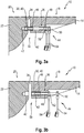
- the centering means 30 is accessible via a through-bore 36.
- the through bore 36 ( Fig. 2b ) is in the first assembly 18, in particular the oil pan 14 is formed. Through a cover 38, the through hole 36 is closed to prevent the ingress of dirt.
- the centering means 30 may, for example, have a rotationally symmetrical cross-section and be formed in the form of a sleeve or a cylindrical pin 40.
- the centering means 30 in the form of a cylindrical pin 40 bridges in the centering position 32 the gap 34 between the first and the second assembly 18, 20.
- the centering means 30 is in each case partially in a recess 42 of the first and second assembly 18, 20, in particular the oil pan 14 and the front frame 22.
- the recess 42 in the front frame 22 is formed in the form of a blind hole, in which the centering means 30 can be inserted, for example, during assembly of the chassis 10.
- the recess 42 in the oil pan is formed as a through hole 36, which has areas with different diameters.
- the recess 42 in the first assembly 18, in particular the oil pan 14, is designed such that the centering means 30 at least at one of the second assembly 20 facing the end is fully absorbable.
- the complete inclusion of the centering means 30 in an assembly 18, 20, 26 in an assembled state of the chassis 10 allows disassembly of individual components 12, 14, 16, 22 of an assembly 18, 20, 26 without the chassis 10 and / or assemblies 18th , 20, 26 have to be completely dismantled. As a result, for example, disassembly and repair or replacement of the oil pan 14 can take place without the first assembly 18 having to be completely separated from the chassis 10.
- connection profile 46 which is in the form of an internal thread.
- a connection profile 46 can also be arranged at the end on the centering means 30 in order to enable a non-positive and / or positive connection with a pulling device 44.
- the illustrated pulling device 44 is designed in the form of a screw 48, which is connected through the through-bore 36 with the connecting profile 46, that is to say the internal thread, of the centering means 30.
- the screw 48 has at its end a screw head 50, and on the thread of the screw 48, a nut 52 is movably arranged.
- the screw head 50 and the nut 52 can be actuated by tools 54, in particular wrench, or fixed in a rotationally fixed manner.
- the mother 50 in FIG. 3b can thereby be brought into abutment with the first assembly 18, in particular the oil pan 14 and while holding the screw head 52 non-rotatably, the screw 48 and thus the centering means 30 can be moved out of the through-bore 36.
- the centering means 30 is thereby until the complete inclusion in the recess 42 in the first assembly 18, in particular the oil pan 14, displaced and thus in a disassembly position 56 can be brought.
- oil pan 14 can be disassembled as a single component of the first assembly 18. It is particularly advantageous if, during a subsequent assembly of, for example, the oil pan 14, it is first aligned precisely with the other components 22 and / or assemblies 18, 20 prior to tightening the screw connections 28. This can be achieved by a displacement of the centering means 30 from the disassembly position 56 into the centering position 32, whereby the component 14 can be precisely aligned even after disassembly again.
- a centering means 30 may at least partially have a rotationally asymmetric cross section, for example, by a, at least partially, oval or polygonal cross section.
- This rotationally asymmetrical cross section can cooperate in a form-fitting manner with the recess 42 of an assembly 18, 20, 26 in order to prevent the centering means 30 from rotating.
- the centering means 30 may be formed in one piece or several pieces, and, for example, to generate a rotationally asymmetric cross-section circumferentially have a feather key, which can act positively with a correspondingly formed recess 42 together.
- An alternative pulling device 44 may be in the form of a so-called peeling tool, which is likewise connectable to the centering means 30 via a screw connection.
- a percussion handle is used, which is moved along the Abziehwerkmaschinees up to a stop, which can be pulled out by the impact of the percussion handle on the stop the Abziehwerkmaschine with the centering of a recess 42.
Landscapes
- Engineering & Computer Science (AREA)
- Chemical & Material Sciences (AREA)
- Combustion & Propulsion (AREA)
- Transportation (AREA)
- Mechanical Engineering (AREA)
- Manufacturing & Machinery (AREA)
- Agricultural Machines (AREA)
Claims (7)
- Machine de travail agricole, en particulier tracteur, comprenant un châssis (10) qui comporte au moins un premier groupe fonctionnel (18) et un second groupe fonctionnel (20), un groupe fonctionnel (18, 20, 26) comprenant au moins une partie fonctionnelle (12, 14, 16, 22, 24), et le châssis (10) comprenant au moins un moyen de centrage (30) qui, dans un état monté du châssis (10), est disposé dans une position centrée (32) entre deux groupes fonctionnels disposés l'un contre l'autre (18, 20, 26), dans la position centrée (32) le moyen de centrage (30) étant reçu au moins en partie dans les groupes fonctionnels disposés l'un contre l'autre (18, 20, 26) dans des évidements (42) ménagés à cet effet, caractérisée en ce que, dans l'état monté du châssis (10), le moyen de centrage (30) peut être déplacé d'une position centrée (32) vers une position de démontage (56) dans laquelle le moyen de centrage (30) n'est reçu que dans un des groupes fonctionnels (18, 20, 26), le moyen de centrage (30) comportant radialement à l'intérieur et/ou à son extrémité un profil de liaison (46) par l'intermédiaire duquel le moyen de centrage (30) peut être relié à un dispositif de serrage (44).
- Machine de travail selon la revendication 1, caractérisée en ce qu'un évidement (42) est ménagé dans un des groupes fonctionnels (18, 20, 26) sous la forme d'un perçage débouchant (36) pour recevoir entièrement le moyen de centrage (30).
- Machine de travail selon la revendication 1 ou 2, caractérisée en ce que le moyen de centrage (30) présente une section transversale conçue au moins en partie avec une symétrie de révolution et est conçu en particulier sous la forme d'un manchon ou d'une tige cylindrique (40).
- Machine de travail selon une des revendications précédentes, caractérisée en ce que le moyen de centrage (30) présente une section transversale conçue au moins en partie sans symétrie de révolution.
- Machine de travail selon une des revendications précédentes, caractérisée en ce que, dans un état monté du châssis (10), le moyen de centrage (30) est déplaçable de la position de démontage (56) vers la position centrée (32).
- Machine de travail selon une des revendications précédentes, caractérisée en ce que le dispositif de serrage (44) est conçu sous la forme d'une tige filetée, d'une vis (48) ou sous forme d'outil de desserrage, en particulier avec une poignée de frappe.
- Procédé de démontage d'un groupe fonctionnel ou d'une partie fonctionnelle d'un groupe fonctionnel d'un châssis (10) d'une machine de travail agricole, en particulier selon une des revendications 1 à 6, comprenant les étapes consistant à- relier un dispositif de serrage (44) à un moyen de centrage (30), disposé en position centrée (32), d'un châssis (30) d'une machine de travail agricole ;- déplacer le au moins un moyen de centrage (30) de la position centrée (32) vers une position de démontage (56) ;- démonter le groupe fonctionnel (18, 20, 26) et/ou une partie fonctionnelle (12, 14, 16, 22) du groupe fonctionnel (18, 20, 26).- relier un dispositif de serrage (44) à un moyen de centrage (30), disposé dans une position de démontage (56), du châssis monté (10) ;- déplacer le au moins un moyen de centrage (30) de la position de démontage (56) vers la position centrée (32).
Applications Claiming Priority (1)
| Application Number | Priority Date | Filing Date | Title |
|---|---|---|---|
| DE102016117000.3A DE102016117000A1 (de) | 2016-09-09 | 2016-09-09 | Landwirtschaftliche Arbeitsmaschine |
Publications (2)
| Publication Number | Publication Date |
|---|---|
| EP3293080A1 EP3293080A1 (fr) | 2018-03-14 |
| EP3293080B1 true EP3293080B1 (fr) | 2019-09-25 |
Family
ID=58638713
Family Applications (1)
| Application Number | Title | Priority Date | Filing Date |
|---|---|---|---|
| EP17168177.8A Active EP3293080B1 (fr) | 2016-09-09 | 2017-04-26 | Engin agricole |
Country Status (2)
| Country | Link |
|---|---|
| EP (1) | EP3293080B1 (fr) |
| DE (1) | DE102016117000A1 (fr) |
Family Cites Families (5)
| Publication number | Priority date | Publication date | Assignee | Title |
|---|---|---|---|---|
| FR2328869A1 (fr) * | 1975-10-22 | 1977-05-20 | Stein Industrie | Dispositif d'assemblage de deux brides planes de flexibilites differentes ou non |
| GB9824341D0 (en) | 1998-11-07 | 1998-12-30 | New Holland Uk Ltd | Securing spaced elements to one other |
| DE102008021905A1 (de) * | 2007-05-25 | 2008-11-27 | Heidelberger Druckmaschinen Ag | Zentrierbuchse |
| US20130322985A1 (en) * | 2012-05-31 | 2013-12-05 | United Technologies Corporation | Retention assembly including sleeve |
| FR2995372A1 (fr) * | 2012-09-13 | 2014-03-14 | Lisi Aerospace | Dispositif de fixation |
-
2016
- 2016-09-09 DE DE102016117000.3A patent/DE102016117000A1/de not_active Withdrawn
-
2017
- 2017-04-26 EP EP17168177.8A patent/EP3293080B1/fr active Active
Non-Patent Citations (1)
| Title |
|---|
| None * |
Also Published As
| Publication number | Publication date |
|---|---|
| EP3293080A1 (fr) | 2018-03-14 |
| DE102016117000A1 (de) | 2018-03-15 |
Similar Documents
| Publication | Publication Date | Title |
|---|---|---|
| DE29522251U1 (de) | Einrichtung zum Klemmen einer Lageranordnung an eine verlängerte Welle | |
| EP2008774B1 (fr) | Dispositif destiné à retirer une buse d'injection | |
| DE3135689C2 (de) | Kupplung zum lösbaren Verbinden einer unterteilten Antriebswelle eines Kraftfahrzeuges | |
| EP3156666A1 (fr) | Systeme de fixation d'un element de machine | |
| DE102010017592B4 (de) | Verfahren und Vorrichtung zur spanlosen axial umformenden Ausbildung einer Verzahnung mit angeformten Spitzen an einem Werkstück | |
| EP1936109B1 (fr) | Dispositif de forage à entrainement rotatif | |
| EP1690700B1 (fr) | Dispositif pour variable démontage et montage des pièces d'axe | |
| EP3293080B1 (fr) | Engin agricole | |
| DE102016213811B4 (de) | Werkzeug und Verfahren zum Ein- und Ausziehen von Bauteilen | |
| EP3611404B1 (fr) | Pignon d'entraînement à chaîne | |
| DE102012012293B4 (de) | Vorrichtung zum Umformen eines Werkstücks | |
| DE102007011617A1 (de) | Verfahren zur Befestigung einer Gewindebuchse in einer Platte sowie das Werkzeug hierzu | |
| DE102009052141A1 (de) | Manipulator für Schmiedemaschinen | |
| DE20316274U1 (de) | Vorrichtung zur Montage einer Ölspritzdüse | |
| EP1452758B1 (fr) | Raccord à brides pour arbre et procédé pour faire un tel raccord | |
| EP0567750B1 (fr) | Machine pour le travail du sol, en particulier herse rotative | |
| EP3417151B1 (fr) | Ensemble cylindre de moteur orc | |
| DE19611526C1 (de) | Vorrichtung zur gelenkigen Verbindung | |
| DE202018101550U1 (de) | Stellhebel für ein Motorgerät | |
| DE102008058384A1 (de) | Zahnradanordnung | |
| DE102016219823B3 (de) | Schneckenmaschine-Getriebe-Anordnung und Verfahren zur Wartung von Schneckenwellen einer derartigen Schneckenmaschine-Getriebe-Anordnung | |
| DE102008027494A1 (de) | Mehrteilige Walze | |
| DE202024104808U1 (de) | Werkzeug zur Demontage einer Riemenscheibe von der dazugehörigen sich drehenden Welle; insbesondere zur Demontage einer Riemenscheibe, die mit einem Dämpfer für Drehschwingungen von der Motorwelle eines Fahrzeugs ausgestattet ist | |
| DE102014223082A1 (de) | Getriebegehäuse mit abnehmbarem Nebengehäuseteil zur erleichterten Gummilagermontage | |
| DE20004486U1 (de) | Vorrichtung zum Lösen einer in einer Aufnahmebohrung eines Lagerauges o.dgl. fest sitzenden Schraube |
Legal Events
| Date | Code | Title | Description |
|---|---|---|---|
| PUAI | Public reference made under article 153(3) epc to a published international application that has entered the european phase |
Free format text: ORIGINAL CODE: 0009012 |
|
| STAA | Information on the status of an ep patent application or granted ep patent |
Free format text: STATUS: THE APPLICATION HAS BEEN PUBLISHED |
|
| AK | Designated contracting states |
Kind code of ref document: A1 Designated state(s): AL AT BE BG CH CY CZ DE DK EE ES FI FR GB GR HR HU IE IS IT LI LT LU LV MC MK MT NL NO PL PT RO RS SE SI SK SM TR |
|
| AX | Request for extension of the european patent |
Extension state: BA ME |
|
| STAA | Information on the status of an ep patent application or granted ep patent |
Free format text: STATUS: REQUEST FOR EXAMINATION WAS MADE |
|
| 17P | Request for examination filed |
Effective date: 20180914 |
|
| RBV | Designated contracting states (corrected) |
Designated state(s): AL AT BE BG CH CY CZ DE DK EE ES FI FR GB GR HR HU IE IS IT LI LT LU LV MC MK MT NL NO PL PT RO RS SE SI SK SM TR |
|
| GRAP | Despatch of communication of intention to grant a patent |
Free format text: ORIGINAL CODE: EPIDOSNIGR1 |
|
| STAA | Information on the status of an ep patent application or granted ep patent |
Free format text: STATUS: GRANT OF PATENT IS INTENDED |
|
| INTG | Intention to grant announced |
Effective date: 20190627 |
|
| GRAS | Grant fee paid |
Free format text: ORIGINAL CODE: EPIDOSNIGR3 |
|
| GRAA | (expected) grant |
Free format text: ORIGINAL CODE: 0009210 |
|
| STAA | Information on the status of an ep patent application or granted ep patent |
Free format text: STATUS: THE PATENT HAS BEEN GRANTED |
|
| AK | Designated contracting states |
Kind code of ref document: B1 Designated state(s): AL AT BE BG CH CY CZ DE DK EE ES FI FR GB GR HR HU IE IS IT LI LT LU LV MC MK MT NL NO PL PT RO RS SE SI SK SM TR |
|
| REG | Reference to a national code |
Ref country code: GB Ref legal event code: FG4D Free format text: NOT ENGLISH |
|
| REG | Reference to a national code |
Ref country code: CH Ref legal event code: EP |
|
| REG | Reference to a national code |
Ref country code: AT Ref legal event code: REF Ref document number: 1183560 Country of ref document: AT Kind code of ref document: T Effective date: 20191015 |
|
| REG | Reference to a national code |
Ref country code: IE Ref legal event code: FG4D Free format text: LANGUAGE OF EP DOCUMENT: GERMAN |
|
| REG | Reference to a national code |
Ref country code: DE Ref legal event code: R096 Ref document number: 502017002373 Country of ref document: DE |
|
| REG | Reference to a national code |
Ref country code: NL Ref legal event code: MP Effective date: 20190925 |
|
| PG25 | Lapsed in a contracting state [announced via postgrant information from national office to epo] |
Ref country code: HR Free format text: LAPSE BECAUSE OF FAILURE TO SUBMIT A TRANSLATION OF THE DESCRIPTION OR TO PAY THE FEE WITHIN THE PRESCRIBED TIME-LIMIT Effective date: 20190925 Ref country code: LT Free format text: LAPSE BECAUSE OF FAILURE TO SUBMIT A TRANSLATION OF THE DESCRIPTION OR TO PAY THE FEE WITHIN THE PRESCRIBED TIME-LIMIT Effective date: 20190925 Ref country code: SE Free format text: LAPSE BECAUSE OF FAILURE TO SUBMIT A TRANSLATION OF THE DESCRIPTION OR TO PAY THE FEE WITHIN THE PRESCRIBED TIME-LIMIT Effective date: 20190925 Ref country code: BG Free format text: LAPSE BECAUSE OF FAILURE TO SUBMIT A TRANSLATION OF THE DESCRIPTION OR TO PAY THE FEE WITHIN THE PRESCRIBED TIME-LIMIT Effective date: 20191225 Ref country code: NO Free format text: LAPSE BECAUSE OF FAILURE TO SUBMIT A TRANSLATION OF THE DESCRIPTION OR TO PAY THE FEE WITHIN THE PRESCRIBED TIME-LIMIT Effective date: 20191225 Ref country code: FI Free format text: LAPSE BECAUSE OF FAILURE TO SUBMIT A TRANSLATION OF THE DESCRIPTION OR TO PAY THE FEE WITHIN THE PRESCRIBED TIME-LIMIT Effective date: 20190925 |
|
| REG | Reference to a national code |
Ref country code: LT Ref legal event code: MG4D |
|
| PG25 | Lapsed in a contracting state [announced via postgrant information from national office to epo] |
Ref country code: RS Free format text: LAPSE BECAUSE OF FAILURE TO SUBMIT A TRANSLATION OF THE DESCRIPTION OR TO PAY THE FEE WITHIN THE PRESCRIBED TIME-LIMIT Effective date: 20190925 Ref country code: GR Free format text: LAPSE BECAUSE OF FAILURE TO SUBMIT A TRANSLATION OF THE DESCRIPTION OR TO PAY THE FEE WITHIN THE PRESCRIBED TIME-LIMIT Effective date: 20191226 Ref country code: LV Free format text: LAPSE BECAUSE OF FAILURE TO SUBMIT A TRANSLATION OF THE DESCRIPTION OR TO PAY THE FEE WITHIN THE PRESCRIBED TIME-LIMIT Effective date: 20190925 |
|
| PG25 | Lapsed in a contracting state [announced via postgrant information from national office to epo] |
Ref country code: ES Free format text: LAPSE BECAUSE OF FAILURE TO SUBMIT A TRANSLATION OF THE DESCRIPTION OR TO PAY THE FEE WITHIN THE PRESCRIBED TIME-LIMIT Effective date: 20190925 Ref country code: NL Free format text: LAPSE BECAUSE OF FAILURE TO SUBMIT A TRANSLATION OF THE DESCRIPTION OR TO PAY THE FEE WITHIN THE PRESCRIBED TIME-LIMIT Effective date: 20190925 Ref country code: EE Free format text: LAPSE BECAUSE OF FAILURE TO SUBMIT A TRANSLATION OF THE DESCRIPTION OR TO PAY THE FEE WITHIN THE PRESCRIBED TIME-LIMIT Effective date: 20190925 Ref country code: IT Free format text: LAPSE BECAUSE OF FAILURE TO SUBMIT A TRANSLATION OF THE DESCRIPTION OR TO PAY THE FEE WITHIN THE PRESCRIBED TIME-LIMIT Effective date: 20190925 Ref country code: RO Free format text: LAPSE BECAUSE OF FAILURE TO SUBMIT A TRANSLATION OF THE DESCRIPTION OR TO PAY THE FEE WITHIN THE PRESCRIBED TIME-LIMIT Effective date: 20190925 Ref country code: PT Free format text: LAPSE BECAUSE OF FAILURE TO SUBMIT A TRANSLATION OF THE DESCRIPTION OR TO PAY THE FEE WITHIN THE PRESCRIBED TIME-LIMIT Effective date: 20200127 Ref country code: PL Free format text: LAPSE BECAUSE OF FAILURE TO SUBMIT A TRANSLATION OF THE DESCRIPTION OR TO PAY THE FEE WITHIN THE PRESCRIBED TIME-LIMIT Effective date: 20190925 Ref country code: AL Free format text: LAPSE BECAUSE OF FAILURE TO SUBMIT A TRANSLATION OF THE DESCRIPTION OR TO PAY THE FEE WITHIN THE PRESCRIBED TIME-LIMIT Effective date: 20190925 |
|
| PG25 | Lapsed in a contracting state [announced via postgrant information from national office to epo] |
Ref country code: SM Free format text: LAPSE BECAUSE OF FAILURE TO SUBMIT A TRANSLATION OF THE DESCRIPTION OR TO PAY THE FEE WITHIN THE PRESCRIBED TIME-LIMIT Effective date: 20190925 Ref country code: SK Free format text: LAPSE BECAUSE OF FAILURE TO SUBMIT A TRANSLATION OF THE DESCRIPTION OR TO PAY THE FEE WITHIN THE PRESCRIBED TIME-LIMIT Effective date: 20190925 Ref country code: IS Free format text: LAPSE BECAUSE OF FAILURE TO SUBMIT A TRANSLATION OF THE DESCRIPTION OR TO PAY THE FEE WITHIN THE PRESCRIBED TIME-LIMIT Effective date: 20200224 Ref country code: CZ Free format text: LAPSE BECAUSE OF FAILURE TO SUBMIT A TRANSLATION OF THE DESCRIPTION OR TO PAY THE FEE WITHIN THE PRESCRIBED TIME-LIMIT Effective date: 20190925 |
|
| REG | Reference to a national code |
Ref country code: DE Ref legal event code: R097 Ref document number: 502017002373 Country of ref document: DE |
|
| PG2D | Information on lapse in contracting state deleted |
Ref country code: IS |
|
| PG25 | Lapsed in a contracting state [announced via postgrant information from national office to epo] |
Ref country code: DK Free format text: LAPSE BECAUSE OF FAILURE TO SUBMIT A TRANSLATION OF THE DESCRIPTION OR TO PAY THE FEE WITHIN THE PRESCRIBED TIME-LIMIT Effective date: 20190925 Ref country code: IS Free format text: LAPSE BECAUSE OF FAILURE TO SUBMIT A TRANSLATION OF THE DESCRIPTION OR TO PAY THE FEE WITHIN THE PRESCRIBED TIME-LIMIT Effective date: 20200126 |
|
| PLBE | No opposition filed within time limit |
Free format text: ORIGINAL CODE: 0009261 |
|
| STAA | Information on the status of an ep patent application or granted ep patent |
Free format text: STATUS: NO OPPOSITION FILED WITHIN TIME LIMIT |
|
| 26N | No opposition filed |
Effective date: 20200626 |
|
| PG25 | Lapsed in a contracting state [announced via postgrant information from national office to epo] |
Ref country code: MC Free format text: LAPSE BECAUSE OF FAILURE TO SUBMIT A TRANSLATION OF THE DESCRIPTION OR TO PAY THE FEE WITHIN THE PRESCRIBED TIME-LIMIT Effective date: 20190925 Ref country code: SI Free format text: LAPSE BECAUSE OF FAILURE TO SUBMIT A TRANSLATION OF THE DESCRIPTION OR TO PAY THE FEE WITHIN THE PRESCRIBED TIME-LIMIT Effective date: 20190925 |
|
| REG | Reference to a national code |
Ref country code: CH Ref legal event code: PL |
|
| PG25 | Lapsed in a contracting state [announced via postgrant information from national office to epo] |
Ref country code: LU Free format text: LAPSE BECAUSE OF NON-PAYMENT OF DUE FEES Effective date: 20200426 Ref country code: CH Free format text: LAPSE BECAUSE OF NON-PAYMENT OF DUE FEES Effective date: 20200430 Ref country code: LI Free format text: LAPSE BECAUSE OF NON-PAYMENT OF DUE FEES Effective date: 20200430 |
|
| REG | Reference to a national code |
Ref country code: BE Ref legal event code: MM Effective date: 20200430 |
|
| PG25 | Lapsed in a contracting state [announced via postgrant information from national office to epo] |
Ref country code: BE Free format text: LAPSE BECAUSE OF NON-PAYMENT OF DUE FEES Effective date: 20200430 |
|
| PG25 | Lapsed in a contracting state [announced via postgrant information from national office to epo] |
Ref country code: IE Free format text: LAPSE BECAUSE OF NON-PAYMENT OF DUE FEES Effective date: 20200426 |
|
| GBPC | Gb: european patent ceased through non-payment of renewal fee |
Effective date: 20210426 |
|
| PG25 | Lapsed in a contracting state [announced via postgrant information from national office to epo] |
Ref country code: GB Free format text: LAPSE BECAUSE OF NON-PAYMENT OF DUE FEES Effective date: 20210426 |
|
| PG25 | Lapsed in a contracting state [announced via postgrant information from national office to epo] |
Ref country code: TR Free format text: LAPSE BECAUSE OF FAILURE TO SUBMIT A TRANSLATION OF THE DESCRIPTION OR TO PAY THE FEE WITHIN THE PRESCRIBED TIME-LIMIT Effective date: 20190925 Ref country code: MT Free format text: LAPSE BECAUSE OF FAILURE TO SUBMIT A TRANSLATION OF THE DESCRIPTION OR TO PAY THE FEE WITHIN THE PRESCRIBED TIME-LIMIT Effective date: 20190925 Ref country code: CY Free format text: LAPSE BECAUSE OF FAILURE TO SUBMIT A TRANSLATION OF THE DESCRIPTION OR TO PAY THE FEE WITHIN THE PRESCRIBED TIME-LIMIT Effective date: 20190925 |
|
| PG25 | Lapsed in a contracting state [announced via postgrant information from national office to epo] |
Ref country code: MK Free format text: LAPSE BECAUSE OF FAILURE TO SUBMIT A TRANSLATION OF THE DESCRIPTION OR TO PAY THE FEE WITHIN THE PRESCRIBED TIME-LIMIT Effective date: 20190925 |
|
| REG | Reference to a national code |
Ref country code: AT Ref legal event code: MM01 Ref document number: 1183560 Country of ref document: AT Kind code of ref document: T Effective date: 20220426 |
|
| P01 | Opt-out of the competence of the unified patent court (upc) registered |
Effective date: 20230516 |
|
| PG25 | Lapsed in a contracting state [announced via postgrant information from national office to epo] |
Ref country code: AT Free format text: LAPSE BECAUSE OF NON-PAYMENT OF DUE FEES Effective date: 20220426 |
|
| PGFP | Annual fee paid to national office [announced via postgrant information from national office to epo] |
Ref country code: DE Payment date: 20250422 Year of fee payment: 9 |
|
| PGFP | Annual fee paid to national office [announced via postgrant information from national office to epo] |
Ref country code: FR Payment date: 20250425 Year of fee payment: 9 |