EP3417151B1 - Ensemble cylindre de moteur orc - Google Patents
Ensemble cylindre de moteur orc Download PDFInfo
- Publication number
- EP3417151B1 EP3417151B1 EP17710113.6A EP17710113A EP3417151B1 EP 3417151 B1 EP3417151 B1 EP 3417151B1 EP 17710113 A EP17710113 A EP 17710113A EP 3417151 B1 EP3417151 B1 EP 3417151B1
- Authority
- EP
- European Patent Office
- Prior art keywords
- crosshead
- connecting rod
- piston rod
- cylinder assembly
- piston
- Prior art date
- Legal status (The legal status is an assumption and is not a legal conclusion. Google has not performed a legal analysis and makes no representation as to the accuracy of the status listed.)
- Active
Links
Images

Classifications
-
- F—MECHANICAL ENGINEERING; LIGHTING; HEATING; WEAPONS; BLASTING
- F01—MACHINES OR ENGINES IN GENERAL; ENGINE PLANTS IN GENERAL; STEAM ENGINES
- F01B—MACHINES OR ENGINES, IN GENERAL OR OF POSITIVE-DISPLACEMENT TYPE, e.g. STEAM ENGINES
- F01B9/00—Reciprocating-piston machines or engines characterised by connections between pistons and main shafts, not specific to groups F01B1/00 - F01B7/00
- F01B9/02—Reciprocating-piston machines or engines characterised by connections between pistons and main shafts, not specific to groups F01B1/00 - F01B7/00 with crankshaft
-
- F—MECHANICAL ENGINEERING; LIGHTING; HEATING; WEAPONS; BLASTING
- F16—ENGINEERING ELEMENTS AND UNITS; GENERAL MEASURES FOR PRODUCING AND MAINTAINING EFFECTIVE FUNCTIONING OF MACHINES OR INSTALLATIONS; THERMAL INSULATION IN GENERAL
- F16C—SHAFTS; FLEXIBLE SHAFTS; ELEMENTS OR CRANKSHAFT MECHANISMS; ROTARY BODIES OTHER THAN GEARING ELEMENTS; BEARINGS
- F16C11/00—Pivots; Pivotal connections
- F16C11/04—Pivotal connections
- F16C11/045—Pivotal connections with at least a pair of arms pivoting relatively to at least one other arm, all arms being mounted on one pin
-
- F—MECHANICAL ENGINEERING; LIGHTING; HEATING; WEAPONS; BLASTING
- F16—ENGINEERING ELEMENTS AND UNITS; GENERAL MEASURES FOR PRODUCING AND MAINTAINING EFFECTIVE FUNCTIONING OF MACHINES OR INSTALLATIONS; THERMAL INSULATION IN GENERAL
- F16C—SHAFTS; FLEXIBLE SHAFTS; ELEMENTS OR CRANKSHAFT MECHANISMS; ROTARY BODIES OTHER THAN GEARING ELEMENTS; BEARINGS
- F16C5/00—Crossheads; Constructions of connecting-rod heads or piston-rod connections rigid with crossheads
-
- F—MECHANICAL ENGINEERING; LIGHTING; HEATING; WEAPONS; BLASTING
- F16—ENGINEERING ELEMENTS AND UNITS; GENERAL MEASURES FOR PRODUCING AND MAINTAINING EFFECTIVE FUNCTIONING OF MACHINES OR INSTALLATIONS; THERMAL INSULATION IN GENERAL
- F16C—SHAFTS; FLEXIBLE SHAFTS; ELEMENTS OR CRANKSHAFT MECHANISMS; ROTARY BODIES OTHER THAN GEARING ELEMENTS; BEARINGS
- F16C9/00—Bearings for crankshafts or connecting-rods; Attachment of connecting-rods
- F16C9/04—Connecting-rod bearings; Attachments thereof
-
- F—MECHANICAL ENGINEERING; LIGHTING; HEATING; WEAPONS; BLASTING
- F16—ENGINEERING ELEMENTS AND UNITS; GENERAL MEASURES FOR PRODUCING AND MAINTAINING EFFECTIVE FUNCTIONING OF MACHINES OR INSTALLATIONS; THERMAL INSULATION IN GENERAL
- F16C—SHAFTS; FLEXIBLE SHAFTS; ELEMENTS OR CRANKSHAFT MECHANISMS; ROTARY BODIES OTHER THAN GEARING ELEMENTS; BEARINGS
- F16C2360/00—Engines or pumps
-
- F—MECHANICAL ENGINEERING; LIGHTING; HEATING; WEAPONS; BLASTING
- F16—ENGINEERING ELEMENTS AND UNITS; GENERAL MEASURES FOR PRODUCING AND MAINTAINING EFFECTIVE FUNCTIONING OF MACHINES OR INSTALLATIONS; THERMAL INSULATION IN GENERAL
- F16C—SHAFTS; FLEXIBLE SHAFTS; ELEMENTS OR CRANKSHAFT MECHANISMS; ROTARY BODIES OTHER THAN GEARING ELEMENTS; BEARINGS
- F16C2360/00—Engines or pumps
- F16C2360/22—Internal combustion engines
Definitions
- the invention relates to a cylinder assembly of an ORC engine with a crosshead for the articulated connection of a piston rod of a piston guided in a working cylinder with a connecting rod of the ORC engine, wherein the crosshead is movable in a guide in the longitudinal direction of the piston rod.
- the invention is based on the object of reducing the effort required for repair or maintenance work on a cylinder assembly.
- the present invention provides a new cylinder assembly of the type mentioned at the outset which is easy to assemble and is characterized in that the crosshead can be detached from the connecting rod in the direction of the working cylinder without complete or partial disassembly of the guide.
- the guide leaves enough space for dismantling the crosshead by axially displacing a connecting rod bolt and/or according to the invention, the crosshead can be dismantled into parts for dismantling from the connecting rod.
- the crosshead is so small compared to the diameter of a bush-shaped guide that the connecting rod bolt connecting the crosshead and the connecting rod can be pushed out of its pivot bearings far enough to the side.
- the crosshead is formed from at least two half-shells enclosing the connecting rod bolts connecting the crosshead and the connecting rod.
- an assembly comprising the crosshead, the piston rod and the piston can be decoupled in its entirety from the connecting rod.
- the crosshead comprises fork legs which have through holes for the connecting rod bolt and between which the free end of the connecting rod is arranged.
- the crosshead is secured against rotation about the longitudinal axis of the piston rod by the guide. This advantageously allows torques exerted on the said structural unit to be absorbed during assembly work.
- the guide preferably has a guide bushing coaxial with the longitudinal axis of the piston rod with guide rails protruding from the inner wall of the bushing.
- the guide rails can, for example, form pairs of diametrically opposed guide surfaces, in particular flat guide surfaces, for the crosshead.
- the fork legs protrude from a preferably conical section of the crosshead that can be connected to the piston rod.
- the conical shape of the crosshead ensures that the piston force is evenly transmitted and distributed via the piston rod to the fork legs.
- a detachable connection in particular a screw connection, between at least one of the fork legs and the section.
- the crosshead can thus be dismantled into parts, which makes it possible to disassemble it even if the connecting rod bolt has limited mobility.
- the piston rod is designed as a hollow body.
- the crosshead can be screwed to the piston rod and the piston rod to the piston via threads coaxial with the longitudinal axis of the piston rod.
- the thread diameter of the screw connection of the piston rod to the crosshead is larger than the thread diameter of the screw connection of the piston rod to the piston. This enables the piston to be detached separately from the piston rod without loosening the screw connection between the piston rod and the crosshead.
- a dowel pin connection is made in addition to the screw connections mentioned.
- the dowel pin connection ensures that the piston always assumes the same rotational position in relation to the crosshead.
- the assembly 1 of an ORC engine shown comprises a working cylinder 2 in which a piston 3 and a piston rod 4 rigidly connected to the piston 3 are guided.
- the piston rod 4 is connected to a crosshead 6 which is guided within a bushing 7 coaxial with the working cylinder 2 in a direction parallel to the longitudinal direction of the piston rod 4 and is in turn connected to a connecting rod 8 which moves the crosshead 6.
- the bushing 7 is a cylinder bushing of an internal combustion engine, which forms a basis for the ORC engine, wherein the working cylinder 1 and the structural unit of the ORC engine forming the piston 3, the piston rod 4 and the crosshead 6 take the place of the piston and the cylinder head of the internal combustion engine.
- connection of the connecting rod 8 with the crosshead 6 is provided by a connecting rod bolt 9, which is rotatably mounted in a bearing bush insert 10 of the connecting rod 8.
- the connecting rod pin 9 projects with its two ends into a bearing bush insert 11 or 12, wherein the bearing bush inserts 11, 12 are each arranged in a through-opening of a fork leg 13 or 14 of the crosshead 6.
- the connecting rod pin 9 is axially fixed in the bush inserts 10 to 12 by a boundary wall 15 in the opening of the fork leg 14 and a snap ring 16 accommodated in a groove in the opening of the fork leg 13.
- the crosshead 6 comprises a conical section 17 which merges integrally into the fork leg 13.
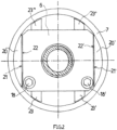
- the fork leg 14 is connected by screws 18 and 18' ( Fig. 2 ) detachably connected to the conical section 17.
- diametrically opposed guide rails 20 and 20' are attached to the inner wall of the bushing 7, each of which has two flat guide surfaces 21 and 21' arranged at a distance from one another.
- the crosshead 6 slides against these guide surfaces 21, 21' with corresponding flat contact surfaces 22 and 22'.
- crosshead is secured against rotation about the longitudinal axis of the piston rod 4 by the contact against the four guide surfaces.
- the partially hollow conical section 17 is connected to the piston rod 4 via an intermediate piece 24.
- a screw 25 connects the conical section 17 to the intermediate piece 24.
- An end section 26 of the intermediate piece 24 has an external thread which is screwed to an internal thread of the piston rod 4 designed as a hollow body.
- the intermediate piece 24 could also be formed integrally with the conical section 17 or the piston rod 4.
- the sleeve 7 is connected to a crankcase (not shown) and the working cylinder 2 is connected coaxially to the bushing 7 to a cylinder bank (not shown) which may have several such bushings 7.
- the complete assembly consisting of the piston 3, the piston rod 4 and the crosshead 6 can be dismantled by loosening the connection between the crosshead 6 and the connecting rod 8 as follows: First, the snap ring 16 is removed using a tool inserted into the bushing 7. Due to the free space between the relevant pin end and the inner wall of the bushing 7, the connecting rod pin 9 can then be axially displaced so far that the other pin end of the connecting rod pin 9 no longer engages in the bearing bush section 12. In the next disassembly step, the screws 18 and 18' are loosened and the fork leg 14 is removed.
- the guide pins 23, 23', 23" and 23′′′ leave sufficient space in the bushing 7 to carry out the above-mentioned assembly steps, so that they can remain in place during assembly. In the example shown, they are permanently pinned to the bushing 7.
- This guide which absorbs torques around the bushing axis, easily enables separate disassembly of only the piston 3 when the assembly consisting of the piston 3, the piston rod 4 and the crosshead 6 is installed.
- the actuating element 5 normally strikes the piston 3 near the top dead center of the piston 3 vertically in the center of the piston. Transverse forces resulting from deviations in the impact position and the impact angle within the tolerance limits are by guiding the above-mentioned assembly in the working cylinder 2 via the guide ring 19 and in the bushing 7 through the rails 20, 20' as well as the inner wall of the bushing 7, against which the guide pins 23, 23', 23", 23′′′ rest.
Landscapes
- Engineering & Computer Science (AREA)
- General Engineering & Computer Science (AREA)
- Mechanical Engineering (AREA)
- Pistons, Piston Rings, And Cylinders (AREA)
Claims (12)
- Ensemble de cylindre (1) pour un moteur COR avec une crosse (6) pour une liaison articulée d'une tige de piston (4) d'un piston (3) guidé dans un cylindre de travail (2) avec une tige de bielle (8) du moteur COR, sachant que la crosse (6) peut être mobile dans le sens longitudinal de la tige de piston (4) dans un guidage (7) en forme de douille, caractérisé en ce que
la crosse (6) peut être séparée sans démontage complet ou partiel du guidage de la tige de bielle (8) en direction du cylindre de travail (2), sachant qu'avec la séparation de la crosse (6) de la tige de bielle (8) une unité de construction formée par la crosse (6), la tige de piston (4) et le piston (3) peut être découplée dans sa totalité de la tige de bielle (8) et sachant qu'à travers le guidage de l'espace libre est laissé pour le démontage de la crosse (6) par déplacement axial d'un boulon de bielle (9) reliant la crosse (6) et la tige de bielle (8), la crosse (6) étant si petite en comparaison du diamètre du guidage (7) en forme de douille que le boulon de bielle (9) peut être glissé latéralement suffisamment loin hors de ses logements de rotation. - Ensemble de cylindre (1) selon la revendication 1, caractérisé en ce que
la crosse (6) peut être décomposée en pièces (17, 13, 14) à des fins de démontage, la crosse (6) étant formée d'au moins deux demi-coques entourant un boulon de bielle (9) reliant la crosse (6) et la tige de bielle (8) - Ensemble de cylindre (1) selon la revendication 1 ou 2, caractérisé en ce que
la crosse (6) comprend des ouvertures de passage pour les branches de fourche (13, 14) comportant le boulon de bielle (9) entre lesquelles vient se mettre en place l'extrémité libre de la tige de bielle (8). - Ensemble de cylindre (1) selon la revendication 3, caractérisé en ce que
les branches de fourche (13, 14) s'écartent d'une section (17) de la crosse (6) de préférence conique pouvant être reliée à la tige de piston (4). - Ensemble de cylindre (1) selon la revendication 4, caractérisé en ce qu'
une liaison amovible, en particulier par vis (18, 18'), existe entre au moins une des branches de fourche (13, 14) et la section conique (17). - Ensemble de cylindre (1) selon l'une quelconque des revendications 1 à 5, caractérisé en ce que
la crosse (6) est sécurisée par le guidage envers toute rotation autour de l'axe longitudinal de la tige de piston (4). - Ensemble de cylindre (1) selon l'une quelconque des revendications 1 à 6, caractérisé en ce que
le guidage comporte une douille de guidage (7) coaxiale à l'axe longitudinal de la tige de piston (4) avec des glissières (20, 20') en saillie de la paroi intérieure de douille. - Ensemble de cylindre (1) selon la revendication 7, caractérisé en ce que
des surfaces de guidage (21, 21') diamétralement opposées l'une à l'autre sont formées par les glissières (20, 20'), le cas échéant par des paires de surfaces de guidage en particulier planes. - Ensemble de cylindre (1) selon l'une quelconque des revendications 1 à 8, caractérisé en ce que
la tige de piston (4) est constituée sous la forme d'un corps creux. - Ensemble de cylindre (1) selon l'une quelconque des revendications 1 à 9,
caractérisé en ce que
la crosse (6) peut être vissée à la tige de piston (4) et la tige de piston (4) au piston (3) par le filetage coaxial à l'axe longitudinal de la tige de piston (4). - Ensemble de cylindre (1) selon la revendication 10, caractérisé en ce que
le diamètre de filetage de l'assemblage par vissage de la tige de piston avec la crosse (4) est plus grand que le diamètre de filetage de l'assemblage par vissage de la tige de piston (4) avec le piston (3). - Ensemble de cylindre (1) selon la revendication 10 ou 11, caractérisé en ce qu'
une liaison à goupille d'assemblage est réalisée en plus des assemblages par vissage.
Applications Claiming Priority (2)
| Application Number | Priority Date | Filing Date | Title |
|---|---|---|---|
| DE102016102649.2A DE102016102649A1 (de) | 2016-02-16 | 2016-02-16 | Zylinderbaugruppe eines ORC-Motors |
| PCT/DE2017/100085 WO2017140296A1 (fr) | 2016-02-16 | 2017-02-06 | Ensemble cylindre de moteur orc |
Publications (3)
| Publication Number | Publication Date |
|---|---|
| EP3417151A1 EP3417151A1 (fr) | 2018-12-26 |
| EP3417151B1 true EP3417151B1 (fr) | 2024-12-18 |
| EP3417151C0 EP3417151C0 (fr) | 2024-12-18 |
Family
ID=58266323
Family Applications (1)
| Application Number | Title | Priority Date | Filing Date |
|---|---|---|---|
| EP17710113.6A Active EP3417151B1 (fr) | 2016-02-16 | 2017-02-06 | Ensemble cylindre de moteur orc |
Country Status (5)
| Country | Link |
|---|---|
| US (1) | US20190032487A1 (fr) |
| EP (1) | EP3417151B1 (fr) |
| CN (1) | CN108699906B (fr) |
| DE (2) | DE102016102649A1 (fr) |
| WO (1) | WO2017140296A1 (fr) |
Families Citing this family (1)
| Publication number | Priority date | Publication date | Assignee | Title |
|---|---|---|---|---|
| CN111946486B (zh) * | 2020-07-07 | 2021-04-09 | 北京工业大学 | 一种无泵自压缩有机朗肯循环发动机 |
Family Cites Families (21)
| Publication number | Priority date | Publication date | Assignee | Title |
|---|---|---|---|---|
| GB190621999A (en) * | 1906-10-05 | 1907-10-03 | George William Morrison | Improvements in and relating to Internal Combustion Motors. |
| GB191517953A (en) * | 1915-12-23 | 1918-02-21 | Harry Ralph Ricardo | Improvements in or relating to Pistons for Internal Combustion Engines. |
| GB119157A (en) | 1917-12-07 | 1918-09-26 | John William Draper | Improvements in or connected with Piston Crossheads and in Means for Guiding the same. |
| NL30562C (fr) * | 1931-05-05 | 1933-08-15 | ||
| US2057158A (en) * | 1935-03-25 | 1936-10-13 | Robert C Moffitt | Differential piston connecting linkage |
| GB485590A (en) * | 1936-11-21 | 1938-05-23 | Stephen Evans Alley | Improvements in or relating to steam-propelled vehicles |
| US2171554A (en) * | 1937-01-11 | 1939-09-05 | Hedges Motor Company | Rod connection and cross head guide |
| GB498455A (en) * | 1938-02-16 | 1939-01-09 | Werkspoor Nv | Improvements in and relating to single-acting crosshead combustion engines |
| US2463174A (en) * | 1946-05-29 | 1949-03-01 | William J Hasselberg | Fluid compressor |
| US2682433A (en) * | 1949-02-02 | 1954-06-29 | United States Steel Corp | Crosshead assembly |
| US3179451A (en) * | 1962-11-01 | 1965-04-20 | Ingersoll Rand Co | Wrist pin assembly |
| DE1264882B (de) | 1965-12-14 | 1968-03-28 | Nat Res Dev | Kreuzkopf fuer Kolbenstangen |
| JPS6172854A (ja) * | 1984-09-14 | 1986-04-14 | Mitsubishi Electric Corp | スタ−リング機関 |
| US4872395A (en) * | 1987-11-23 | 1989-10-10 | Dresser-Rand Company | Crosshead per se, and in combination with a connecting rod assembly and a piston rod |
| IT1229654B (it) * | 1989-04-21 | 1991-09-06 | Nuovo Pignone Spa | Testa a croce perfezionata per macchine alternative a stantuffo, in particolare per compressori alternativi. |
| JPH07208446A (ja) * | 1994-01-21 | 1995-08-11 | Mitsubishi Heavy Ind Ltd | クロスヘッドピンの軸受構造 |
| ITMI20042204A1 (it) * | 2004-11-17 | 2005-02-17 | Nuovo Pignone Spa | Mezzi di connessione tra asta e testa a croce per una macchina alternativa |
| AU2012203539A1 (en) | 2011-06-24 | 2013-01-17 | Microsteam, Inc. | Advanced uniflow Rankine engine and methods of use thereof |
| ITCO20130055A1 (it) * | 2013-10-29 | 2015-04-30 | Nuovo Pignone Srl | Assieme testacroce-asta di pistone per compressore alternativo |
| ITCO20130054A1 (it) | 2013-10-29 | 2015-04-30 | Nuovo Pignone Srl | Testacroce per un'asta di un pistone |
| ITBG20140002U1 (it) | 2014-02-03 | 2015-08-03 | Siad Macch Impianti S P A | Dispositivo di serraggio della connessione tra asta e testa a croce |
-
2016
- 2016-02-16 DE DE102016102649.2A patent/DE102016102649A1/de not_active Withdrawn
-
2017
- 2017-02-06 US US15/998,543 patent/US20190032487A1/en not_active Abandoned
- 2017-02-06 WO PCT/DE2017/100085 patent/WO2017140296A1/fr not_active Ceased
- 2017-02-06 EP EP17710113.6A patent/EP3417151B1/fr active Active
- 2017-02-06 CN CN201780011562.8A patent/CN108699906B/zh active Active
- 2017-02-06 DE DE202017007714.0U patent/DE202017007714U1/de not_active Expired - Lifetime
Also Published As
| Publication number | Publication date |
|---|---|
| CN108699906B (zh) | 2021-08-10 |
| EP3417151A1 (fr) | 2018-12-26 |
| WO2017140296A1 (fr) | 2017-08-24 |
| EP3417151C0 (fr) | 2024-12-18 |
| CN108699906A (zh) | 2018-10-23 |
| DE202017007714U1 (de) | 2024-12-05 |
| DE102016102649A1 (de) | 2017-08-17 |
| US20190032487A1 (en) | 2019-01-31 |
Similar Documents
| Publication | Publication Date | Title |
|---|---|---|
| DE202013105469U1 (de) | Befestigungsanordnung, tragbares Arbeitsgerät zum Befestigen eines ersten Gehäuseteils an einem zweiten Gehäuseteil | |
| EP2236248B1 (fr) | Dispositif de démontage d'un boîtier de palier à roulement | |
| DE202010018283U1 (de) | Vorrichtung zum Herausziehen von Einspritzdüsen von Dieselmotoren | |
| DE202004015412U1 (de) | Zur Hubbegrenzung dienende, verstellbare Anschlaganordnung für eine Kolben-Zylinder-Einheit | |
| EP2964407B1 (fr) | Procédé de fabrication d'un canon comportant un boîtier de culasse raccordé d'un seul tenant | |
| EP3417151B1 (fr) | Ensemble cylindre de moteur orc | |
| DE4441019C2 (de) | Wellenkupplung | |
| DE102011102363B4 (de) | Vorrichtung zum Ausziehen einer Einspritzdüse | |
| WO2000048776A1 (fr) | Dispositif permettant d'assembler de façon amovible un outil avec une broche de machine | |
| DE3604610C2 (de) | Arbeitszylinderanordnung | |
| DE102013011061B3 (de) | Wärmetauscher mit einer Flanschverbindung | |
| EP3298250B1 (fr) | Moteur à combustion interne | |
| DE20316274U1 (de) | Vorrichtung zur Montage einer Ölspritzdüse | |
| EP2505838B1 (fr) | Compresseur à piston | |
| DE102010006958B4 (de) | Verfahren zur Montage eines Kolbens und eines Pleuels in einem Zylinder einer Brennkraftmaschine sowie Brennkraftmaschine | |
| DE102005011843B4 (de) | Verfahren zum Bruchtrennen und Crackeinheit | |
| DE10048701C1 (de) | Kolbenkompressor und Verfahren zur Kolbenstangenjustierung | |
| DE102005003552B4 (de) | Kreuzkopfmotor | |
| EP1034390B1 (fr) | Ensemble piston | |
| DE2826219C2 (de) | Ziehmatrize mit verstellbarer Mehrkant-Ziehöffnung | |
| EP3293080B1 (fr) | Engin agricole | |
| DE102010054947A1 (de) | Vorrichtung zum Montieren und Demontieren eines Sicherungsstifts in Prüfbolzen von Wälzlagern | |
| DE2529131A1 (de) | Arbeitszylinder fuer pneumatische und hydraulische druckmedien | |
| DE102016103268A1 (de) | Bodenverdichter | |
| DE202007014768U1 (de) | Vorrichtung zur Montage und Demontage einer Fahrradkette |
Legal Events
| Date | Code | Title | Description |
|---|---|---|---|
| STAA | Information on the status of an ep patent application or granted ep patent |
Free format text: STATUS: UNKNOWN |
|
| STAA | Information on the status of an ep patent application or granted ep patent |
Free format text: STATUS: THE INTERNATIONAL PUBLICATION HAS BEEN MADE |
|
| PUAI | Public reference made under article 153(3) epc to a published international application that has entered the european phase |
Free format text: ORIGINAL CODE: 0009012 |
|
| STAA | Information on the status of an ep patent application or granted ep patent |
Free format text: STATUS: REQUEST FOR EXAMINATION WAS MADE |
|
| 17P | Request for examination filed |
Effective date: 20180726 |
|
| AK | Designated contracting states |
Kind code of ref document: A1 Designated state(s): AL AT BE BG CH CY CZ DE DK EE ES FI FR GB GR HR HU IE IS IT LI LT LU LV MC MK MT NL NO PL PT RO RS SE SI SK SM TR |
|
| AX | Request for extension of the european patent |
Extension state: BA ME |
|
| DAV | Request for validation of the european patent (deleted) | ||
| DAX | Request for extension of the european patent (deleted) | ||
| STAA | Information on the status of an ep patent application or granted ep patent |
Free format text: STATUS: EXAMINATION IS IN PROGRESS |
|
| 17Q | First examination report despatched |
Effective date: 20200507 |
|
| REG | Reference to a national code |
Ref country code: DE Ref legal event code: R079 Free format text: PREVIOUS MAIN CLASS: F01B0009020000 Ipc: F16C0009040000 Ref country code: DE Ref legal event code: R079 Ref document number: 502017016614 Country of ref document: DE Free format text: PREVIOUS MAIN CLASS: F01B0009020000 Ipc: F16C0009040000 |
|
| RIC1 | Information provided on ipc code assigned before grant |
Ipc: F16C 5/00 20060101ALI20221205BHEP Ipc: F01B 9/02 20060101ALI20221205BHEP Ipc: F16C 11/04 20060101ALI20221205BHEP Ipc: F16C 9/04 20060101AFI20221205BHEP |
|
| GRAP | Despatch of communication of intention to grant a patent |
Free format text: ORIGINAL CODE: EPIDOSNIGR1 |
|
| STAA | Information on the status of an ep patent application or granted ep patent |
Free format text: STATUS: GRANT OF PATENT IS INTENDED |
|
| INTG | Intention to grant announced |
Effective date: 20240926 |
|
| GRAS | Grant fee paid |
Free format text: ORIGINAL CODE: EPIDOSNIGR3 |
|
| GRAA | (expected) grant |
Free format text: ORIGINAL CODE: 0009210 |
|
| STAA | Information on the status of an ep patent application or granted ep patent |
Free format text: STATUS: THE PATENT HAS BEEN GRANTED |
|
| AK | Designated contracting states |
Kind code of ref document: B1 Designated state(s): AL AT BE BG CH CY CZ DE DK EE ES FI FR GB GR HR HU IE IS IT LI LT LU LV MC MK MT NL NO PL PT RO RS SE SI SK SM TR |
|
| REG | Reference to a national code |
Ref country code: GB Ref legal event code: FG4D Free format text: NOT ENGLISH |
|
| REG | Reference to a national code |
Ref country code: CH Ref legal event code: EP |
|
| REG | Reference to a national code |
Ref country code: DE Ref legal event code: R096 Ref document number: 502017016614 Country of ref document: DE |
|
| REG | Reference to a national code |
Ref country code: IE Ref legal event code: FG4D Free format text: LANGUAGE OF EP DOCUMENT: GERMAN |
|
| U01 | Request for unitary effect filed |
Effective date: 20250117 |
|
| U07 | Unitary effect registered |
Designated state(s): AT BE BG DE DK EE FI FR IT LT LU LV MT NL PT RO SE SI Effective date: 20250123 |
|
| U20 | Renewal fee for the european patent with unitary effect paid |
Year of fee payment: 9 Effective date: 20250220 |
|
| PG25 | Lapsed in a contracting state [announced via postgrant information from national office to epo] |
Ref country code: HR Free format text: LAPSE BECAUSE OF FAILURE TO SUBMIT A TRANSLATION OF THE DESCRIPTION OR TO PAY THE FEE WITHIN THE PRESCRIBED TIME-LIMIT Effective date: 20241218 |
|
| PG25 | Lapsed in a contracting state [announced via postgrant information from national office to epo] |
Ref country code: NO Free format text: LAPSE BECAUSE OF FAILURE TO SUBMIT A TRANSLATION OF THE DESCRIPTION OR TO PAY THE FEE WITHIN THE PRESCRIBED TIME-LIMIT Effective date: 20250318 |
|
| PG25 | Lapsed in a contracting state [announced via postgrant information from national office to epo] |
Ref country code: GR Free format text: LAPSE BECAUSE OF FAILURE TO SUBMIT A TRANSLATION OF THE DESCRIPTION OR TO PAY THE FEE WITHIN THE PRESCRIBED TIME-LIMIT Effective date: 20250319 |
|
| PG25 | Lapsed in a contracting state [announced via postgrant information from national office to epo] |
Ref country code: RS Free format text: LAPSE BECAUSE OF FAILURE TO SUBMIT A TRANSLATION OF THE DESCRIPTION OR TO PAY THE FEE WITHIN THE PRESCRIBED TIME-LIMIT Effective date: 20250318 |
|
| PG25 | Lapsed in a contracting state [announced via postgrant information from national office to epo] |
Ref country code: SM Free format text: LAPSE BECAUSE OF FAILURE TO SUBMIT A TRANSLATION OF THE DESCRIPTION OR TO PAY THE FEE WITHIN THE PRESCRIBED TIME-LIMIT Effective date: 20241218 |
|
| PG25 | Lapsed in a contracting state [announced via postgrant information from national office to epo] |
Ref country code: PL Free format text: LAPSE BECAUSE OF FAILURE TO SUBMIT A TRANSLATION OF THE DESCRIPTION OR TO PAY THE FEE WITHIN THE PRESCRIBED TIME-LIMIT Effective date: 20241218 |
|
| PG25 | Lapsed in a contracting state [announced via postgrant information from national office to epo] |
Ref country code: ES Free format text: LAPSE BECAUSE OF FAILURE TO SUBMIT A TRANSLATION OF THE DESCRIPTION OR TO PAY THE FEE WITHIN THE PRESCRIBED TIME-LIMIT Effective date: 20241218 |
|
| PG25 | Lapsed in a contracting state [announced via postgrant information from national office to epo] |
Ref country code: IS Free format text: LAPSE BECAUSE OF FAILURE TO SUBMIT A TRANSLATION OF THE DESCRIPTION OR TO PAY THE FEE WITHIN THE PRESCRIBED TIME-LIMIT Effective date: 20250418 |
|
| PG25 | Lapsed in a contracting state [announced via postgrant information from national office to epo] |
Ref country code: SK Free format text: LAPSE BECAUSE OF FAILURE TO SUBMIT A TRANSLATION OF THE DESCRIPTION OR TO PAY THE FEE WITHIN THE PRESCRIBED TIME-LIMIT Effective date: 20241218 |
|
| PG25 | Lapsed in a contracting state [announced via postgrant information from national office to epo] |
Ref country code: CZ Free format text: LAPSE BECAUSE OF FAILURE TO SUBMIT A TRANSLATION OF THE DESCRIPTION OR TO PAY THE FEE WITHIN THE PRESCRIBED TIME-LIMIT Effective date: 20241218 |
|
| PG25 | Lapsed in a contracting state [announced via postgrant information from national office to epo] |
Ref country code: MC Free format text: LAPSE BECAUSE OF FAILURE TO SUBMIT A TRANSLATION OF THE DESCRIPTION OR TO PAY THE FEE WITHIN THE PRESCRIBED TIME-LIMIT Effective date: 20241218 |
|
| REG | Reference to a national code |
Ref country code: CH Ref legal event code: PL |
|
| PG25 | Lapsed in a contracting state [announced via postgrant information from national office to epo] |
Ref country code: CH Free format text: LAPSE BECAUSE OF NON-PAYMENT OF DUE FEES Effective date: 20250228 |
|
| PLBE | No opposition filed within time limit |
Free format text: ORIGINAL CODE: 0009261 |
|
| STAA | Information on the status of an ep patent application or granted ep patent |
Free format text: STATUS: NO OPPOSITION FILED WITHIN TIME LIMIT |
|
| 26N | No opposition filed |
Effective date: 20250919 |
|
| GBPC | Gb: european patent ceased through non-payment of renewal fee |
Effective date: 20250318 |
|
| PG25 | Lapsed in a contracting state [announced via postgrant information from national office to epo] |
Ref country code: GB Free format text: LAPSE BECAUSE OF NON-PAYMENT OF DUE FEES Effective date: 20250318 |
|
| PG25 | Lapsed in a contracting state [announced via postgrant information from national office to epo] |
Ref country code: IE Free format text: LAPSE BECAUSE OF NON-PAYMENT OF DUE FEES Effective date: 20250206 |