EP3293095A2 - Pied milieu de carrosserie de véhicule ainsi que carrosserie de véhicule pourvue d'un tel pied milieu - Google Patents
Pied milieu de carrosserie de véhicule ainsi que carrosserie de véhicule pourvue d'un tel pied milieu Download PDFInfo
- Publication number
- EP3293095A2 EP3293095A2 EP17187292.2A EP17187292A EP3293095A2 EP 3293095 A2 EP3293095 A2 EP 3293095A2 EP 17187292 A EP17187292 A EP 17187292A EP 3293095 A2 EP3293095 A2 EP 3293095A2
- Authority
- EP
- European Patent Office
- Prior art keywords
- sheet metal
- fiber composite
- pillar
- metal part
- composite part
- Prior art date
- Legal status (The legal status is an assumption and is not a legal conclusion. Google has not performed a legal analysis and makes no representation as to the accuracy of the status listed.)
- Granted
Links
Images
Classifications
-
- B—PERFORMING OPERATIONS; TRANSPORTING
- B62—LAND VEHICLES FOR TRAVELLING OTHERWISE THAN ON RAILS
- B62D—MOTOR VEHICLES; TRAILERS
- B62D25/00—Superstructure or monocoque structure sub-units; Parts or details thereof not otherwise provided for
- B62D25/04—Door pillars ; windshield pillars
-
- B—PERFORMING OPERATIONS; TRANSPORTING
- B62—LAND VEHICLES FOR TRAVELLING OTHERWISE THAN ON RAILS
- B62D—MOTOR VEHICLES; TRAILERS
- B62D21/00—Understructures, i.e. chassis frame on which a vehicle body may be mounted
- B62D21/15—Understructures, i.e. chassis frame on which a vehicle body may be mounted having impact absorbing means, e.g. a frame designed to permanently or temporarily change shape or dimension upon impact with another body
- B62D21/157—Understructures, i.e. chassis frame on which a vehicle body may be mounted having impact absorbing means, e.g. a frame designed to permanently or temporarily change shape or dimension upon impact with another body for side impacts
-
- B—PERFORMING OPERATIONS; TRANSPORTING
- B62—LAND VEHICLES FOR TRAVELLING OTHERWISE THAN ON RAILS
- B62D—MOTOR VEHICLES; TRAILERS
- B62D29/00—Superstructures, understructures, or sub-units thereof, characterised by the material thereof
- B62D29/001—Superstructures, understructures, or sub-units thereof, characterised by the material thereof characterised by combining metal and synthetic material
- B62D29/005—Superstructures, understructures, or sub-units thereof, characterised by the material thereof characterised by combining metal and synthetic material preformed metal and synthetic material elements being joined together, e.g. by adhesives
Definitions
- the present invention relates to a B-pillar for a motor vehicle body, comprising a sheet metal part having a head portion, a central portion and a foot portion, and with an inside and an outside, wherein the head portion on the inside of a connection area for connecting the B-pillar to a roof area wherein the foot portion for connecting the B-pillar is configured on a sill area, wherein the central portion extends between the head portion and the foot portion and defines a longitudinal direction of the B-pillar, wherein the sheet metal part has a hat profile at least in the central portion such that on the inside of a cavity for receiving vehicle attachment parts is formed; and a fiber composite member having an upper portion, a middle portion and a lower portion, the lower portion terminating within the central portion of the sheet molding. Furthermore, the present invention relates to a motor vehicle body with such a B-pillar.
- the DE 10 2006 027 546 A1 shows a multi-shell B-pillar made of sheet metal parts, which is reinforced in the middle region of the B-pillar to protect the occupants in a side impact with an impact protection reinforcement member.
- the reinforcement part consists of a fiber-plastic composite.
- From the DE 10 2012 023 653 A1 is a B-pillar with an inner closing part of a flat sheet metal blank known, is mounted on the outside of a lightweight component made of fiber-reinforced plastic.
- the fiber composite part extends over the entire length of the inner closing part.
- the present invention has for its object to provide a weight-reduced B-pillar, which has a high rigidity and meets demanding crash load cases.
- the object is further to provide a weight-reduced vehicle body, which has a high rigidity and meets demanding crash load cases.
- a solution consists in a B-pillar of the type mentioned, in which the fiber composite part is placed from the outside on the outside of the sheet metal part, and wherein the head portion of the sheet metal part on the outside has a support region, wherein the upper portion of the fiber composite part has a contact region, which engages around the support area laterally and is supported against it in the longitudinal direction of the B-pillar.
- the B-pillar is a load-bearing vehicle column which, when installed, connects a roof area of the motor vehicle body to a sill area of the motor vehicle body.
- installed state it is meant the state in which the B pillar in the vehicle body is interposed between the roof area and the sill area.
- Terms such as “bottom”, “top” or “middle” represent spatial information with respect to the B-pillar when installed on the vehicle body.
- the fiber composite part is integrated as a structural element carrying the body in the B pillar.
- the fiber composite part is supported on the head portion of the sheet metal part, wherein in the installed state, the upper portion of the fiber composite part axially, that is in the longitudinal direction of the B-pillar, covered with the roof area, in particular with a extending in the direction of travel roof rail. This results in a power flow from the roof area over the fiber composite part in the sill area.
- the load-bearing fiber composite part is subjected to pressure and tension in the longitudinal direction and supports the roof area with respect to the sill area.
- the fiber composite part Due to the higher strength of the fiber composite part compared to the sheet metal part takes the fiber composite part even a larger part of the supporting function of the B-pillar true than that Sheet metal part. Because the ratio between the strength of the fiber composite part and the sheet metal part is depending on the design of the fiber-matrix structure at about 5: 1. In the lower section, the fiber composite part ends above the foot section. The fiber composite part has in comparison to the sheet metal part a low elongation at break, which is why the fiber composite part while yielding load elastically yields to some extent, however, breaks it.
- the foot area of the B-pillar is formed only by the sheet metal part.
- the forces acting on the fiber composite part in the lower part of the B-pillar are introduced only over the foot of the sheet metal part in the sill area, so that in the lower part of the B-pillar force flow from the fiber composite part over the foot portion of the sheet metal part in the Threshold range yields.
- the fiber composite part is placed from the outside on the outside of the sheet metal part.
- the fiber composite part is arranged on the pressure side of the B-pillar, so that the fiber composite part is pressed in a side impact against the sheet metal part.
- the fiber composite part can set up in a side impact, respectively straighten up. If, in the event of a crash, the acting crash energy remains below the breaking force of the fiber composite part, the fiber composite part moves back to the original installation situation after being relieved of load. In this way, the fiber composite part elastically spring, almost breathe, and release the recorded crash energy again.
- the support region of the sheet metal part is wedge-shaped.
- the contact region of the fiber composite part can be widened correspondingly upward, in particular fan-shaped widened.
- the fiber composite part can be positively pushed in the contact area on the support region of the sheet metal part, or placed.
- the fiber composite part can be connected in the contact region by means of connecting means with the support region of the sheet metal part.
- the connecting means may be rivets, for example.
- the fiber composite part in the contact area can be materially connected to the sheet metal part, in particular glued.
- the fiber composite part can have a shell-shaped profile, at least in the middle section, which can be U-shaped in cross-section at least in sections. Furthermore, the fiber composite part can laterally engage around the at least in the central portion hat-profile-shaped sheet metal part. This increases the stability of the B-pillar.
- the fiber composite part can be applied in a form-fitting manner to the sheet-metal part at least in the middle section.
- the fiber composite part can be connected to the central portion of the sheet metal part by fastening means, in particular screw connections, which are designed for attaching held on the B pillar vehicle attachment parts.
- the fastening means can be used twice to connect not only the fiber composite part with the sheet metal part, but also the vehicle attachment parts, such as a locking wedge for the front door, a door lock, a door hinge, a rear door lock, a recording of a belt reel or a belt tensioner, to attach to the B-pillar.
- the fiber composite part may comprise metallic connecting elements, which are partially integrated in the fiber composite and protrude with free end portions of the fiber composite.
- the fiber composite part can be materially bonded to the sheet metal shaped part, in particular welded, for example by means of spot or laser welding methods.
- the free end regions can protrude from the fiber composite of the fiber composite part in the longitudinal and transverse directions.
- the free end portions of the connecting elements of a Variety of narrow, web-like feet or be formed of one or more longitudinally extending flanges.
- the fiber composite part can have at least one reinforcing insert integrated in the fiber composite.
- the reinforcing insert may be a metallic sheet-metal part, which may in particular be incorporated by braiding fiber strands in a form-fitting, load-bearing manner into the fabric structure of the surrounding fiber material layers of the fiber composite part.
- the reinforcing insert due to its surface texture, respectively roughness and / or a surface coating concept to a surrounding the fibers of the fiber composite material matrix be supported in a sustainable manner.
- a matrix system in particular, a resin matrix is suitable.
- the integrated reinforcing insert can be made of a cold or hot formed high or ultra high strength steel.
- the reinforcing insert in the longitudinal direction and / or a transverse direction, which extends transversely, in particular perpendicular to the longitudinal direction of the B-pillar have a variable thickness, or wall thickness.
- the reinforcing insert can optimally absorb the compressive stresses due to a crash energy within the fiber composite part and thus bring the properties of the fiber composite part with respect to tensile strength into effect.
- the fiber composite part at least in the lower section, can fit in a form-fitting manner on the sheet metal shaped part such that the fiber composite part is supported against the sheet metal part in the longitudinal direction.
- the carrying behavior of the fiber composite part is improved as a structural element supporting the B-pillar.
- the sheet metal part may have a hardened high-strength portion in the upper region of the foot portion and / or in the lower end region of the central portion. Due to the load-bearing integration of the fiber composite part, the fiber composite part, which is pressed in a side impact in the direction of the sheet metal part, set up and push with its lower longitudinal end in the sheet metal part. This can lead to buckling of the sheet metal part. Due to the high strength section is the pressing of the sheet metal part through the lower longitudinal end prevents the fiber composite part.
- the hardened high-strength portion of the sheet metal part does not extend beyond the door entry region of the foot section, which rather may be formed as a soft deformation zone in order to be able to plastically deform in the event of a crash.
- the sheet metal part may preferably be made of a steel sheet.
- boron steel in particular 22MnB5
- 22MnB5 can be used as the steel material, and any other hardenable steel material is also conceivable.
- the sheet metal part can also be a lightweight component made of magnesium or aluminum. It may each have differently rolled sheet thicknesses in its subregions, various steel and / or aluminum alloys, surface coating and tempering states within the sheet metal part. Flanging, spot welding and / or laser welding methods can be used in particular as the connecting method to the body shell or the components adjacent to the body.
- the B-pillar by combining a hot-formed and at least partially cured sheet metal part with the fiber composite part has a sufficiently high rigidity to meet even demanding crash load cases.
- the B-pillar even has a spring-like basic shape that can be deformed in the elastic region.
- the sheet metal part could also be a cold-formed part. Due to the load-bearing integration of the fiber composite part, however, the hot-formed and at least partially hardened sheet metal part may be formed thin-walled.
- the sheet metal part is made of a Tailor Rolled Blank or Tailor Welded Blank and thus has a variable sheet thickness in length.
- the sheet metal part can be targeted locally adjusted. Less heavily stressed zones may have a smaller sheet thickness than heavily stressed zones of the sheet metal part.
- the sheet thicknesses of the sheet metal part can vary between 0.7 mm and 3 mm.
- the sheet metal part in the head section, a sheet thickness of 1 mm to 3 mm, in the central portion have a plate thickness of 0.7 mm to 2 mm and in the foot section a sheet thickness of 1 mm to 3 mm.
- the sheet metal part in particular in the central portion next to usually existing recesses, the Serve fixation of vehicle attachment parts have more recesses for targeted weight reduction of the sheet metal part.
- the associated weakening of the sheet metal part is deliberately accepted, since not the sheet metal part, but the fiber composite part bears the brunt of the B-pillar. That is, more than half of the load acting on the B-pillar in the longitudinal direction is carried by the fiber composite member.
- hot forming is meant the forming of metals above their recrystallization temperature.
- Hot working and tempering can be done in one process in a press hardening tool.
- This combined forming and hardening process is also known as press hardening.
- the sheet metal part may be made of a board that heats up to at least 800 to 850 degrees Celsius before hot forming, then placed in a forming tool and formed in the warm state and thereby cooled rapidly by contacting with the forming tool.
- the forming tool can be forcibly cooled from the inside. The cooling of the sheet metal part in the forming tool, for example, within about 15 seconds or less to, for example, about 200 degrees Celsius.
- the sheet metal part can also be hardened in other ways.
- the hardened sheet-metal shaped part can also have local soft zones which, in the event of a crash, can serve in particular as setpoint deformation zones.
- the mechanical properties of the soft zones can be designed according to the requirements. For example, soft zones, which are provided as failure areas, have a significantly higher elongation at break than the elongation at break of the hardened base material.
- the elongation at break in the soft zones is preferably more than 10%, in particular 10% to 15%.
- the elongation at break of the hardened base material of the lower molding may be, for example, about 4% to 7%.
- the sheet metal part may be coated, in particular with an aluminum-silicon alloy or zinc, to serve as corrosion protection and to avoid scaling of the component during hot forming.
- the sheet metal part can be coated before and / or after hot working.
- the formed and sometimes already hardened sheet metal part can be coated.
- the fiber composite part may comprise carbon, glass or aramid fibers or metallic fibers.
- the fibers of the fiber composite material can be bound in a resin matrix, in particular an epoxy matrix.
- the fiber components can also be composed as desired from a combination of the aforementioned fiber possibilities. Due to the axial or multiaxial orientation of the fibers, it is also possible to adapt the fiber composite part to the respective fields of application and the required crash properties. In addition to the choice of fibers or the orientation of the fibers, the fiber composite part can also be adapted by locally different wall thicknesses by the number of fiber layers is varied. In this way, the crash behavior of the B-pillar can be trimmed or varied in sections.
- the fiber composite part can be connected by means of adhesive, nail, rivet and / or screw connection with the sheet metal part.
- a blocking or decoupling layer for example, of an adhesive may be provided between the sheet metal part and the fiber composite part.
- the fiber composite part can be connected flat to the sheet metal part.
- an outer edge of the fiber composite part is spaced from an outer edge of the sheet metal part such that the sheet metal part between the outer edge of the fiber composite part and the outer edge of the sheet metal part a single-layer joint flange of the B-pillar for connecting a door seal and / or a vehicle outer skin and / or forms a glass surface with the sheet metal part.
- the sheet metal part is the sole joining partner for other components that do not belong to the B-pillar.
- the vehicle outer skin can be welded to the single-layer joining flange of the sheet metal part.
- the fiber composite part does not extend beyond the joining flange.
- the sheet metal part forms two spaced apart, each radially outer joining flanges, which extend in the longitudinal direction, preferably at least over the entire length of the central portion.
- the sheet metal part may have two opposing side walls, wherein the fiber composite part is seated on outer shoulders of the side walls.
- the side walls are radially inwardly adjacent to the respective joining flange.
- the sheet metal part extends over the entire length of the B-pillar.
- a B-pillar of a conventional passenger car has a length of about 1.30 m to 1.50 m.
- the length of the head portion which serves only the connection of the sheet metal part to the roof area of the motor vehicle body and the support of the fiber composite part is less than or equal to 15% of the length of the sheet metal part.
- the head portion may be formed flange.
- the head section may be U-shaped in longitudinal section and surround the roof area, in particular the roof rail in the installed state from the outside. In the transition to the central portion of the lower head portion may have a tapered portion and / or the upper central portion has a flared portion.
- the length of the foot section which has a deformation zone of the B pillar and serves to connect to the sill area, may be less than or equal to 25% of the length of the sheet metal part.
- the foot portion may be formed flange and surround the sill area in the installed state from the outside.
- the foot portion may be U-shaped in longitudinal section and have a tapered portion in the transition to the central portion.
- the foot portion may have a connecting web, which can engage in a recess of the sill area from above, to connect the B-pillar in the installed state by means of a plug connection with the sill area.
- Between the head portion and the foot portion of the central portion extends, which is designed to protect the occupants usually high strength.
- the length of the central portion is about 60% to 90% of the length of the sheet metal part.
- the fiber composite part begins at the height of the head portion and ends in the central portion of the sheet metal part. Accordingly, the length of the fiber composite part is between 50% and 90% of the length of the sheet metal part. Using the example of the aforementioned length range of the sheet metal part between 1.30 and 1.50 m, the fiber composite part can thus have a length of about 0.65 m to 1.35 m.
- the length of the head portion of the sheet metal part may be less than or equal to 0.23 m and the length of the foot portion of the sheet metal part may be less than or equal to 0.37 m.
- the fiber composite part may be the outermost molding of the B pillar. That is, on the side facing away from a vehicle interior outside of the B-pillar, the fiber composite part is not covered by any structural elements supporting the B-pillar. Regardless of this, smaller sheet metal parts for supporting or connecting the vehicle attachment parts, such as a closing wedge for the front door, a door lock, a door hinge or a rear door lock, on the outside of the fiber composite part facing away from the vehicle interior can be arranged.
- the fiber composite part In the installed state, the fiber composite part can in turn be covered by a vehicle outer skin, which is usually attached to this only after completion of the vehicle body.
- the fiber composite part can be visible from the outside even when installed.
- the fiber composite part in the installed state of the B-pillar is not or at least not completely covered by the vehicle outer skin.
- the sheet metal part may be the innermost molding of the B-pillar. That is, on the vehicle interior facing the inside of the B-pillar, the sheet metal part is not covered by any structural elements supporting the B-pillar.
- Another solution to the above problem is a vehicle body with the above-described B-pillar. Due to the vehicle body according to the invention, the same advantages as in connection with the B-pillar according to the invention have been described, so here abbreviated reference is made to the above descriptions. It is understood that all mentioned embodiments of the B-pillar are transferable to the vehicle body and vice versa. Overall, the motor vehicle body according to the invention is reduced in component and reduced weight, has a high rigidity and can meet demanding crash load cases.
- the fiber composite part of the B-pillar in the vehicle body is visible from the outside.
- the fiber composite part of the B-pillar is not or at least not completely covered by the vehicle outer skin and can be seen, especially when the front door is open.
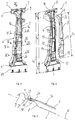
- FIGS. 1 to 6 a vehicle pillar of a vehicle body in the form of a B pillar 1 according to a first embodiment of the present invention is shown.
- the B pillar has an elongated, hollow basic structure and, when installed, by integrating the B pillar 1 as a load-bearing structural element in the motor vehicle body, connects a roof area with a sill area.
- the B-pillar 1 has two supporting structural elements, namely a sheet metal part 2 and a fiber composite part 3.
- the fiber composite part 3 is cup-shaped and placed from the outside on an outer side 4 of the cup-shaped sheet metal part 2.
- the outer side 4 is remote in the installed state of the B-pillar 1 from a passenger compartment, not shown.
- the fiber composite part 3 is disposed on the pressure side of the B pillar 1, so that the fiber composite part 3 is pressed in a side impact against the underlying sheet metal part 2.
- the sheet metal part 2 from top to bottom, a head portion 5, a central portion 6 and a foot portion 7, wherein the central portion 6 defines a longitudinal direction X of the B-pillar 1.
- the sheet metal part 2 may for example have a length of about 1.30 to 1.50 m.
- the length L 5 of the head portion 5 here is less than 15% of the length L 2 of the sheet metal part 2 and about 12% of the length L 2 of the sheet metal part 2 corresponds.
- the length L 7 of the foot portion 7 is here less than 25% of the length L 2 of the sheet metal part 2 and corresponds to about 18% of the length L 2 of the sheet metal part 2.
- the length L 6 of the central portion 6 is thus about 70% of the length L 2 of Sheet metal part 2.
- the head portion 5 connects in the installed state, the roof area, in particular a roof rail with the B-pillar 1, wherein at one, the passenger compartment facing, inner side 8 of the sheet metal part 2, an upper connection region 9 is formed.
- the upper connection region 9 is designed in the manner of a flange with a roughly U-shaped profile in cross-section, in order to engage around the roof rail from the outside in the installed state.
- the sheet metal part 3 on the outer side 4 of the head portion 5 on a support portion 10 via which the fiber composite part 3 can be supported on the roof area, in particular the roof spar.
- the support region 10 is wedge-shaped and widens upwards starting from a lower, tapered section.
- the central portion 6 of the sheet metal part 2 connects.
- the sheet metal part 2 has a hat profile in such a way that on the inside 8 a cavity 11 for receiving vehicle attachment parts not shown in detail, such as a receptacle or a connection point for a closing wedge for the front door, a door lock, a door hinge, a rear door lock, a belt reel or a belt tensioner is formed.
- the sheet metal part 2 has a plurality of passage openings 12 for fixing the vehicle attachment parts.
- Central section 6 large recesses 14 introduced to selectively reduce the weight of the sheet metal part 2.
- Large area recesses 14 are understood to mean that the total area of the recesses 14 extends over at least 10%, preferably between 20% and 80%, in particular between 25% to 50%, of the area of the middle leg 13 of the sheet metal part 2.
- the foot portion 7 of the sheet metal part 2 connects, which serves to connect the B-pillar 1 to the sill area.
- the foot section 7 has a cross-sectionally approximately U-shaped lower connection region 15, which surrounds the sill region from the outside in the installed state.
- the sheet metal part 2 is here a hot-formed and at least partially cured molding, which may for example be made of a 22MnB5 steel sheet and provided with an aluminum-silicon coating.
- the sheet metal part 2 has different sheet thicknesses in the longitudinal direction X, wherein the sheet thickness can be adjusted according to the customer-specific demanded crash zones.
- the fiber composite part 3 covers most of the central portion 6 of the sheet metal part 2.
- the length L 3 of the fiber composite part 3 between 50% and 90%, here about 75% of the length L 2 of the sheet metal part 2 is.
- the fiber composite part 3 extends over the central portion 6 and the head portion 5 of the sheet metal part.
- a lower portion 19 of the fiber composite part 3 ends within the central portion 6.
- the fiber composite part 3 and the foot portion 7 of the sheet metal part 2 axially spaced, that is, the fiber composite part 3 does not overlap the foot portion 7 of the sheet metal part 2, so that the transition of the B Pillar 1 to the threshold range is determined only by the material properties of the sheet metal part 2 in the foot section 7.
- the lower portion 19 of the fiber composite part 3 is formed in cross section straight and in plan view as a semicircle.
- the lower portion 19 of the fiber composite part 3 is positively applied to the lower central portion 6 of the sheet metal part 2 and supported in the longitudinal direction X.
- the sheet metal part 2 in the lower central portion 6 a hardened high-strength portion 20.
- the fiber composite part 3 with the sheet metal part 2 by means of in FIG. 4 shown rivet 22 connected.
- the starting from the lower portion 19 of the fiber composite part 3 in the longitudinal direction X upwardly extending central portion 21 has a U-shaped profile, so that the fiber composite part 3, the hat profile of the sheet metal part 2 in the central portion 6 laterally surrounds, or partially overlaps.
- the sheet-metal shaped part 2 in the central portion 6 has two mutually opposite side walls 23, which adjoin the respective joining flange 16 radially inwardly.
- the side walls 23 have here, for example, in each case an outer shoulder 24, on which the fiber composite part 3 is seated.
- fastening means 25 which are designed for attaching to the B pillar 1 held vehicle attachment parts.
- the fiber composite part 3 is supported in an upper portion 26 at the head portion 5 of the sheet metal part 2 from.
- the fiber composite part 3 in the upper portion 26 has an upwardly widened trained attachment portion 27 which engages around the support portion 10 of the sheet metal part 2 side and is supported against this in the longitudinal direction X of the B-pillar 1.
- the fiber composite part 3 is connected in the contact region 27 by means of connecting means, for example rivets 28 with the support portion 10 of the sheet metal part 2.
- the upper portion 26 of the fiber composite part 3 is also at an angle ⁇ of about 10 ° slightly inward, that is, in the direction of the passenger compartment, is employed.
- the upper end of the fiber composite part 3 is spaced to form a gap 29 from the outside 4 of the sheet metal part 2 in the region of the flange-shaped upper connection region 9.
- the fiber composite part 3 is supported in the contact area 27 via the support portion 10 of the sheet metal part 2 on the roof spar.
- the lower portion 19 is positively applied to the sheet metal part 2, so that the fiber composite part 3 is supported over the central portion 6 of the sheet metal part 2 in the longitudinal direction X.
- the fiber composite part 3 can be adhesively bonded to the sheet-metal shaped part 2 in the middle section 21 and / or in the upper section 26 and / or in the lower section 19. Riveting, nail and / or screw connection technology be connected.
- the fiber composite part 3 may comprise carbon, glass or basalt fibers or metallic fibers.
- the fibers of the fiber composite material can be bound in a resin matrix, in particular an epoxy matrix.
- the fiber components can also be composed as desired from a combination of the aforementioned fiber possibilities. Due to the axial or multiaxial orientation of the fibers, it is also possible to adapt the fiber composite part 3 to the respective fields of application and the required crash properties.
- the fiber composite part 3 can also be adapted by locally different wall thicknesses by the number of fiber layers is varied. In this way, the crash behavior of the B-pillar can be trimmed or varied in sections.
- a barrier layer or decoupling layer 30, between the two structural elements 2, 3, for example, from an adhesive be provided.
- the fiber composite part 2 By incorporating the fiber composite part 2 as a supporting structural element on the pressure side of the B-pillar 1, the fiber composite part 2 can set up in a side impact, respectively upright.
- the middle section 21 In order to adjust the bending behavior of the fiber composite part 2, in short also called “flex", especially the middle section 21 can be trimmed by varying the shape, the wall thickness and the strength to the required target behavior.
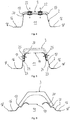
- FIG. 6 For this purpose, an embodiment is shown, wherein alternative embodiments in the FIGS. 7, 8 and 12 are shown, which will be explained in more detail in connection with the following embodiments.
- FIG. 7 is an alternative embodiment of the B-pillar 1 in cross-sectional view along in FIG. 1 shown section line VI-VI shown.
- the fiber composite part 3 can have regions of different wall thicknesses.
- u-profile-shaped fiber composite part 3 has an outer wall 31 and two side walls 32 protruding therefrom.
- the spring behavior of the B-pillar 1 can be trimmed in a force acting on the outside of the B-pillar 1 force.
- the crash behavior of the B-pillar 1 can be changed, in which the outer wall 31 of the fiber composite part 3 is pressed in the direction of the underlying sheet metal part 2, wherein the side walls 32 of the outer wall 31 can yield by relative to the sheet metal part 2 in the direction of arrows 34 set up.
- the material weakening can be designed, for example, by applying a small number of laminate layers in comparison to the adjacent sections of the fiber composite part 3.
- the spring behavior of the B-pillar 1 can also be adjusted by varying the angle of attack ⁇ of the side walls 32 relative to the sheet-metal shaped part 2.
- FIG. 7 With view on FIG. 7 is shown on the left side of the figure, the possibility of varying the spring behavior of the B-pillar 1 by changing the angle of attack ⁇ , whereas on the right side of the figure, the spring behavior by providing the material taper 33 is shown. Only to juxtapose the two possibilities, these are shown in a figure. In principle, both variants can be combined with one another or used separately from one another, wherein these variants can in principle also be formed on both transitions.
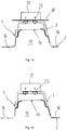
- FIG. 8 is a further alternative embodiment of the B-pillar 1 in cross-sectional view along in FIG. 1 shown section line VI-VI shown.
- a metallic insert 35 is integrated into the matrix system of the fiber composite part 3.
- the reinforcing insert 35 may be made of a cold or hot formed high or ultra high strength steel, depending on the customer's requirement for crash performance.
- the reinforcing insert 35 can have a variable wall thickness in the longitudinal direction X.
- the reinforcement insert 35 here may have an approximately U-shaped, respectively plate-shaped profile.
- the reinforcing insert 35 can also be designed to be narrower, in particular strip-shaped, or significantly wider, so that the reinforcing insert 35 can extend significantly deeper into the side walls 32.
- the reinforcing insert 35 can be integrated into the laying structure of the surrounding fiber materials of the fiber composite part 3 by interweaving fiber strands of the fiber composite part 3 in a form-fitting, respectively supporting manner.
- the reinforcing insert 35 due to its surface texture, respectively roughness and / or a coordinated surface coating concept to be integrated into a matrix surrounding the fibers of the fiber composite material sustainable.
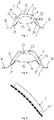
- FIGS. 10 to 12 a B-pillar 1 according to another embodiment of the present invention is shown.
- This embodiment differs only from the above-described embodiments according to FIGS FIGS. 1 to 9 in that 2 additional metal connecting elements 36 are provided for connecting the fiber composite part 3 with the sheet metal part.
- 2 additional metal connecting elements 36 are provided for connecting the fiber composite part 3 with the sheet metal part.
- FIG. 10 is the B-pillar 1 in cross section along in FIG. 1 shown section line III-III shown.
- a metallic connecting element 36 is integrated in the fiber matrix structure of the fiber composite part 3.
- the connecting element 36 is partially integrated in the fiber composite of the fiber composite part 3 and protrudes with free end portions 37 of the fiber composite.
- the fiber composite part 3 is materially connected to the sheet metal part 2, in particular welded.
- the connecting element 36 may have a plurality of narrow, web-like feet, each having a free end portion 37 or a transversely extending flange.
- the connecting elements 36 may be provided to connect the fiber composite part 3 with the sheet metal part 2 at several points.
- the spot or laser welding method is suitable as the welding method.
- the connecting element 36 may be bent to, as in FIG. 10 shown to follow the outer contour of the flange-like upper connection region 9.
- FIGS. 11 and 12 are further cross sections of in FIG. 10 shown B-pillar 1 shown, namely in the FIG. 11 along the in FIG. 1 shown section line XI-XI and in FIG. 12 along the in FIG. 1 shown section line VI-VI.
- the fiber composite part 3 can also be connected to the sheet metal shaped part 2 in these areas by means of the connecting elements 36.
- the in the FIGS. 10 to 12 Sections shown are exemplary of the fact that the fiber composite part 3 over the entire length of continuous or interrupted connected by means of the connecting elements 36 with the sheet metal part 2, in particular can be welded.
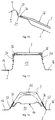
- FIG. 13 is a motor vehicle body according to a first embodiment of the present invention with in the FIGS. 1 to 6 shown and described B-pillar 1 shown.
- a vehicle outer skin 38 in the installed state, can lie flat on the fiber composite part 3.
- the vehicle outer skin 38 can be connected to the fiber composite part 3 of the B pillar by means of the fastening means 25, which are used for attaching the vehicle attachment parts, such as a front door closing wedge 39, a door lock, a door hinge or a rear door arrester 1 connected.
- the vehicle outer skin 38 may be connected in a manner not shown with the joining flanges 16 of the sheet metal part 2.
- FIG. 14 is a motor vehicle body according to a second embodiment of the present invention with in the FIGS. 1 to 6 shown and described B-pillar 1 shown.
- the B-pillar 1 in the embodiment according to the FIG. 14 not covered by a vehicle skin 38.
- the fiber composite part 3 is always visible even in the installed state of the B-pillar 1.
- a driver of the motor vehicle, respectively the passenger, will thus visually perceive when opening a vehicle door that the supporting structural element of the B pillar 1 in the form of the fiber composite part 3 is made of a fiber-reinforced plastic material.
Landscapes
- Engineering & Computer Science (AREA)
- Chemical & Material Sciences (AREA)
- Combustion & Propulsion (AREA)
- Transportation (AREA)
- Mechanical Engineering (AREA)
- Architecture (AREA)
- Structural Engineering (AREA)
- Body Structure For Vehicles (AREA)
Applications Claiming Priority (1)
| Application Number | Priority Date | Filing Date | Title |
|---|---|---|---|
| DE102016116787.8A DE102016116787B3 (de) | 2016-09-07 | 2016-09-07 | B-Säule für eine Kraftfahrzeugkarosserie sowie Kraftfahrzeugkarosserie mit einer solchen B-Säule |
Publications (3)
| Publication Number | Publication Date |
|---|---|
| EP3293095A2 true EP3293095A2 (fr) | 2018-03-14 |
| EP3293095A3 EP3293095A3 (fr) | 2018-03-21 |
| EP3293095B1 EP3293095B1 (fr) | 2020-09-30 |
Family
ID=59686801
Family Applications (1)
| Application Number | Title | Priority Date | Filing Date |
|---|---|---|---|
| EP17187292.2A Active EP3293095B1 (fr) | 2016-09-07 | 2017-08-22 | Pied milieu de carrosserie de véhicule ainsi que carrosserie de véhicule pourvue d'un tel pied milieu |
Country Status (8)
| Country | Link |
|---|---|
| US (1) | US10351177B2 (fr) |
| EP (1) | EP3293095B1 (fr) |
| JP (1) | JP6902971B2 (fr) |
| KR (1) | KR20180028029A (fr) |
| CN (1) | CN107792194B (fr) |
| CA (1) | CA2977875C (fr) |
| DE (1) | DE102016116787B3 (fr) |
| MX (1) | MX2017011458A (fr) |
Cited By (2)
| Publication number | Priority date | Publication date | Assignee | Title |
|---|---|---|---|---|
| DE102021122509A1 (de) | 2021-08-31 | 2023-03-02 | Dr. Ing. H.C. F. Porsche Aktiengesellschaft | Kraftfahrzeugstrukturbauteil mit einem metallischen Profil-Grundkörper und einem damit verbundenen faserverstärkten Verstärkungselement aus Kunststoff sowie Verfahren zur Herstellung eines solchen Kraftfahrzeugstrukturbauteils |
| WO2024227482A1 (fr) * | 2023-05-02 | 2024-11-07 | Bayerische Motoren Werke Aktiengesellschaft | Structure de carrosserie pour véhicule automobile |
Families Citing this family (20)
| Publication number | Priority date | Publication date | Assignee | Title |
|---|---|---|---|---|
| CN106853846B (zh) * | 2015-12-09 | 2022-02-01 | 福特全球技术公司 | 车身部件 |
| JP6555303B2 (ja) * | 2017-07-28 | 2019-08-07 | マツダ株式会社 | 車両の側部車体構造 |
| JP6898169B2 (ja) * | 2017-08-02 | 2021-07-07 | トヨタ自動車株式会社 | ボディ骨格構造 |
| DE102017220228A1 (de) * | 2017-11-14 | 2019-05-16 | Bayerische Motoren Werke Aktiengesellschaft | Verfahren zur Herstellung eines Hybridbauteils aus pressgehärtetem Blech und faserverstärktem Kunststoff, sowie hiermit hergestelltes Hybridbauteil |
| DE102018113141A1 (de) * | 2018-06-01 | 2019-12-05 | Muhr Und Bender Kg | B-Säule für eine Kraftfahrzeugkarosserie sowie Kraftfahrzeugkarosserie mit einer solchen B-Säule |
| CN108791504A (zh) * | 2018-06-13 | 2018-11-13 | 芜湖恒信汽车内饰制造有限公司 | 一种车身结构及具有该结构的车身b柱和车身c柱 |
| DE102018215364B4 (de) * | 2018-09-11 | 2022-12-22 | Volkswagen Aktiengesellschaft | Karosseriestruktur für ein Fahrzeug |
| SE1950545A1 (en) | 2019-05-07 | 2020-11-08 | Gestamp Hardtech Ab | Corner patch |
| US10780820B1 (en) * | 2019-05-23 | 2020-09-22 | Inview Vehicle Trim Corp. | Vehicle door pillar light assembly and method of use thereof |
| JP7366652B2 (ja) * | 2019-09-06 | 2023-10-23 | 日産自動車株式会社 | T字形複合構造部材 |
| US11897544B2 (en) * | 2019-09-11 | 2024-02-13 | Nippon Steel Corporation | Center pillar inner and center pillar |
| CN112537371A (zh) * | 2019-09-20 | 2021-03-23 | 北京宝沃汽车有限公司 | B柱内板以及具有其的车辆 |
| DE102020110241B4 (de) | 2020-04-15 | 2023-02-02 | Thyssenkrupp Steel Europe Ag | Karosseriesäule, insbesondere A-Säule, für ein Kraftfahrzeug |
| JP7715739B2 (ja) | 2020-07-17 | 2025-07-30 | オートテック・エンジニアリング・ソシエダッド・リミターダ | 延性の高いパッチを有する金属構造部品およびその製造方法 |
| KR20220055949A (ko) * | 2020-10-27 | 2022-05-04 | 현대자동차주식회사 | 차체 조인트 구조 |
| KR20220075120A (ko) | 2020-11-27 | 2022-06-07 | 서진산업 주식회사 | 강성증대를 위한 엠보싱 무늬 적용 비필라 |
| KR102817550B1 (ko) * | 2021-01-12 | 2025-06-05 | 현대자동차주식회사 | 차량용 사이드 아우터 패널의 도어 힌지 마운팅부 |
| DE102021114467A1 (de) | 2021-06-05 | 2022-12-08 | Ford Global Technologies Llc | Karosseriesäule, insbesondere B-Säule, eines Kraftfahrzeugs mit geneigten Festigkeitsübergangsbereichen |
| DE102021209563A1 (de) | 2021-08-31 | 2023-03-02 | Volkswagen Aktiengesellschaft | Kraftfahrzeugstrukturbauteil mit einem metallischen Profil-Grundkörper und einem damit verbundenen faserverstärkten Verstärkungselement aus Kunststoff sowie Verfahren zum Verbinden eines metallischen Profil-Grundkörpers mit einem faserverstärkten Verstärkungselement aus Kunststoff |
| KR102639712B1 (ko) | 2021-12-30 | 2024-02-21 | 현대자동차주식회사 | 모빌리티의 바디 |
Family Cites Families (15)
| Publication number | Priority date | Publication date | Assignee | Title |
|---|---|---|---|---|
| US6296301B1 (en) * | 1999-12-21 | 2001-10-02 | Daimlerchrysler Corporation | Motor vehicle body structure using a woven fiber |
| JP4196746B2 (ja) * | 2003-06-17 | 2008-12-17 | 日産自動車株式会社 | 自動車のセンターピラー構造 |
| DE102006027546A1 (de) * | 2006-06-14 | 2007-12-20 | Volkswagen Ag | Aufprallschutzverstärkungsteil |
| DE102007053353B4 (de) * | 2007-10-30 | 2017-06-08 | Deutsches Zentrum für Luft- und Raumfahrt e.V. | Karosseriesäule für Fahrzeuge und Fahrzeugkarosserie |
| US8047603B2 (en) * | 2008-06-13 | 2011-11-01 | Sabic Innovative Plastics Ip B.V. | Plastic crush countermeasure for vehicles |
| DE102008032344B4 (de) * | 2008-07-09 | 2021-01-21 | Bayerische Motoren Werke Aktiengesellschaft | Baugruppe, insbes. für eine Fahrzeugkarosserie |
| DE102009005763A1 (de) * | 2009-01-23 | 2010-07-29 | Lanxess Deutschland Gmbh | Rahmenseitenteil einer Kraftfahrzeug Karosserie |
| KR20140043318A (ko) * | 2011-02-03 | 2014-04-09 | 데이진 가부시키가이샤 | 차량 골격부재 |
| DE102011054909A1 (de) * | 2011-10-28 | 2013-05-02 | Benteler Automobiltechnik Gmbh | Verfahren zur Herstellung eines Kraftfahrzeugbauteils sowie nach dem Verfahren hergestelltes Kraftfahrzeugbauteil |
| DE102011120519A1 (de) * | 2011-12-08 | 2013-06-13 | GM Global Technology Operations LLC (n. d. Gesetzen des Staates Delaware) | Verstärkung für eine Fahrzeugsäule, insbesodnere die B-Säule eines Fahrzeuges |
| DE102012023653A1 (de) * | 2012-11-28 | 2014-05-28 | GM Global Technology Operations LLC (n. d. Gesetzen des Staates Delaware) | Kraftfahrzeugkarosserie mit Leichtbauteil |
| DE102013108265B4 (de) * | 2013-08-01 | 2018-09-13 | Thyssen Krupp Steel Europe AG | Baugruppe von gehärteten Bauteilen und Verfahren zur Herstellung |
| DE102014003378A1 (de) * | 2014-03-05 | 2015-09-10 | Daimler Ag | Fahrzeugsäule für eine Karosserie eines Personenkraftwagens |
| JP6049146B2 (ja) * | 2014-09-24 | 2016-12-21 | 富士重工業株式会社 | 車体骨格構造 |
| FR3030356B1 (fr) * | 2014-12-23 | 2019-04-05 | Renault S.A.S | Procede de fabrication d'une piece de structure hybride de vehicule automobile et piece de structure hybride correspondante. |
-
2016
- 2016-09-07 DE DE102016116787.8A patent/DE102016116787B3/de not_active Expired - Fee Related
-
2017
- 2017-08-22 EP EP17187292.2A patent/EP3293095B1/fr active Active
- 2017-08-24 US US15/684,966 patent/US10351177B2/en active Active
- 2017-08-31 CA CA2977875A patent/CA2977875C/fr not_active Expired - Fee Related
- 2017-09-04 KR KR1020170112481A patent/KR20180028029A/ko not_active Withdrawn
- 2017-09-05 CN CN201710790634.5A patent/CN107792194B/zh active Active
- 2017-09-06 MX MX2017011458A patent/MX2017011458A/es unknown
- 2017-09-07 JP JP2017172092A patent/JP6902971B2/ja active Active
Cited By (2)
| Publication number | Priority date | Publication date | Assignee | Title |
|---|---|---|---|---|
| DE102021122509A1 (de) | 2021-08-31 | 2023-03-02 | Dr. Ing. H.C. F. Porsche Aktiengesellschaft | Kraftfahrzeugstrukturbauteil mit einem metallischen Profil-Grundkörper und einem damit verbundenen faserverstärkten Verstärkungselement aus Kunststoff sowie Verfahren zur Herstellung eines solchen Kraftfahrzeugstrukturbauteils |
| WO2024227482A1 (fr) * | 2023-05-02 | 2024-11-07 | Bayerische Motoren Werke Aktiengesellschaft | Structure de carrosserie pour véhicule automobile |
Also Published As
| Publication number | Publication date |
|---|---|
| JP6902971B2 (ja) | 2021-07-14 |
| EP3293095B1 (fr) | 2020-09-30 |
| US10351177B2 (en) | 2019-07-16 |
| EP3293095A3 (fr) | 2018-03-21 |
| CN107792194B (zh) | 2021-10-29 |
| DE102016116787B3 (de) | 2017-10-05 |
| JP2018039501A (ja) | 2018-03-15 |
| CN107792194A (zh) | 2018-03-13 |
| CA2977875A1 (fr) | 2018-03-07 |
| CA2977875C (fr) | 2019-11-12 |
| KR20180028029A (ko) | 2018-03-15 |
| MX2017011458A (es) | 2018-09-21 |
| US20180065681A1 (en) | 2018-03-08 |
Similar Documents
| Publication | Publication Date | Title |
|---|---|---|
| DE102016116787B3 (de) | B-Säule für eine Kraftfahrzeugkarosserie sowie Kraftfahrzeugkarosserie mit einer solchen B-Säule | |
| EP3150466B1 (fr) | Colonne b pour carrosserie de vehicule et son procede de production | |
| EP2976250B1 (fr) | Seuil de porte pour une carrosserie de véhicule | |
| EP1912849B1 (fr) | Tole de renforcement conçue pour une colonne b d'une carrosserie de vehicule | |
| DE102011120519A1 (de) | Verstärkung für eine Fahrzeugsäule, insbesodnere die B-Säule eines Fahrzeuges | |
| DE102013015420B4 (de) | Stoßfängersystem und Verfahren für die Herstellung eines Stoßfängersystems | |
| EP2711209B1 (fr) | Agencement de support pour un attelage ou un support de charge doté d'une platine de tôle | |
| WO2012007346A1 (fr) | Renfort de pied milieu d'un véhicule automobile | |
| DE102009042272A1 (de) | Leichtbauteil | |
| DE102008017055A1 (de) | Querträger für einen Stoßfänger eines Fahrzeugs und Verfahren zum Herstellen eines Querträgers | |
| EP3519278B1 (fr) | Élément structural pour une carrosserie de véhicule automobile | |
| DE102009047951A1 (de) | Säule für einen Kraftwagen | |
| WO2014040832A1 (fr) | Carrosserie de véhicule automobile comprenant une paroi latérale et son procédé de fabrication | |
| EP3461659B1 (fr) | Dispositif de support pour une barre d'attelage doté d'un élément de support trempé à la presse | |
| EP2867096A1 (fr) | Élément de support et élément d'absorption d'énergie à construction hybride pour un véhicule automobile | |
| DE102013001668A1 (de) | Karosseriestruktur eines Kraftfahrzeugs und Kraftfahrzeug mit einer derartigen Karosseriestruktur | |
| EP3575189B1 (fr) | Pied milieu pour une carrosserie de véhicule ainsi que carrosserie de véhicule pourvue d'un tel pied milieu | |
| EP3415349B1 (fr) | Dispositif de support pour une barre d'attelage et étrier de guidage dotés d'un élément de support multicomposant | |
| EP1880924B1 (fr) | Poutre en tant que traverse ou longeron dans un véhicule automobile | |
| DE102008010720A1 (de) | Aufprallträger für ein Fahrzeug | |
| DE102015012262B4 (de) | Tür für einen Kraftwagen | |
| EP3010740A1 (fr) | Élément de renforcement de portière de véhicule automobile, portière de véhicule automobile et procédé de fabrication d'un élément de renforcement | |
| EP3427979B1 (fr) | Dispositif de support pour une barre d'attelage et étrier de guidage dotés d'un élément de support de forme étalon | |
| EP2711208B1 (fr) | Agencement de support pour un attelage ou un support de charge doté d'un élément en matériau fibreux | |
| DE102011052291B4 (de) | Kraftfahrzeugbauteil sowie Verfahren zur Herstellung eines Kraftfahrzeugbauteils |
Legal Events
| Date | Code | Title | Description |
|---|---|---|---|
| PUAI | Public reference made under article 153(3) epc to a published international application that has entered the european phase |
Free format text: ORIGINAL CODE: 0009012 |
|
| STAA | Information on the status of an ep patent application or granted ep patent |
Free format text: STATUS: THE APPLICATION HAS BEEN PUBLISHED |
|
| PUAL | Search report despatched |
Free format text: ORIGINAL CODE: 0009013 |
|
| AK | Designated contracting states |
Kind code of ref document: A2 Designated state(s): AL AT BE BG CH CY CZ DE DK EE ES FI FR GB GR HR HU IE IS IT LI LT LU LV MC MK MT NL NO PL PT RO RS SE SI SK SM TR |
|
| AX | Request for extension of the european patent |
Extension state: BA ME |
|
| AK | Designated contracting states |
Kind code of ref document: A3 Designated state(s): AL AT BE BG CH CY CZ DE DK EE ES FI FR GB GR HR HU IE IS IT LI LT LU LV MC MK MT NL NO PL PT RO RS SE SI SK SM TR |
|
| AX | Request for extension of the european patent |
Extension state: BA ME |
|
| RIC1 | Information provided on ipc code assigned before grant |
Ipc: B62D 25/04 20060101ALI20180210BHEP Ipc: B62D 29/00 20060101AFI20180210BHEP |
|
| STAA | Information on the status of an ep patent application or granted ep patent |
Free format text: STATUS: REQUEST FOR EXAMINATION WAS MADE |
|
| 17P | Request for examination filed |
Effective date: 20180504 |
|
| RBV | Designated contracting states (corrected) |
Designated state(s): AL AT BE BG CH CY CZ DE DK EE ES FI FR GB GR HR HU IE IS IT LI LT LU LV MC MK MT NL NO PL PT RO RS SE SI SK SM TR |
|
| STAA | Information on the status of an ep patent application or granted ep patent |
Free format text: STATUS: EXAMINATION IS IN PROGRESS |
|
| 17Q | First examination report despatched |
Effective date: 20190102 |
|
| GRAP | Despatch of communication of intention to grant a patent |
Free format text: ORIGINAL CODE: EPIDOSNIGR1 |
|
| STAA | Information on the status of an ep patent application or granted ep patent |
Free format text: STATUS: GRANT OF PATENT IS INTENDED |
|
| INTG | Intention to grant announced |
Effective date: 20200422 |
|
| GRAS | Grant fee paid |
Free format text: ORIGINAL CODE: EPIDOSNIGR3 |
|
| GRAA | (expected) grant |
Free format text: ORIGINAL CODE: 0009210 |
|
| STAA | Information on the status of an ep patent application or granted ep patent |
Free format text: STATUS: THE PATENT HAS BEEN GRANTED |
|
| AK | Designated contracting states |
Kind code of ref document: B1 Designated state(s): AL AT BE BG CH CY CZ DE DK EE ES FI FR GB GR HR HU IE IS IT LI LT LU LV MC MK MT NL NO PL PT RO RS SE SI SK SM TR |
|
| REG | Reference to a national code |
Ref country code: CH Ref legal event code: EP Ref country code: GB Ref legal event code: FG4D Free format text: NOT ENGLISH |
|
| REG | Reference to a national code |
Ref country code: AT Ref legal event code: REF Ref document number: 1318524 Country of ref document: AT Kind code of ref document: T Effective date: 20201015 |
|
| REG | Reference to a national code |
Ref country code: IE Ref legal event code: FG4D Free format text: LANGUAGE OF EP DOCUMENT: GERMAN |
|
| REG | Reference to a national code |
Ref country code: DE Ref legal event code: R096 Ref document number: 502017007493 Country of ref document: DE |
|
| PG25 | Lapsed in a contracting state [announced via postgrant information from national office to epo] |
Ref country code: NO Free format text: LAPSE BECAUSE OF FAILURE TO SUBMIT A TRANSLATION OF THE DESCRIPTION OR TO PAY THE FEE WITHIN THE PRESCRIBED TIME-LIMIT Effective date: 20201230 Ref country code: GR Free format text: LAPSE BECAUSE OF FAILURE TO SUBMIT A TRANSLATION OF THE DESCRIPTION OR TO PAY THE FEE WITHIN THE PRESCRIBED TIME-LIMIT Effective date: 20201231 Ref country code: BG Free format text: LAPSE BECAUSE OF FAILURE TO SUBMIT A TRANSLATION OF THE DESCRIPTION OR TO PAY THE FEE WITHIN THE PRESCRIBED TIME-LIMIT Effective date: 20201230 Ref country code: SE Free format text: LAPSE BECAUSE OF FAILURE TO SUBMIT A TRANSLATION OF THE DESCRIPTION OR TO PAY THE FEE WITHIN THE PRESCRIBED TIME-LIMIT Effective date: 20200930 Ref country code: FI Free format text: LAPSE BECAUSE OF FAILURE TO SUBMIT A TRANSLATION OF THE DESCRIPTION OR TO PAY THE FEE WITHIN THE PRESCRIBED TIME-LIMIT Effective date: 20200930 Ref country code: HR Free format text: LAPSE BECAUSE OF FAILURE TO SUBMIT A TRANSLATION OF THE DESCRIPTION OR TO PAY THE FEE WITHIN THE PRESCRIBED TIME-LIMIT Effective date: 20200930 |
|
| PG25 | Lapsed in a contracting state [announced via postgrant information from national office to epo] |
Ref country code: LV Free format text: LAPSE BECAUSE OF FAILURE TO SUBMIT A TRANSLATION OF THE DESCRIPTION OR TO PAY THE FEE WITHIN THE PRESCRIBED TIME-LIMIT Effective date: 20200930 Ref country code: RS Free format text: LAPSE BECAUSE OF FAILURE TO SUBMIT A TRANSLATION OF THE DESCRIPTION OR TO PAY THE FEE WITHIN THE PRESCRIBED TIME-LIMIT Effective date: 20200930 |
|
| REG | Reference to a national code |
Ref country code: NL Ref legal event code: MP Effective date: 20200930 |
|
| REG | Reference to a national code |
Ref country code: LT Ref legal event code: MG4D |
|
| PG25 | Lapsed in a contracting state [announced via postgrant information from national office to epo] |
Ref country code: CZ Free format text: LAPSE BECAUSE OF FAILURE TO SUBMIT A TRANSLATION OF THE DESCRIPTION OR TO PAY THE FEE WITHIN THE PRESCRIBED TIME-LIMIT Effective date: 20200930 Ref country code: RO Free format text: LAPSE BECAUSE OF FAILURE TO SUBMIT A TRANSLATION OF THE DESCRIPTION OR TO PAY THE FEE WITHIN THE PRESCRIBED TIME-LIMIT Effective date: 20200930 Ref country code: PT Free format text: LAPSE BECAUSE OF FAILURE TO SUBMIT A TRANSLATION OF THE DESCRIPTION OR TO PAY THE FEE WITHIN THE PRESCRIBED TIME-LIMIT Effective date: 20210201 Ref country code: LT Free format text: LAPSE BECAUSE OF FAILURE TO SUBMIT A TRANSLATION OF THE DESCRIPTION OR TO PAY THE FEE WITHIN THE PRESCRIBED TIME-LIMIT Effective date: 20200930 Ref country code: NL Free format text: LAPSE BECAUSE OF FAILURE TO SUBMIT A TRANSLATION OF THE DESCRIPTION OR TO PAY THE FEE WITHIN THE PRESCRIBED TIME-LIMIT Effective date: 20200930 Ref country code: EE Free format text: LAPSE BECAUSE OF FAILURE TO SUBMIT A TRANSLATION OF THE DESCRIPTION OR TO PAY THE FEE WITHIN THE PRESCRIBED TIME-LIMIT Effective date: 20200930 Ref country code: SM Free format text: LAPSE BECAUSE OF FAILURE TO SUBMIT A TRANSLATION OF THE DESCRIPTION OR TO PAY THE FEE WITHIN THE PRESCRIBED TIME-LIMIT Effective date: 20200930 |
|
| PG25 | Lapsed in a contracting state [announced via postgrant information from national office to epo] |
Ref country code: ES Free format text: LAPSE BECAUSE OF FAILURE TO SUBMIT A TRANSLATION OF THE DESCRIPTION OR TO PAY THE FEE WITHIN THE PRESCRIBED TIME-LIMIT Effective date: 20200930 Ref country code: AL Free format text: LAPSE BECAUSE OF FAILURE TO SUBMIT A TRANSLATION OF THE DESCRIPTION OR TO PAY THE FEE WITHIN THE PRESCRIBED TIME-LIMIT Effective date: 20200930 Ref country code: PL Free format text: LAPSE BECAUSE OF FAILURE TO SUBMIT A TRANSLATION OF THE DESCRIPTION OR TO PAY THE FEE WITHIN THE PRESCRIBED TIME-LIMIT Effective date: 20200930 Ref country code: IS Free format text: LAPSE BECAUSE OF FAILURE TO SUBMIT A TRANSLATION OF THE DESCRIPTION OR TO PAY THE FEE WITHIN THE PRESCRIBED TIME-LIMIT Effective date: 20210130 |
|
| PG25 | Lapsed in a contracting state [announced via postgrant information from national office to epo] |
Ref country code: SK Free format text: LAPSE BECAUSE OF FAILURE TO SUBMIT A TRANSLATION OF THE DESCRIPTION OR TO PAY THE FEE WITHIN THE PRESCRIBED TIME-LIMIT Effective date: 20200930 |
|
| REG | Reference to a national code |
Ref country code: DE Ref legal event code: R097 Ref document number: 502017007493 Country of ref document: DE |
|
| PLBE | No opposition filed within time limit |
Free format text: ORIGINAL CODE: 0009261 |
|
| STAA | Information on the status of an ep patent application or granted ep patent |
Free format text: STATUS: NO OPPOSITION FILED WITHIN TIME LIMIT |
|
| PG25 | Lapsed in a contracting state [announced via postgrant information from national office to epo] |
Ref country code: DK Free format text: LAPSE BECAUSE OF FAILURE TO SUBMIT A TRANSLATION OF THE DESCRIPTION OR TO PAY THE FEE WITHIN THE PRESCRIBED TIME-LIMIT Effective date: 20200930 |
|
| 26N | No opposition filed |
Effective date: 20210701 |
|
| PG25 | Lapsed in a contracting state [announced via postgrant information from national office to epo] |
Ref country code: IT Free format text: LAPSE BECAUSE OF FAILURE TO SUBMIT A TRANSLATION OF THE DESCRIPTION OR TO PAY THE FEE WITHIN THE PRESCRIBED TIME-LIMIT Effective date: 20200930 |
|
| PG25 | Lapsed in a contracting state [announced via postgrant information from national office to epo] |
Ref country code: SI Free format text: LAPSE BECAUSE OF FAILURE TO SUBMIT A TRANSLATION OF THE DESCRIPTION OR TO PAY THE FEE WITHIN THE PRESCRIBED TIME-LIMIT Effective date: 20200930 |
|
| REG | Reference to a national code |
Ref country code: CH Ref legal event code: PL |
|
| PG25 | Lapsed in a contracting state [announced via postgrant information from national office to epo] |
Ref country code: MC Free format text: LAPSE BECAUSE OF FAILURE TO SUBMIT A TRANSLATION OF THE DESCRIPTION OR TO PAY THE FEE WITHIN THE PRESCRIBED TIME-LIMIT Effective date: 20200930 |
|
| REG | Reference to a national code |
Ref country code: BE Ref legal event code: MM Effective date: 20210831 |
|
| PG25 | Lapsed in a contracting state [announced via postgrant information from national office to epo] |
Ref country code: LI Free format text: LAPSE BECAUSE OF NON-PAYMENT OF DUE FEES Effective date: 20210831 Ref country code: CH Free format text: LAPSE BECAUSE OF NON-PAYMENT OF DUE FEES Effective date: 20210831 |
|
| PG25 | Lapsed in a contracting state [announced via postgrant information from national office to epo] |
Ref country code: IS Free format text: LAPSE BECAUSE OF FAILURE TO SUBMIT A TRANSLATION OF THE DESCRIPTION OR TO PAY THE FEE WITHIN THE PRESCRIBED TIME-LIMIT Effective date: 20210130 Ref country code: LU Free format text: LAPSE BECAUSE OF NON-PAYMENT OF DUE FEES Effective date: 20210822 |
|
| PG25 | Lapsed in a contracting state [announced via postgrant information from national office to epo] |
Ref country code: IE Free format text: LAPSE BECAUSE OF NON-PAYMENT OF DUE FEES Effective date: 20210822 Ref country code: BE Free format text: LAPSE BECAUSE OF NON-PAYMENT OF DUE FEES Effective date: 20210831 |
|
| PG25 | Lapsed in a contracting state [announced via postgrant information from national office to epo] |
Ref country code: HU Free format text: LAPSE BECAUSE OF FAILURE TO SUBMIT A TRANSLATION OF THE DESCRIPTION OR TO PAY THE FEE WITHIN THE PRESCRIBED TIME-LIMIT; INVALID AB INITIO Effective date: 20170822 |
|
| PG25 | Lapsed in a contracting state [announced via postgrant information from national office to epo] |
Ref country code: CY Free format text: LAPSE BECAUSE OF FAILURE TO SUBMIT A TRANSLATION OF THE DESCRIPTION OR TO PAY THE FEE WITHIN THE PRESCRIBED TIME-LIMIT Effective date: 20200930 |
|
| REG | Reference to a national code |
Ref country code: AT Ref legal event code: MM01 Ref document number: 1318524 Country of ref document: AT Kind code of ref document: T Effective date: 20220822 |
|
| PG25 | Lapsed in a contracting state [announced via postgrant information from national office to epo] |
Ref country code: AT Free format text: LAPSE BECAUSE OF NON-PAYMENT OF DUE FEES Effective date: 20220822 |
|
| PG25 | Lapsed in a contracting state [announced via postgrant information from national office to epo] |
Ref country code: MK Free format text: LAPSE BECAUSE OF FAILURE TO SUBMIT A TRANSLATION OF THE DESCRIPTION OR TO PAY THE FEE WITHIN THE PRESCRIBED TIME-LIMIT Effective date: 20200930 |
|
| PG25 | Lapsed in a contracting state [announced via postgrant information from national office to epo] |
Ref country code: MT Free format text: LAPSE BECAUSE OF FAILURE TO SUBMIT A TRANSLATION OF THE DESCRIPTION OR TO PAY THE FEE WITHIN THE PRESCRIBED TIME-LIMIT Effective date: 20200930 |
|
| PGFP | Annual fee paid to national office [announced via postgrant information from national office to epo] |
Ref country code: DE Payment date: 20250805 Year of fee payment: 9 |
|
| PGFP | Annual fee paid to national office [announced via postgrant information from national office to epo] |
Ref country code: GB Payment date: 20250821 Year of fee payment: 9 |
|
| PGFP | Annual fee paid to national office [announced via postgrant information from national office to epo] |
Ref country code: FR Payment date: 20250828 Year of fee payment: 9 |
|
| PG25 | Lapsed in a contracting state [announced via postgrant information from national office to epo] |
Ref country code: TR Free format text: LAPSE BECAUSE OF FAILURE TO SUBMIT A TRANSLATION OF THE DESCRIPTION OR TO PAY THE FEE WITHIN THE PRESCRIBED TIME-LIMIT Effective date: 20200930 |