EP3293371A2 - Système de régulation de température d'une turbomachine - Google Patents
Système de régulation de température d'une turbomachine Download PDFInfo
- Publication number
- EP3293371A2 EP3293371A2 EP17189512.1A EP17189512A EP3293371A2 EP 3293371 A2 EP3293371 A2 EP 3293371A2 EP 17189512 A EP17189512 A EP 17189512A EP 3293371 A2 EP3293371 A2 EP 3293371A2
- Authority
- EP
- European Patent Office
- Prior art keywords
- seal
- steam turbine
- gas
- steam
- seal location
- Prior art date
- Legal status (The legal status is an assumption and is not a legal conclusion. Google has not performed a legal analysis and makes no representation as to the accuracy of the status listed.)
- Granted
Links
Images
Classifications
-
- F—MECHANICAL ENGINEERING; LIGHTING; HEATING; WEAPONS; BLASTING
- F01—MACHINES OR ENGINES IN GENERAL; ENGINE PLANTS IN GENERAL; STEAM ENGINES
- F01K—STEAM ENGINE PLANTS; STEAM ACCUMULATORS; ENGINE PLANTS NOT OTHERWISE PROVIDED FOR; ENGINES USING SPECIAL WORKING FLUIDS OR CYCLES
- F01K13/00—General layout or general methods of operation of complete plants
- F01K13/02—Controlling, e.g. stopping or starting
-
- F—MECHANICAL ENGINEERING; LIGHTING; HEATING; WEAPONS; BLASTING
- F01—MACHINES OR ENGINES IN GENERAL; ENGINE PLANTS IN GENERAL; STEAM ENGINES
- F01D—NON-POSITIVE DISPLACEMENT MACHINES OR ENGINES, e.g. STEAM TURBINES
- F01D11/00—Preventing or minimising internal leakage of working-fluid, e.g. between stages
- F01D11/02—Preventing or minimising internal leakage of working-fluid, e.g. between stages by non-contact sealings, e.g. of labyrinth type
- F01D11/04—Preventing or minimising internal leakage of working-fluid, e.g. between stages by non-contact sealings, e.g. of labyrinth type using sealing fluid, e.g. steam
- F01D11/06—Control thereof
-
- F—MECHANICAL ENGINEERING; LIGHTING; HEATING; WEAPONS; BLASTING
- F01—MACHINES OR ENGINES IN GENERAL; ENGINE PLANTS IN GENERAL; STEAM ENGINES
- F01D—NON-POSITIVE DISPLACEMENT MACHINES OR ENGINES, e.g. STEAM TURBINES
- F01D25/00—Component parts, details, or accessories, not provided for in, or of interest apart from, other groups
- F01D25/08—Cooling; Heating; Heat-insulation
- F01D25/10—Heating, e.g. warming-up before starting
-
- F—MECHANICAL ENGINEERING; LIGHTING; HEATING; WEAPONS; BLASTING
- F05—INDEXING SCHEMES RELATING TO ENGINES OR PUMPS IN VARIOUS SUBCLASSES OF CLASSES F01-F04
- F05D—INDEXING SCHEME FOR ASPECTS RELATING TO NON-POSITIVE-DISPLACEMENT MACHINES OR ENGINES, GAS-TURBINES OR JET-PROPULSION PLANTS
- F05D2220/00—Application
- F05D2220/30—Application in turbines
- F05D2220/31—Application in turbines in steam turbines
-
- F—MECHANICAL ENGINEERING; LIGHTING; HEATING; WEAPONS; BLASTING
- F05—INDEXING SCHEMES RELATING TO ENGINES OR PUMPS IN VARIOUS SUBCLASSES OF CLASSES F01-F04
- F05D—INDEXING SCHEME FOR ASPECTS RELATING TO NON-POSITIVE-DISPLACEMENT MACHINES OR ENGINES, GAS-TURBINES OR JET-PROPULSION PLANTS
- F05D2240/00—Components
- F05D2240/55—Seals
-
- F—MECHANICAL ENGINEERING; LIGHTING; HEATING; WEAPONS; BLASTING
- F05—INDEXING SCHEMES RELATING TO ENGINES OR PUMPS IN VARIOUS SUBCLASSES OF CLASSES F01-F04
- F05D—INDEXING SCHEME FOR ASPECTS RELATING TO NON-POSITIVE-DISPLACEMENT MACHINES OR ENGINES, GAS-TURBINES OR JET-PROPULSION PLANTS
- F05D2260/00—Function
- F05D2260/20—Heat transfer, e.g. cooling
Definitions
- the subject matter disclosed herein relates to power systems. More particularly, the subject matter disclosed herein relates to controlling temperatures and temperature differentials in steam turbine power systems.
- Turbomachines including steam turbine power systems (also referred to as steam turbines or steam turbomachines), are employed in thermal power plants and may also be utilized in a combined-cycle configuration whereby steam is preheated prior to entering the turbine.
- a combined-cycle configuration includes a gas turbine and a heat recovery steam generator (HRSG), which utilizes exhaust from the gas turbine to generate steam for subsequent use in the steam turbine.
- HRSG heat recovery steam generator
- the steam generating components e.g., boiler, gas turbine and HRSG
- the steam generating components are typically run at a sub-design level load so as to provide lower-temperature steam (relative to operating temperature steam) to the steam turbine, thereby limiting the temperature difference (and with it, the thermal expansion stresses) within the turbine components.
- Running higher-temperature steam through the steam turbine at the start-up phase can shorten the usable life of its components or can damage the turbine, e.g., by fracture initialization or plastic deformation.
- operating the steam generator at lower loads can waste fuel due to its lower efficiency, and the corresponding lower efficiency of the steam turbine.
- operating at these lower loads can yield higher emission levels due to less complete combustion.
- Various embodiments of the disclosure include a system having: a first steam turbine coupled with a shaft; a seal system coupled with the shaft, the seal system including a set of linearly disposed seal locations on each side of the steam turbine along the shaft, each seal location corresponding with a control valve for controlling a flow of fluid there through; and a control system coupled with each of the control valves, the control system configured to control flow of a dry air or gas to at least one of the seal locations for heating the system.
- a first aspect of the disclosure includes a system having: a first steam turbine coupled with a shaft; a seal system coupled with the shaft, the seal system including a set of linearly disposed seal locations on each side of the steam turbine along the shaft, each seal location corresponding with a control valve for controlling a flow of fluid therethrough; and a control system coupled with each of the control valves, the control system configured to control flow of a dry air or gas to at least one of the seal locations for heating the system.
- a second aspect of the disclosure includes a system having: a first steam turbine coupled with a shaft; a seal system coupled with the shaft, the seal system including a set of linearly disposed seal locations on each side of the first steam turbine along the shaft, each seal location corresponding with a control valve for controlling a flow of fluid therethrough; and a control system coupled with each of the control valves, the control system configured to permit flow of a dry air or gas to at least one of the seal locations in response to determining the first steam turbine is in a startup mode, wherein the dry air or gas is heated by an external heating system.
- a third aspect of the disclosure includes a system having: a steam turbine coupled with a shaft; a seal system coupled with the shaft, the seal system including a set of linearly disposed seal locations on each side of the steam turbine along the shaft, each seal location corresponding with a control valve for controlling a flow of fluid therethrough; and a control system coupled with each of the control valves, the control system configured to permit flow of a dry air or gas consisting substantially of nitrogen (N 2 ) to at least one of the seal locations in response to determining the steam turbine is in a startup mode, wherein the dry air or gas is heated by at least one of relief steam from the steam turbine or another steam turbine, gland seal steam from the steam turbine or the another steam turbine, or leak-off steam from the steam turbine or the another steam turbine.
- N 2 nitrogen
- the subject matter disclosed herein relates to power systems. More particularly, the subject matter disclosed herein relates to controlling heat differentials in steam turbine power systems.
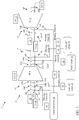
- FIG. 1 is a schematic depiction of a system 2 according to various embodiments.
- system 2 is a steam turbine system, such as a combined-cycle steam turbine system.
- System 2 can include a first steam turbine 4 and a second steam turbine 6, each of which may be coupled to a common, or separate, shaft(s) 8.
- steam turbine(s) 4, 6 can translate thermal energy from steam into rotational energy, via shaft(s) 8, which may be used, e.g., to drive one or more dynamoelectric machines 10 (e.g., generators).
- first steam turbine 4 includes a high pressure or combined high pressure/intermediate pressure steam turbine
- second steam turbine 6 includes an intermediate pressure steam turbine, a combined intermediate pressure/low pressure steam turbine, or a low pressure steam turbine.
- system 2 can further include a seal system 12 coupled with shaft 8, where seal system 12 includes a set of linearly disposed (along shaft 8) seal locations 14 on each side of steam turbine 4. Each seal location 14 can have a corresponding control valve 16 for controlling a flow of fluid therethrough.
- seal system 12 includes a labyrinth seal system, with linearly overlapping seal components forming a seal around shaft 8.
- each seal location is bordered by two adjacent seals, such that three (3) seal locations are formed from four (4) physical seals.
- a control system 18 can be coupled with each of the control valves 16, where control system 18 is configured to control flow of a dry air or gas to at least one of seal locations 14 for pre-heating system 2.
- dry air or gas may have a dew point less than -20 degrees Celsius.
- dry air or gas has an oil content of less than approximately 0.01 milligrams (mg) per cubic meter (m 3 ).
- Control system 18 may be mechanically or electrically connected to control valves 16 such that control system 18 may actuate one or more control valves 16. Control system 18 may actuate control valves 16 in response to a load change, operating mode indication (e.g., startup operating mode, shutdown operating mode, steady-state operating mode), or other indicator on first steam turbine 4 or second steam turbine 6 (and similarly, a load change on system 2).
- Control system 18 may be a computerized, mechanical, or electro-mechanical device capable of actuating valves (e.g., control valves 16). In one embodiment control system 18 may be a computerized device capable of providing operating instructions to control valves 16.
- control system 18 may monitor the load of first steam turbine 4 and/or second steam turbine 6 (and optionally, system 2) by monitoring the flow rates, temperature, pressure and other working fluid parameters of steam passing through first steam turbine 4 and/or second steam turbine 6 (and system 2), and provide operating instructions to control valves 16.
- control system 18 may send operating instructions to a first (control) valve 16A, second (control) valve 16B, or third (control) valve 16C under certain operating conditions (e.g., to permit flow of a heating fluid 20, such as hot air or gas, during startup conditions).
- first valve 16A, second valve 16B and/or third valve 16C may include electro-mechanical components, capable of receiving operating instructions (electrical signals) from control system 18 and producing mechanical motion (e.g., partially closing first valve 16A, second valve 16B and/or third valve 16C).
- control system 18 may include electrical, mechanical or electro-mechanical components (which may include programmable software components), configured to generate a set-point for the temperature of the heating fluid 20.
- control system 18 may include a mechanical device, capable of use by an operator. In this case, the operator may physically manipulate control system 18 (e.g., by pulling a lever), which may actuate first valve 16A, second valve 16B and/or third valve 16C.
- control system 18 may be mechanically linked to first valve 16A, second valve 16B and/or third valve 16C, such that pulling the lever causes the first valve 16A, second valve 16B and/or third valve 16C to fully actuate (e.g., by opening the flow path through a first conduit 22, second conduit 24 or third conduit 26, respectively).
- control system 18 may be an electro-mechanical device, capable of electrically monitoring (e.g., with sensors) parameters indicating the first steam turbine 4 or second steam turbine 6 (and, optionally, system 2) is running at a certain load condition (e.g., in startup mode) or stand-by conditions, and mechanically actuating first valve 16A, second valve 16B and/or third valve 16C. While described in several embodiments herein, control system 16 may actuate first valve 16A, second valve 16B and/or third valve 16C through any other conventional means.
- system 2 is configured to control a flow of a heating fluid 20, such as dry air or gas to/from one or more seal locations 14 in order to reduce a heat differential in the seal locations 14 (and their corresponding steam turbines 4, 6, for example, during startup conditions).
- a heating fluid 20 such as dry air or gas
- This may include "pre-warming" seal locations 14 (and related components) such that the temperature of those locations is closer to the temperature of the hot steam entering the system during startup, relative to a cold (not pre-warmed system).
- the dry air or gas consists substantially of nitrogen (N2).
- seal locations 14 can include a plurality of seal locations, for example, three seal locations 14. It is understood that as described herein, each seal location 14 can be formed from two adjacent labyrinth seals, such that the three seal locations 14 are formed between four adjacent labyrinth seals.
- First control valve 16A corresponds with a first seal location 14A adjacent first steam turbine 4
- second control valve 14B corresponds with a second seal location 14B adjacent first seal location 14A (and farther from first steam turbine 4 than first seal location 14A)
- third control valve 16C corresponds with a third seal location 14C adjacent second seal location 14B and farther from first steam turbine 4 than second seal location 14B.
- control system 18 can be configured to perform functions to reduce heat differentials in system 2, including, for example in first steam turbine 4 and/or second steam turbine 6.
- control system 18 is configured to open first control valve 16A and permit flow of heating fluid 20 (dry air or gas) to first seal location 14A in response to determining first steam turbine 4 is operating in a startup mode or a pre-warmed, stand-by mode.
- Startup mode may be indicated, for example, by an increasing load, steam flow rate, gas flow rate, etc., from an operating state that is similar to or below steady-state for the first steam turbine 4.
- control system 18 can determine that first steam turbine 4 is operating in a startup mode by obtaining instructions to initiate operation of first steam turbine 4.
- heating fluid 20 dry air or gas
- heating fluid 20 can be extracted from relief steam 28 from first steam turbine 4, e.g., by heat exchanger 34, and may be injected as heating fluid 20 into second steam turbine 6.
- control system 18 is configured to open second control valve 16B and permit flow of the heating fluid 20 (dry air or gas) to second seal location 14B in response to determining first steam turbine 4 is operating in startup mode.
- heating fluid 20 dry air or gas
- heating fluid 20 can be heated by gland seal steam 30 from first steam turbine 4 or second steam turbine 6 (via heat exchanger 34) or injected as heating fluid 20 into second steam turbine 6.
- control system 18 is configured to open third control valve 16C and permit flow of heating fluid 20 (dry air or gas) to third seal location 14C in response to determining first steam turbine 4 is operating in startup mode.
- heating fluid 20 dry air or gas
- heating fluid 20 can be heated by leak-off steam 32 from first steam turbine 4 or second steam turbine 6 (via heat exchanger 34), or injected as heating fluid 20 into second steam turbine 6.
- control scenarios described herein can be combined, for example, initiating flow of heating fluid 20 heated by leak-off steam 32 to third seal location14C along with one or both of heating fluid 20 heated by gland seal steam 30 at second seal location 14B and/or heating fluid 20 heated by relief steam 28 at first seal location 14A.
- heating fluid 20 is heated using a heat exchanger 34 (several shown, schematically) to transfer heat from one or more sources (e.g., relief steam 28, gland seal steam 30 and/or leak-off steam 32) to heating fluid 20.
- heat exchanger 34 can further include, or be coupled with, a filter system 36 for filtering or otherwise preparing heating fluid 20 for use as described herein.
- Using dry air or gas as heating fluid 20 can provide benefits in terms of pre-heating of steam turbines 4, 6, while extending the useful life of those turbines and their ancillary components, for example, by reducing moisture and/or CO 2 exposure in these components compared with steam pre-heating performed in conventional approaches.
- FIG. 1 additionally depicts another embodiment, shown with respect to steam turbine 6, where seal locations 14 include two seal locations 14B and 14C, where relief steam 28 ( FIG. 2 ) is not used to preheat first steam turbine 4.
- first seal location 14A may not be included, and second seal location 14B and/or third seal location 14C are used in control functions.
- control system 18 can be configured to open control valve 16B and permit flow of heating fluid 20, heated by gland seal steam 30, to second seal location 14B, or to open control valve 16C and permit flow of heating fluid 20, heated by leak-off steam 32, to third seal location 14C, in response to determining first steam turbine 4 is operating in startup mode.
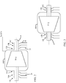
- FIG. 2 shows a schematic depiction of an embodiment of first steam turbine 4
- FIG. 3 shows a schematic depiction of an embodiment of second steam turbine 6, each including a double shell configuration.
- first steam turbine 4 and/or second steam turbine 6 can include a second, outer shell 100, which may have seal locations 14A, 14B, 14C as described with respect to FIG. 1 , sealing portions of outer shell 100 with respect to shaft 8. It is understood that first steam turbine 4 and/or second steam turbine 6 can include single or double-shell configurations according to any embodiments disclosed herein.
- components described as being “coupled” to one another can be joined along one or more interfaces.
- these interfaces can include junctions between distinct components, and in other cases, these interfaces can include a solidly and/or integrally formed interconnection. That is, in some cases, components that are "coupled” to one another can be simultaneously formed to define a single continuous member.
- these coupled components can be formed as separate members and be subsequently joined through known processes (e.g., fastening, ultrasonic welding, bonding).
Landscapes
- Engineering & Computer Science (AREA)
- Mechanical Engineering (AREA)
- General Engineering & Computer Science (AREA)
- Chemical & Material Sciences (AREA)
- Combustion & Propulsion (AREA)
- Turbine Rotor Nozzle Sealing (AREA)
- Engine Equipment That Uses Special Cycles (AREA)
- Sealing Using Fluids, Sealing Without Contact, And Removal Of Oil (AREA)
Applications Claiming Priority (1)
| Application Number | Priority Date | Filing Date | Title |
|---|---|---|---|
| US15/258,080 US10577962B2 (en) | 2016-09-07 | 2016-09-07 | Turbomachine temperature control system |
Publications (3)
| Publication Number | Publication Date |
|---|---|
| EP3293371A2 true EP3293371A2 (fr) | 2018-03-14 |
| EP3293371A3 EP3293371A3 (fr) | 2018-06-20 |
| EP3293371B1 EP3293371B1 (fr) | 2019-06-12 |
Family
ID=59829193
Family Applications (1)
| Application Number | Title | Priority Date | Filing Date |
|---|---|---|---|
| EP17189512.1A Active EP3293371B1 (fr) | 2016-09-07 | 2017-09-05 | Système de régulation de température d'une turbomachine |
Country Status (3)
| Country | Link |
|---|---|
| US (1) | US10577962B2 (fr) |
| EP (1) | EP3293371B1 (fr) |
| CN (1) | CN107795340B (fr) |
Families Citing this family (2)
| Publication number | Priority date | Publication date | Assignee | Title |
|---|---|---|---|---|
| CN110332017B (zh) * | 2019-08-08 | 2022-04-22 | 国家电投集团河南电力有限公司 | 一种自适应轴封供汽系统 |
| CN112392554B (zh) * | 2020-11-16 | 2023-03-24 | 广州粤能电力科技开发有限公司 | 汽机轴封供汽控制方法、装置、系统和计算机设备 |
Family Cites Families (40)
| Publication number | Priority date | Publication date | Assignee | Title |
|---|---|---|---|---|
| US3194020A (en) * | 1963-03-25 | 1965-07-13 | Combustion Eng | Method and apparatus relating to vapor generation |
| US3604206A (en) * | 1968-07-31 | 1971-09-14 | Gen Electric | Shaft-sealing system for nuclear turbines |
| US4353216A (en) | 1980-09-29 | 1982-10-12 | General Electric Company | Forward-reverse flow control system for a bypass steam turbine |
| US4398393A (en) * | 1981-09-25 | 1983-08-16 | General Electric Company | Steam turbine control apparatus |
| JPS61237802A (ja) * | 1985-04-12 | 1986-10-23 | Hitachi Ltd | 蒸気タ−ビンの暖機方法 |
| CH671807A5 (fr) * | 1986-08-11 | 1989-09-29 | Proizv Ob Turbostroenia | |
| CN1013289B (zh) * | 1987-04-24 | 1991-07-24 | 吴义松 | 可调节汽缸散热量的汽轮机汽缸保温法 |
| US5412936A (en) | 1992-12-30 | 1995-05-09 | General Electric Co. | Method of effecting start-up of a cold steam turbine system in a combined cycle plant |
| JP4707927B2 (ja) | 2000-05-31 | 2011-06-22 | シーメンス アクチエンゲゼルシヤフト | 多段蒸気タービンの無負荷又は軽負荷運転時の運転方法と装置 |
| DE10227709B4 (de) | 2001-06-25 | 2011-07-21 | Alstom Technology Ltd. | Dampfturbinenanlage sowie Verfahren zu deren Betrieb |
| JP4209150B2 (ja) * | 2002-07-16 | 2009-01-14 | 三菱重工業株式会社 | 複合発電設備 |
| US6782703B2 (en) | 2002-09-11 | 2004-08-31 | Siemens Westinghouse Power Corporation | Apparatus for starting a combined cycle power plant |
| EP1674667A1 (fr) | 2004-12-21 | 2006-06-28 | Siemens Aktiengesellschaft | Procédé et dispositif pour le préchauffage d'une turbine à vapeur |
| EP1744020A1 (fr) | 2005-07-14 | 2007-01-17 | Siemens Aktiengesellschaft | Procédé de démarrage d'une installation de turbines à vapeur |
| EP1775429A1 (fr) | 2005-10-12 | 2007-04-18 | Siemens Aktiengesellschaft | Procédé pour chauffer und turbine à vapeur |
| EP1775431A1 (fr) | 2005-10-12 | 2007-04-18 | Siemens Aktiengesellschaft | Procédé pour chauffer und turbine à vapeur |
| EP1992794A1 (fr) | 2007-03-06 | 2008-11-19 | Siemens Aktiengesellschaft | Installation de cycle combiné et procédé destiné au démarrage d'une installation de cycle combiné |
| JP2010019190A (ja) * | 2008-07-11 | 2010-01-28 | Toshiba Corp | 蒸気タービンおよび蒸気タービンの冷却方法 |
| JP2011001935A (ja) * | 2009-06-22 | 2011-01-06 | Hitachi Ltd | シール蒸気供給系統及びその制御方法 |
| US8843240B2 (en) | 2010-11-30 | 2014-09-23 | General Electric Company | Loading a steam turbine based on flow and temperature ramping rates |
| ITMI20102463A1 (it) * | 2010-12-30 | 2012-07-01 | Stamicarbon | Metodo per l'avviamento e la gestione di un impianto termico a ciclo combinato per la produzione di energia e relativo impianto |
| PL2492456T3 (pl) | 2011-02-25 | 2016-10-31 | System turbiny parowej oraz sposób sterowania przepływem pary w systemie turbiny parowej | |
| JP2012207594A (ja) * | 2011-03-30 | 2012-10-25 | Mitsubishi Heavy Ind Ltd | 回転機械のロータ及び回転機械 |
| EP2511485A1 (fr) | 2011-04-15 | 2012-10-17 | Siemens Aktiengesellschaft | Turbomachine, installation à turbine à vapeur, et procédé de chauffage d'un arbre de turbine à vapeur |
| US8899909B2 (en) * | 2011-06-27 | 2014-12-02 | General Electric Company | Systems and methods for steam turbine wheel space cooling |
| DE202011105609U1 (de) * | 2011-09-12 | 2011-10-13 | Alstom Technology Ltd. | Labyrinthdichtung |
| EP2573332A1 (fr) | 2011-09-21 | 2013-03-27 | Siemens Aktiengesellschaft | Eolienne dotée d'un chauffage électrique interne |
| US8893507B2 (en) * | 2011-11-04 | 2014-11-25 | General Electric Company | Method for controlling gas turbine rotor temperature during periods of extended downtime |
| DE102012200769A1 (de) | 2012-01-19 | 2013-07-25 | Siemens Aktiengesellschaft | Verfahren für das Anfahren einer Dampfturbine eines Solarkraftwerkes |
| EP2644840A1 (fr) * | 2012-03-28 | 2013-10-02 | Siemens Aktiengesellschaft | Système de turbines à vapeur et procédé de démarrage d'une turbine à vapeur |
| ITCO20120020A1 (it) * | 2012-04-27 | 2013-10-28 | Nuovo Pignone Srl | Compressore, alimentazione del gas di tenuta e metodo |
| EP2657467A1 (fr) | 2012-04-27 | 2013-10-30 | Siemens Aktiengesellschaft | Refroidissement forcé pour installations de turbines à vapeur |
| EP2738360B1 (fr) | 2012-12-03 | 2019-06-12 | General Electric Technology GmbH | Dispositif de réchauffage de turbine à vapeur d'une centrale électrique |
| US9719418B2 (en) * | 2013-04-01 | 2017-08-01 | General Electric Company | Turbomachine inlet bleed heating assembly |
| US9032733B2 (en) * | 2013-04-04 | 2015-05-19 | General Electric Company | Turbomachine system with direct header steam injection, related control system and program product |
| CN103758586A (zh) * | 2013-12-05 | 2014-04-30 | 镇江茂源环保科技有限公司 | 一种汽轮机快速冷却系统 |
| US9719427B2 (en) * | 2014-01-21 | 2017-08-01 | Solar Turbines Incorporated | Turbine blade platform seal assembly validation |
| DE102014210225A1 (de) * | 2014-05-28 | 2015-12-03 | Siemens Aktiengesellschaft | Dampfturbinensystem |
| US20160040596A1 (en) * | 2014-08-08 | 2016-02-11 | General Electric Company | Turbomachine system including an inlet bleed heat system and method of operating a turbomachine at part load |
| DE102014221676A1 (de) | 2014-10-24 | 2016-04-28 | Siemens Aktiengesellschaft | Warmhalte-Konzept für schnelles Anfahren der Dampfturbine in GuD-Kraftwerken: Einsatz von Inertgas |
-
2016
- 2016-09-07 US US15/258,080 patent/US10577962B2/en active Active
-
2017
- 2017-09-05 EP EP17189512.1A patent/EP3293371B1/fr active Active
- 2017-09-07 CN CN201710799695.8A patent/CN107795340B/zh active Active
Non-Patent Citations (1)
| Title |
|---|
| None |
Also Published As
| Publication number | Publication date |
|---|---|
| CN107795340B (zh) | 2022-03-08 |
| US20180066534A1 (en) | 2018-03-08 |
| US10577962B2 (en) | 2020-03-03 |
| EP3293371A3 (fr) | 2018-06-20 |
| EP3293371B1 (fr) | 2019-06-12 |
| CN107795340A (zh) | 2018-03-13 |
Similar Documents
| Publication | Publication Date | Title |
|---|---|---|
| EP3653849B1 (fr) | Procédé de chauffage de turbine à vapeur | |
| EP3354865B1 (fr) | Système de préchauffage de turbine à vapeur avec un générateur de vapeur | |
| US8984893B2 (en) | System and method for augmenting gas turbine power output | |
| US20100310356A1 (en) | Clutched steam turbine low pressure sections and methods therefore | |
| EP1050666B1 (fr) | Système de refroidissement à vapeur pour piston d'allègement d'une turbine à vapeur et méthode associée | |
| JP2014510872A (ja) | 有機ランキンサイクルにおいて用いられるターボエクスパンダのための封止システム | |
| JPS62251409A (ja) | 1軸コンバインドプラントにおける蒸気タービンのクーリング方法及びクーリング装置 | |
| US9945266B2 (en) | Combined cycle power plant thermal energy conservation | |
| EP3354877B1 (fr) | Système de préchauffage de turbine à vapeur | |
| EP3315742B1 (fr) | Système de chauffage de carburant utilisant de la vapeur et de l'eau dans un seul échangeur de chaleur pour carburant | |
| JP7167136B2 (ja) | 蒸気タービンプラント、及びその冷却方法 | |
| EP3293371B1 (fr) | Système de régulation de température d'une turbomachine | |
| US20150372214A1 (en) | Cooled cooling air system having thermoelectric generator | |
| US9464537B2 (en) | Clutched turbine wheels | |
| US9482116B2 (en) | Active cold-reheat temperature control system | |
| US9464534B2 (en) | Turbine purge flow control system and related method of operation | |
| KR102632781B1 (ko) | 복합 사이클 발전소 시스템 내의 열회수 증기 발생기의 열응력 감소를 위한 구성 요소 및 시스템 | |
| EP2492456B1 (fr) | Système de turbine à vapeur et procédé pour contrôler le débit de vapeur d'un système de turbine à vapeur | |
| JP4509815B2 (ja) | 抽気背圧蒸気タービン設備およびその運転方法 | |
| KR20160112309A (ko) | 누설 유체를 재생하는 터보 팽창기 | |
| US20170306852A1 (en) | Electrical and mechanical connections through firewall | |
| JPS5896102A (ja) | 蒸気タ−ビンロ−タの暖機方法及びその装置 | |
| JP2011001935A (ja) | シール蒸気供給系統及びその制御方法 | |
| US20160230608A1 (en) | Single shaft combined cycle power plant shaft arrangement | |
| CN107889514A (zh) | 用于冷却蒸汽轮机的方法 |
Legal Events
| Date | Code | Title | Description |
|---|---|---|---|
| PUAI | Public reference made under article 153(3) epc to a published international application that has entered the european phase |
Free format text: ORIGINAL CODE: 0009012 |
|
| STAA | Information on the status of an ep patent application or granted ep patent |
Free format text: STATUS: THE APPLICATION HAS BEEN PUBLISHED |
|
| AK | Designated contracting states |
Kind code of ref document: A2 Designated state(s): AL AT BE BG CH CY CZ DE DK EE ES FI FR GB GR HR HU IE IS IT LI LT LU LV MC MK MT NL NO PL PT RO RS SE SI SK SM TR |
|
| AX | Request for extension of the european patent |
Extension state: BA ME |
|
| PUAL | Search report despatched |
Free format text: ORIGINAL CODE: 0009013 |
|
| AK | Designated contracting states |
Kind code of ref document: A3 Designated state(s): AL AT BE BG CH CY CZ DE DK EE ES FI FR GB GR HR HU IE IS IT LI LT LU LV MC MK MT NL NO PL PT RO RS SE SI SK SM TR |
|
| AX | Request for extension of the european patent |
Extension state: BA ME |
|
| RIC1 | Information provided on ipc code assigned before grant |
Ipc: F01K 13/02 20060101AFI20180517BHEP |
|
| STAA | Information on the status of an ep patent application or granted ep patent |
Free format text: STATUS: REQUEST FOR EXAMINATION WAS MADE |
|
| 17P | Request for examination filed |
Effective date: 20181220 |
|
| RBV | Designated contracting states (corrected) |
Designated state(s): AL AT BE BG CH CY CZ DE DK EE ES FI FR GB GR HR HU IE IS IT LI LT LU LV MC MK MT NL NO PL PT RO RS SE SI SK SM TR |
|
| GRAP | Despatch of communication of intention to grant a patent |
Free format text: ORIGINAL CODE: EPIDOSNIGR1 |
|
| STAA | Information on the status of an ep patent application or granted ep patent |
Free format text: STATUS: GRANT OF PATENT IS INTENDED |
|
| INTG | Intention to grant announced |
Effective date: 20190221 |
|
| GRAS | Grant fee paid |
Free format text: ORIGINAL CODE: EPIDOSNIGR3 |
|
| GRAA | (expected) grant |
Free format text: ORIGINAL CODE: 0009210 |
|
| STAA | Information on the status of an ep patent application or granted ep patent |
Free format text: STATUS: THE PATENT HAS BEEN GRANTED |
|
| AK | Designated contracting states |
Kind code of ref document: B1 Designated state(s): AL AT BE BG CH CY CZ DE DK EE ES FI FR GB GR HR HU IE IS IT LI LT LU LV MC MK MT NL NO PL PT RO RS SE SI SK SM TR |
|
| REG | Reference to a national code |
Ref country code: GB Ref legal event code: FG4D |
|
| REG | Reference to a national code |
Ref country code: CH Ref legal event code: EP |
|
| REG | Reference to a national code |
Ref country code: AT Ref legal event code: REF Ref document number: 1142817 Country of ref document: AT Kind code of ref document: T Effective date: 20190615 |
|
| REG | Reference to a national code |
Ref country code: DE Ref legal event code: R096 Ref document number: 602017004448 Country of ref document: DE |
|
| REG | Reference to a national code |
Ref country code: IE Ref legal event code: FG4D |
|
| REG | Reference to a national code |
Ref country code: NL Ref legal event code: MP Effective date: 20190612 |
|
| REG | Reference to a national code |
Ref country code: LT Ref legal event code: MG4D |
|
| PG25 | Lapsed in a contracting state [announced via postgrant information from national office to epo] |
Ref country code: AL Free format text: LAPSE BECAUSE OF FAILURE TO SUBMIT A TRANSLATION OF THE DESCRIPTION OR TO PAY THE FEE WITHIN THE PRESCRIBED TIME-LIMIT Effective date: 20190612 Ref country code: NO Free format text: LAPSE BECAUSE OF FAILURE TO SUBMIT A TRANSLATION OF THE DESCRIPTION OR TO PAY THE FEE WITHIN THE PRESCRIBED TIME-LIMIT Effective date: 20190912 Ref country code: HR Free format text: LAPSE BECAUSE OF FAILURE TO SUBMIT A TRANSLATION OF THE DESCRIPTION OR TO PAY THE FEE WITHIN THE PRESCRIBED TIME-LIMIT Effective date: 20190612 Ref country code: LT Free format text: LAPSE BECAUSE OF FAILURE TO SUBMIT A TRANSLATION OF THE DESCRIPTION OR TO PAY THE FEE WITHIN THE PRESCRIBED TIME-LIMIT Effective date: 20190612 Ref country code: SE Free format text: LAPSE BECAUSE OF FAILURE TO SUBMIT A TRANSLATION OF THE DESCRIPTION OR TO PAY THE FEE WITHIN THE PRESCRIBED TIME-LIMIT Effective date: 20190612 Ref country code: FI Free format text: LAPSE BECAUSE OF FAILURE TO SUBMIT A TRANSLATION OF THE DESCRIPTION OR TO PAY THE FEE WITHIN THE PRESCRIBED TIME-LIMIT Effective date: 20190612 |
|
| PG25 | Lapsed in a contracting state [announced via postgrant information from national office to epo] |
Ref country code: LV Free format text: LAPSE BECAUSE OF FAILURE TO SUBMIT A TRANSLATION OF THE DESCRIPTION OR TO PAY THE FEE WITHIN THE PRESCRIBED TIME-LIMIT Effective date: 20190612 Ref country code: RS Free format text: LAPSE BECAUSE OF FAILURE TO SUBMIT A TRANSLATION OF THE DESCRIPTION OR TO PAY THE FEE WITHIN THE PRESCRIBED TIME-LIMIT Effective date: 20190612 Ref country code: BG Free format text: LAPSE BECAUSE OF FAILURE TO SUBMIT A TRANSLATION OF THE DESCRIPTION OR TO PAY THE FEE WITHIN THE PRESCRIBED TIME-LIMIT Effective date: 20190912 Ref country code: GR Free format text: LAPSE BECAUSE OF FAILURE TO SUBMIT A TRANSLATION OF THE DESCRIPTION OR TO PAY THE FEE WITHIN THE PRESCRIBED TIME-LIMIT Effective date: 20190913 |
|
| REG | Reference to a national code |
Ref country code: AT Ref legal event code: MK05 Ref document number: 1142817 Country of ref document: AT Kind code of ref document: T Effective date: 20190612 |
|
| PG25 | Lapsed in a contracting state [announced via postgrant information from national office to epo] |
Ref country code: PT Free format text: LAPSE BECAUSE OF FAILURE TO SUBMIT A TRANSLATION OF THE DESCRIPTION OR TO PAY THE FEE WITHIN THE PRESCRIBED TIME-LIMIT Effective date: 20191014 Ref country code: SK Free format text: LAPSE BECAUSE OF FAILURE TO SUBMIT A TRANSLATION OF THE DESCRIPTION OR TO PAY THE FEE WITHIN THE PRESCRIBED TIME-LIMIT Effective date: 20190612 Ref country code: EE Free format text: LAPSE BECAUSE OF FAILURE TO SUBMIT A TRANSLATION OF THE DESCRIPTION OR TO PAY THE FEE WITHIN THE PRESCRIBED TIME-LIMIT Effective date: 20190612 Ref country code: AT Free format text: LAPSE BECAUSE OF FAILURE TO SUBMIT A TRANSLATION OF THE DESCRIPTION OR TO PAY THE FEE WITHIN THE PRESCRIBED TIME-LIMIT Effective date: 20190612 Ref country code: CZ Free format text: LAPSE BECAUSE OF FAILURE TO SUBMIT A TRANSLATION OF THE DESCRIPTION OR TO PAY THE FEE WITHIN THE PRESCRIBED TIME-LIMIT Effective date: 20190612 Ref country code: NL Free format text: LAPSE BECAUSE OF FAILURE TO SUBMIT A TRANSLATION OF THE DESCRIPTION OR TO PAY THE FEE WITHIN THE PRESCRIBED TIME-LIMIT Effective date: 20190612 Ref country code: RO Free format text: LAPSE BECAUSE OF FAILURE TO SUBMIT A TRANSLATION OF THE DESCRIPTION OR TO PAY THE FEE WITHIN THE PRESCRIBED TIME-LIMIT Effective date: 20190612 |
|
| PG25 | Lapsed in a contracting state [announced via postgrant information from national office to epo] |
Ref country code: ES Free format text: LAPSE BECAUSE OF FAILURE TO SUBMIT A TRANSLATION OF THE DESCRIPTION OR TO PAY THE FEE WITHIN THE PRESCRIBED TIME-LIMIT Effective date: 20190612 Ref country code: IT Free format text: LAPSE BECAUSE OF FAILURE TO SUBMIT A TRANSLATION OF THE DESCRIPTION OR TO PAY THE FEE WITHIN THE PRESCRIBED TIME-LIMIT Effective date: 20190612 Ref country code: IS Free format text: LAPSE BECAUSE OF FAILURE TO SUBMIT A TRANSLATION OF THE DESCRIPTION OR TO PAY THE FEE WITHIN THE PRESCRIBED TIME-LIMIT Effective date: 20191012 Ref country code: SM Free format text: LAPSE BECAUSE OF FAILURE TO SUBMIT A TRANSLATION OF THE DESCRIPTION OR TO PAY THE FEE WITHIN THE PRESCRIBED TIME-LIMIT Effective date: 20190612 |
|
| REG | Reference to a national code |
Ref country code: DE Ref legal event code: R097 Ref document number: 602017004448 Country of ref document: DE |
|
| PG25 | Lapsed in a contracting state [announced via postgrant information from national office to epo] |
Ref country code: TR Free format text: LAPSE BECAUSE OF FAILURE TO SUBMIT A TRANSLATION OF THE DESCRIPTION OR TO PAY THE FEE WITHIN THE PRESCRIBED TIME-LIMIT Effective date: 20190612 |
|
| PLBE | No opposition filed within time limit |
Free format text: ORIGINAL CODE: 0009261 |
|
| STAA | Information on the status of an ep patent application or granted ep patent |
Free format text: STATUS: NO OPPOSITION FILED WITHIN TIME LIMIT |
|
| PG25 | Lapsed in a contracting state [announced via postgrant information from national office to epo] |
Ref country code: PL Free format text: LAPSE BECAUSE OF FAILURE TO SUBMIT A TRANSLATION OF THE DESCRIPTION OR TO PAY THE FEE WITHIN THE PRESCRIBED TIME-LIMIT Effective date: 20190612 Ref country code: DK Free format text: LAPSE BECAUSE OF FAILURE TO SUBMIT A TRANSLATION OF THE DESCRIPTION OR TO PAY THE FEE WITHIN THE PRESCRIBED TIME-LIMIT Effective date: 20190612 |
|
| 26N | No opposition filed |
Effective date: 20200313 |
|
| PG25 | Lapsed in a contracting state [announced via postgrant information from national office to epo] |
Ref country code: SI Free format text: LAPSE BECAUSE OF FAILURE TO SUBMIT A TRANSLATION OF THE DESCRIPTION OR TO PAY THE FEE WITHIN THE PRESCRIBED TIME-LIMIT Effective date: 20190612 Ref country code: IS Free format text: LAPSE BECAUSE OF FAILURE TO SUBMIT A TRANSLATION OF THE DESCRIPTION OR TO PAY THE FEE WITHIN THE PRESCRIBED TIME-LIMIT Effective date: 20200224 Ref country code: MC Free format text: LAPSE BECAUSE OF FAILURE TO SUBMIT A TRANSLATION OF THE DESCRIPTION OR TO PAY THE FEE WITHIN THE PRESCRIBED TIME-LIMIT Effective date: 20190612 |
|
| PG2D | Information on lapse in contracting state deleted |
Ref country code: IS |
|
| PG25 | Lapsed in a contracting state [announced via postgrant information from national office to epo] |
Ref country code: IE Free format text: LAPSE BECAUSE OF NON-PAYMENT OF DUE FEES Effective date: 20190905 Ref country code: LU Free format text: LAPSE BECAUSE OF NON-PAYMENT OF DUE FEES Effective date: 20190905 |
|
| REG | Reference to a national code |
Ref country code: BE Ref legal event code: MM Effective date: 20190930 |
|
| PG25 | Lapsed in a contracting state [announced via postgrant information from national office to epo] |
Ref country code: BE Free format text: LAPSE BECAUSE OF NON-PAYMENT OF DUE FEES Effective date: 20190930 |
|
| REG | Reference to a national code |
Ref country code: CH Ref legal event code: PL |
|
| PG25 | Lapsed in a contracting state [announced via postgrant information from national office to epo] |
Ref country code: CY Free format text: LAPSE BECAUSE OF FAILURE TO SUBMIT A TRANSLATION OF THE DESCRIPTION OR TO PAY THE FEE WITHIN THE PRESCRIBED TIME-LIMIT Effective date: 20190612 |
|
| PG25 | Lapsed in a contracting state [announced via postgrant information from national office to epo] |
Ref country code: HU Free format text: LAPSE BECAUSE OF FAILURE TO SUBMIT A TRANSLATION OF THE DESCRIPTION OR TO PAY THE FEE WITHIN THE PRESCRIBED TIME-LIMIT; INVALID AB INITIO Effective date: 20170905 Ref country code: MT Free format text: LAPSE BECAUSE OF FAILURE TO SUBMIT A TRANSLATION OF THE DESCRIPTION OR TO PAY THE FEE WITHIN THE PRESCRIBED TIME-LIMIT Effective date: 20190612 |
|
| PG25 | Lapsed in a contracting state [announced via postgrant information from national office to epo] |
Ref country code: CH Free format text: LAPSE BECAUSE OF NON-PAYMENT OF DUE FEES Effective date: 20200930 Ref country code: LI Free format text: LAPSE BECAUSE OF NON-PAYMENT OF DUE FEES Effective date: 20200930 |
|
| PG25 | Lapsed in a contracting state [announced via postgrant information from national office to epo] |
Ref country code: MK Free format text: LAPSE BECAUSE OF FAILURE TO SUBMIT A TRANSLATION OF THE DESCRIPTION OR TO PAY THE FEE WITHIN THE PRESCRIBED TIME-LIMIT Effective date: 20190612 |
|
| P01 | Opt-out of the competence of the unified patent court (upc) registered |
Effective date: 20230523 |
|
| REG | Reference to a national code |
Ref country code: DE Ref legal event code: R081 Ref document number: 602017004448 Country of ref document: DE Owner name: ARABELLE SOLUTIONS FRANCE, FR Free format text: FORMER OWNER: GENERAL ELECTRIC CO., SCHENECTADY, N.Y., US Ref country code: DE Ref legal event code: R081 Ref document number: 602017004448 Country of ref document: DE Owner name: ARABELLE TECHNOLOGIES, FR Free format text: FORMER OWNER: GENERAL ELECTRIC CO., SCHENECTADY, N.Y., US Ref country code: DE Ref legal event code: R082 Ref document number: 602017004448 Country of ref document: DE Ref country code: DE Ref legal event code: R081 Ref document number: 602017004448 Country of ref document: DE Owner name: GENERAL ELECTRIC TECHNOLOGY GMBH, CH Free format text: FORMER OWNER: GENERAL ELECTRIC CO., SCHENECTADY, N.Y., US |
|
| REG | Reference to a national code |
Ref country code: GB Ref legal event code: 732E Free format text: REGISTERED BETWEEN 20240502 AND 20240508 |
|
| REG | Reference to a national code |
Ref country code: DE Ref legal event code: R081 Ref document number: 602017004448 Country of ref document: DE Owner name: ARABELLE SOLUTIONS FRANCE, FR Free format text: FORMER OWNER: GENERAL ELECTRIC TECHNOLOGY GMBH, BADEN, CH Ref country code: DE Ref legal event code: R081 Ref document number: 602017004448 Country of ref document: DE Owner name: ARABELLE TECHNOLOGIES, FR Free format text: FORMER OWNER: GENERAL ELECTRIC TECHNOLOGY GMBH, BADEN, CH |
|
| REG | Reference to a national code |
Ref country code: GB Ref legal event code: 732E Free format text: REGISTERED BETWEEN 20250213 AND 20250219 |
|
| REG | Reference to a national code |
Ref country code: DE Ref legal event code: R081 Ref document number: 602017004448 Country of ref document: DE Owner name: ARABELLE SOLUTIONS FRANCE, FR Free format text: FORMER OWNER: ARABELLE TECHNOLOGIES, BOULOGNE-BILLANCOURT, FR |
|
| REG | Reference to a national code |
Ref country code: GB Ref legal event code: 732E Free format text: REGISTERED BETWEEN 20250619 AND 20250625 |
|
| PGFP | Annual fee paid to national office [announced via postgrant information from national office to epo] |
Ref country code: DE Payment date: 20250820 Year of fee payment: 9 |
|
| PGFP | Annual fee paid to national office [announced via postgrant information from national office to epo] |
Ref country code: GB Payment date: 20250820 Year of fee payment: 9 |
|
| PGFP | Annual fee paid to national office [announced via postgrant information from national office to epo] |
Ref country code: FR Payment date: 20250820 Year of fee payment: 9 |