EP3293389B1 - Dispositif motopropulseur d'une fusée - Google Patents
Dispositif motopropulseur d'une fusée Download PDFInfo
- Publication number
- EP3293389B1 EP3293389B1 EP17187938.0A EP17187938A EP3293389B1 EP 3293389 B1 EP3293389 B1 EP 3293389B1 EP 17187938 A EP17187938 A EP 17187938A EP 3293389 B1 EP3293389 B1 EP 3293389B1
- Authority
- EP
- European Patent Office
- Prior art keywords
- chamber
- gas
- engine device
- control
- outlet opening
- Prior art date
- Legal status (The legal status is an assumption and is not a legal conclusion. Google has not performed a legal analysis and makes no representation as to the accuracy of the status listed.)
- Active
Links
Images


Classifications
-
- F—MECHANICAL ENGINEERING; LIGHTING; HEATING; WEAPONS; BLASTING
- F02—COMBUSTION ENGINES; HOT-GAS OR COMBUSTION-PRODUCT ENGINE PLANTS
- F02K—JET-PROPULSION PLANTS
- F02K9/00—Rocket-engine plants, i.e. plants carrying both fuel and oxidant therefor; Control thereof
- F02K9/97—Rocket nozzles
- F02K9/978—Closures for nozzles; Nozzles comprising ejectable or discardable elements
-
- F—MECHANICAL ENGINEERING; LIGHTING; HEATING; WEAPONS; BLASTING
- F02—COMBUSTION ENGINES; HOT-GAS OR COMBUSTION-PRODUCT ENGINE PLANTS
- F02K—JET-PROPULSION PLANTS
- F02K9/00—Rocket-engine plants, i.e. plants carrying both fuel and oxidant therefor; Control thereof
- F02K9/80—Rocket-engine plants, i.e. plants carrying both fuel and oxidant therefor; Control thereof characterised by thrust or thrust vector control
- F02K9/86—Rocket-engine plants, i.e. plants carrying both fuel and oxidant therefor; Control thereof characterised by thrust or thrust vector control using nozzle throats of adjustable cross- section
-
- F—MECHANICAL ENGINEERING; LIGHTING; HEATING; WEAPONS; BLASTING
- F05—INDEXING SCHEMES RELATING TO ENGINES OR PUMPS IN VARIOUS SUBCLASSES OF CLASSES F01-F04
- F05D—INDEXING SCHEME FOR ASPECTS RELATING TO NON-POSITIVE-DISPLACEMENT MACHINES OR ENGINES, GAS-TURBINES OR JET-PROPULSION PLANTS
- F05D2220/00—Application
- F05D2220/80—Application in supersonic vehicles excluding hypersonic vehicles or ram, scram or rocket propulsion
-
- F—MECHANICAL ENGINEERING; LIGHTING; HEATING; WEAPONS; BLASTING
- F05—INDEXING SCHEMES RELATING TO ENGINES OR PUMPS IN VARIOUS SUBCLASSES OF CLASSES F01-F04
- F05D—INDEXING SCHEME FOR ASPECTS RELATING TO NON-POSITIVE-DISPLACEMENT MACHINES OR ENGINES, GAS-TURBINES OR JET-PROPULSION PLANTS
- F05D2270/00—Control
- F05D2270/30—Control parameters, e.g. input parameters
- F05D2270/306—Mass flow
- F05D2270/3061—Mass flow of the working fluid
Definitions
- the present invention relates to an engine device of a rocket engine.
- interceptor missiles are brought to collision with the ballistic targets to be destroyed, with the kinetic energy which is converted in the collision destroying the target.
- targets themselves move at high speeds and on only partially predictable trajectories, so that highly agile control of the interceptor missile is essential.
- reactive transverse thrust and position control systems are usually used. These systems can be operated by discrete thrust pulses, whereby the engines are switched on and off. In this case, the thrust is only used to correct course. In addition, continuous thrust controls are available, which allow precise adjustment of the thrust.
- nozzle needle that is to say an elongated body
- the nozzle needle being displaced mechanically in the axial direction.
- the US 6 227 247 B1 describes an engine valve with a piston continuously positionable between a closed and a maximum open position.
- the piston moves in response to the pressure differential between the pressure in the intermediate ring and the pressure behind the piston.
- a pivoting flap valve regulates this pressure difference.
- the invention accordingly relates to an engine device of a rocket engine, which comprises an afterburning chamber which has a gas inlet opening for a gas to flow into the afterburning chamber, and a gas outlet opening or nozzle which is designed to allow the gas to flow out of the afterburning chamber.
- the engine device further comprises an equalization chamber that can be filled with gas and a control chamber that can be filled with gas.
- a nozzle needle is arranged in an axially displaceable manner in such a way that a first end region of the nozzle needle can at least partially be introduced into the gas outlet opening.
- a second end region of the nozzle needle has a piston device, a first section of the piston device being arranged in the compensation chamber and being pressurized by a gas in the compensation chamber in such a way that the nozzle needle experiences an axial force in the direction of the gas outlet opening.
- a second section of the piston device is arranged in the control chamber and can be subjected to pressure by filling a gas into the control chamber in such a way that the nozzle needle experiences an axial force in the direction away from the gas outlet opening.
- the afterburning chamber is separated from the control chamber by a bulkhead.
- the control chamber has a gas opening through which gas can be introduced or discharged into the control chamber.
- the piston device can be displaced in an intermediate chamber arranged between the control chamber and the compensation chamber, the intermediate chamber being fluidically connected to ambient air.
- the position of the nozzle needle can be precisely adjusted.
- the pneumatic control achieves a very short setting time, so that the effective cross-section of the gas outlet opening of the afterburning chamber is extremely fast can be varied. This allows the thrust of the engine device to be adjusted precisely.
- the engine device has a control device which is designed to adjust an axial position of the nozzle needle by changing a gas pressure of a gas located in the control chamber.
- a control device which is designed to adjust an axial position of the nozzle needle by changing a gas pressure of a gas located in the control chamber.
- control device is also designed to set a gas pressure of a gas in the compensation chamber. As a result, both the axial force on the nozzle needle in the direction of the gas outlet opening and away from the gas outlet opening can be adjusted.
- the engine device has a sensor device which is designed to measure an axial position of the nozzle needle.
- the control device can set the gas pressure of the gas in the control chamber and / or compensation chamber in such a way that the nozzle needle is displaced into a predetermined axial position.
- the afterburning chamber is fluidically connected to the compensation chamber.
- the pressure in the afterburning chamber essentially corresponds to the pressure in the compensation chamber, apart from dynamic fluctuations due to the displacement of the nozzle needle and the flow losses due to the overflow of gas quantities.
- the afterburning chamber is preferably designed in such a way that in the case in which the control chamber is ventilated, i.e. not exposed to a gas, an axial force on the nozzle needle in the direction of the gas outlet opening is greater than that due to the flow of the gas in the afterburning chamber axial force exerted on the nozzle needle away from the gas outlet opening.
- the control chamber is used to build up a counterforce which moves the nozzle needle away from the gas outlet opening. Since only the pressure difference is required for this, the nozzle needle is displaced axially by the application of a low gas pressure, so that a low Changing the gas pressure is sufficient to set the exact axial position of the nozzle needle. This keeps the positioning time very short.
- control chamber is arranged in the axial direction between the compensation chamber and the afterburning chamber.
- the axial direction corresponds to the axial displacement direction of the nozzle needle.
- the compensation chamber and / or the afterburning chamber are arranged symmetrically around an axial displacement axis of the nozzle needle.
- the gas outlet opening can be completely closed by inserting the nozzle needle.
- the thrust provided by the engine device can thus be varied continuously between zero and a maximum predetermined value, the maximum value corresponding to a position in which the nozzle needle is completely displaced out of the gas outlet opening.
- FIG. 1 A schematic side view of an engine device 100 is shown, which has a housing with a front housing section 11 and a rear housing section 12.
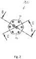
- Figure 2 shows a rear view of the in Figure 1 engine device shown.
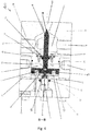
- FIG. 10 is a cross-sectional view of the engine device 100 taken along the line in FIG Figure 1 illustrated axis AA.
- Figure 4 shows the engine device in a schematic cross-sectional view along the axis BB of FIG Figure 2 and Figure 5 along the axis CC of the Figure 2 .
- the engine device 100 has an afterburning chamber 1 which is connected to a gas reservoir or a gas generator via gas inlet openings 27.
- the gas reservoir or the gas generator introduces gas into the afterburning chamber 1, which gas is accelerated through a gas outlet opening or engine nozzle 20 and discharged from the afterburning chamber 1 becomes.
- the discharged gas generates a thrust by means of which the flight direction of a missile having the propulsion unit can be changed.
- the thrust is varied by changing an effective cross section of the gas outlet opening 20.
- a nozzle needle 4 is arranged axially displaceably in the engine device 100, a first end region 28 of the nozzle needle 4 being at least partially insertable into the gas outlet opening 20, so that the effective Cross section of the gas outlet opening 20 is variable.
- the nozzle needle has a cylindrical section which tapers in the first end region 28.
- the end region 28 preferably tapers to a point.
- the end region can also be rounded or likewise cylindrical.
- the gas outlet opening 20 can preferably be completely closed by inserting the nozzle needle 4.
- the afterburning chamber 1 is separated from a control chamber 2 by a bulkhead 10. Seals 25, 26 are arranged between the bulkhead 10 and the housing. A seal retaining plate 15 is screwed to the bulkhead 10 by means of seal retaining screws 16, a nozzle needle seal 13 being fastened to the seal retaining plate 15. The nozzle needle 4 is inserted through the nozzle needle seal 13 and the seal holding plate 15 into the afterburning chamber 1 and is axially displaceable, the afterburning chamber 1 being sealed by the nozzle needle seal 13.
- the engine device 100 furthermore has a compensation chamber 3, the control chamber 2 being arranged in the axial direction between the afterburning chamber 1 and the compensation chamber 3.
- An intermediate chamber 30 is arranged between the compensation chamber 3 and the control chamber 2.
- the compensation chamber 3 and / or the afterburning chamber 1 are preferably arranged symmetrically around an axial displacement axis of the nozzle needle 4.
- the nozzle needle 4 has a piston device 5 at a second end region which is axially opposite to the first end region 28.
- the piston device 5 comprises a first section 29, which is arranged in the compensation chamber 3 so as to be axially displaceable and form-fitting.
- the piston device 5 further comprises a second section 7 which is arranged in the control chamber 2 in an axially displaceable and form-fitting manner.
- the first section 29 is via a piston screw 8 with the second section 7 of the Piston device 5 connected.
- a third section 6 faces away from the afterburning chamber 1 and is axially displaceable and arranged in a form-fitting manner in the intermediate chamber 30.
- piston seals 9 are enclosed in a radially outer direction, which prevent fluidic contact between the control chamber 2 and the intermediate chamber 30.
- Further seals 14 are arranged between the rear housing section 12 and a cylindrical protuberance of the third section 6 of the piston device 5, so that the cylindrical protuberance in the compensation chamber 3 can be moved in the axial direction and at the same time the compensation chamber 3 is sealed off from the intermediate chamber 30.
- the intermediate chamber 30 is fluidically connected to an ambient air via vent openings 21, so that a neutral ambient pressure prevails in the intermediate chamber 30 and the nozzle needle 4 can be displaced in the axial direction in the intermediate chamber 30 without any air in the intermediate chamber 30 exerting an axial force the nozzle needle 4 exerts.
- the afterburning chamber 1 is preferably fluidically connected to the compensation chamber 3.
- the compensation chamber 3 and the afterburning chamber 1 can be connected to the same gas reservoir or gas generator, or the afterburning chamber 1 and the compensation chamber 3 can be connected to one another via a fluid line or gas line.
- the piston device 5 has a sensor connection 17 which can be or is connected to a sensor device which can also be part of the engine device 100.
- the sensor device can be screwed to a screw hole 23 of the rear housing section 12 by means of screws and fastened thereto.
- the sensor device is designed to measure an axial position of the nozzle needle 4.
- the afterburning chamber 1 also has a connection 18 which can be or is connected to a pressure / temperature measuring transducer, which can also be part of the engine device 100.
- the pressure / temperature transducer is designed to measure a pressure or a temperature in the afterburning chamber 1.
- the control chamber 2 also has a connection 19 which can be or is connected to a pressure / temperature transducer which is connected to the pressure / temperature transducer connected to the connection 18 of the afterburning chamber 1 can be identical or different from this.
- the pressure / temperature transducer is designed to measure a pressure or a temperature in the control chamber 2 and can likewise be part of the engine device 100.
- a gas located in the compensation chamber 3 pressurizes the first section 29 of the piston device 5 in such a way that the nozzle needle 4 has an in Figure 5
- the axial compensating force F A drawn in the direction of the gas outlet opening 20 of the afterburning chamber 1 is experienced. Due to the air flow through the gas outlet opening 20 of the afterburning chamber 1, the first end region 28 of the nozzle needle 4 is also subjected to pressure so that an air force F L is exerted away from the gas outlet opening 20 on the nozzle needle 4.
- the compensation chamber is preferably dimensioned, i.e. a size and / or geometric shape of the compensation chamber is selected such that the compensation force F A when the nozzle needle is completely retracted, i.e. in a position in which the nozzle needle 4 is maximally far out of the gas outlet opening 20 of the Afterburning chamber 1 is moved out, greater than the air force F L. In this case, this creates an effective force in the direction of the gas outlet opening 20.
- the control chamber 2 has a gas opening 24, via which gas can be introduced or discharged into the control chamber 2.
- a control force F S can be generated on the nozzle needle 4, which is generated by the gas pressure of the gas in the control chamber 2 and points away from the gas outlet opening 20.
- the inflow and outflow of the gas into the control chamber 2 can take place through two 2/2-way valves or one 3/3-way valve.
- the engine device 100 preferably also has a control device (not shown) which is designed to adjust the axial position of the nozzle needle 4 by changing a gas pressure of a gas located in the control chamber 2.
- the control device is preferably connected to the sensor device and receives a current axial position of the nozzle needle 4 from the sensor device. Based on the current axial position of the nozzle needle 4, the control device increases or decreases the gas pressure of the gas in the control chamber 2 until the gas pressure of the Sensor device measured current axial position of a predetermined position corresponds.
- the control force F S which points away from the gas outlet opening 20, is increased, so that the nozzle needle 4 can be moved further out of the gas outlet opening 20 by increasing the gas pressure of the gas.
- control device can reduce the control force F S by reducing the gas pressure of the gas in the control chamber 2, so that the nozzle needle 4 is moved or inserted further into the gas outlet opening 20 due to the compensating force F A.
- the effective cross section of the gas outlet opening 20 is thereby reduced.
- the control device is thus designed to continuously change the axial position of the nozzle needle 4.
- control device can also be designed to set a pressure of a gas in the compensation chamber 3.
- the control device can preferably set both the gas pressure of the gas in the equalization chamber and the gas pressure of the gas in the control chamber 2.
- the order in which the compensation chamber 3, control chamber 2 and afterburning chamber 1 are arranged is also not limited to the embodiments shown.
- the compensation chamber 3 can be arranged between the control chamber 2 and the afterburning chamber 1.
Landscapes
- Engineering & Computer Science (AREA)
- Chemical & Material Sciences (AREA)
- Combustion & Propulsion (AREA)
- Mechanical Engineering (AREA)
- General Engineering & Computer Science (AREA)
- Testing Of Engines (AREA)
- Jet Pumps And Other Pumps (AREA)
- Output Control And Ontrol Of Special Type Engine (AREA)
Claims (8)
- Dispositif motopropulseur (100) d'une fusée, comportant :une chambre de postcombustion (1) dotée d'une ouverture d'admission de gaz (27) destinée à faire entrer un gaz dans la chambre de postcombustion (1) et d'une ouverture de sortie de gaz (20) destinée à faire sortir le gaz ;d'une chambre d'équilibrage (3) pouvant être remplie de gaz ; d'une chambre de pilotage (2) pouvant être remplie de gaz ; etd'une aiguille d'injection (4), laquelle est disposée en coulissement axial de telle sorte qu'une première zone d'extrémité (28) de l'aiguille d'injection (4) peut être introduite au moins en partie dans l'ouverture de sortie de gaz (20) ;dans lequel l'aiguille d'injection (4) comporte à une deuxième zone d'extrémité un dispositif de piston (5), dans lequel une première section (29) du dispositif de piston (5) est disposée dans la chambre d'équilibrage (3) et peut se voir appliquer une pression par un gaz se trouvant dans la chambre d'équilibrage (3) de telle sorte que l'aiguille d'injection (4) subit une force axiale vers l'ouverture de sortie de gaz (20), dans lequel une deuxième section (7) du dispositif de piston (5) est disposée dans la chambre de pilotage (2) et peut se voir appliquer une pression par remplissage la chambre de pilotage (2) par un gaz de telle sorte que l'aiguille d'injection (4) subit une force axiale l'éloignant de l'ouverture de sortie de gaz (20) ;dans lequel la chambre de postcombustion (1) est séparée de la chambre de pilotage (2) par une cloison (10) ;dans lequel la chambre de pilotage (2) comporte une ouverture de gaz (24), par le biais de laquelle du gaz peut être introduit dans et évacué de la chambre de pilotage (2) dans lequel le dispositif de piston (5) peut coulisser dans une chambre intermédiaire (30) disposée entre la chambre de pilotage (2) et la chambre d'équilibrage (3), dans lequel la chambre intermédiaire (30) est reliée fluidiquement à un air environnant.
- Dispositif motopropulseur (100) selon la revendication 1, doté d'un dispositif de pilotage réalisé pour régler une position axiale de l'aiguille d'injection (4) par variation d'une pression d'un gaz se trouvant dans la chambre de pilotage (2).
- Dispositif motopropulseur (100) selon la revendication 2, dans lequel le dispositif de pilotage est en outre réalisé pour régler une pression d'un gaz se trouvant dans la chambre d'équilibrage (3).
- Dispositif motopropulseur (100) selon l'une des revendications précédentes, doté d'un dispositif de capteur, réalisé pour mesurer une position axiale de l'aiguille d'injection (4).
- Dispositif motopropulseur (100) selon l'une des revendications précédentes, dans lequel la chambre de postcombustion (1) est reliée fluidiquement à la chambre d'équilibrage (3).
- Dispositif motopropulseur (100) selon l'une des revendications précédentes, dans lequel la chambre de pilotage (2) est disposée entre la chambre d'équilibrage (3) et la chambre de postcombustion (1) dans la direction axiale.
- Dispositif motopropulseur (100) selon l'une des revendications précédentes, dans lequel la chambre d'équilibrage (3) et/ou la chambre de postcombustion (1) sont disposées de façon symétrique autour d'un axe de coulissement axial de l'aiguille d'injection.
- Dispositif motopropulseur (100) selon l'une des revendications précédentes, dans lequel l'ouverture de sortie de gaz (20) est complètement obturable par introduction de l'aiguille d'injection (4).
Applications Claiming Priority (1)
| Application Number | Priority Date | Filing Date | Title |
|---|---|---|---|
| DE102016217104.6A DE102016217104A1 (de) | 2016-09-08 | 2016-09-08 | Triebwerkvorrichtung eines Raketentriebwerks |
Publications (2)
| Publication Number | Publication Date |
|---|---|
| EP3293389A1 EP3293389A1 (fr) | 2018-03-14 |
| EP3293389B1 true EP3293389B1 (fr) | 2021-02-24 |
Family
ID=59702619
Family Applications (1)
| Application Number | Title | Priority Date | Filing Date |
|---|---|---|---|
| EP17187938.0A Active EP3293389B1 (fr) | 2016-09-08 | 2017-08-25 | Dispositif motopropulseur d'une fusée |
Country Status (3)
| Country | Link |
|---|---|
| EP (1) | EP3293389B1 (fr) |
| DE (1) | DE102016217104A1 (fr) |
| ES (1) | ES2857249T3 (fr) |
Families Citing this family (1)
| Publication number | Priority date | Publication date | Assignee | Title |
|---|---|---|---|---|
| CN110849519A (zh) * | 2019-10-14 | 2020-02-28 | 中国北方发动机研究所(天津) | 一种轴向力气动平衡装置及测功机装置 |
Family Cites Families (2)
| Publication number | Priority date | Publication date | Assignee | Title |
|---|---|---|---|---|
| US6227247B1 (en) | 2000-02-10 | 2001-05-08 | Honeywell International | Position driven hot gas proportional thruster valve |
| US6986246B2 (en) | 2002-05-21 | 2006-01-17 | Mitsubishi Heavy Industries, Ltd. | Side thruster valve and side thruster device |
-
2016
- 2016-09-08 DE DE102016217104.6A patent/DE102016217104A1/de active Granted
-
2017
- 2017-08-25 ES ES17187938T patent/ES2857249T3/es active Active
- 2017-08-25 EP EP17187938.0A patent/EP3293389B1/fr active Active
Non-Patent Citations (1)
| Title |
|---|
| None * |
Also Published As
| Publication number | Publication date |
|---|---|
| ES2857249T3 (es) | 2021-09-28 |
| DE102016217104A1 (de) | 2018-03-08 |
| EP3293389A1 (fr) | 2018-03-14 |
Similar Documents
| Publication | Publication Date | Title |
|---|---|---|
| DE2815087C2 (de) | Lenkvorrichtung für ein Geschoß | |
| EP2209998B1 (fr) | Vanne de distribution à commande pilote, destinée en particulier à commander un vérin de commande d'une turbomachine | |
| DE68927060T2 (de) | Mittels Schubvektorsteuerung arbeitende Lenkvorrichtung für einen Flugkörper | |
| DE2743371A1 (de) | Kombiniertes heissgas-servosteuersystem fuer ruder und rueckstoss bei flugkoerpern | |
| DE3149735A1 (de) | Staustrahltriebwerk-geschoss und verfahren, das dieses einer ballistischen flugbahn folgen laesst | |
| DE2616209A1 (de) | Kurzbahngeschoss fuer uebungsmunition | |
| DE102010032750B4 (de) | Pneumatikantrieb | |
| DE1172901B (de) | UEberschall-Lufteinlass mit innerer Verdichtung | |
| EP3293389B1 (fr) | Dispositif motopropulseur d'une fusée | |
| DE102007028143B4 (de) | Verfahren und Einrichtung zum Verstellen eines Funktionselementes in Abhängigkeit von der Strömungsgeschwindigkeit eines strömenden Mediums | |
| DE3441534A1 (de) | Lageranordnung fuer das ruderblatt eines flugkoerpers | |
| EP0894299A1 (fr) | Soupape de regulation de pression a 3 voies pilotee | |
| EP0222057B1 (fr) | Soupape de décharge pour un générateur pyrotechnique à gaz | |
| EP3318782A1 (fr) | Dispositif de réglage | |
| DE2856286C2 (de) | Mit Überschallgeschwindigkeit fliegendes Geschoß | |
| DE2846372A1 (de) | Verfahren und vorrichtung zur steigerung der treffgenauigkeit von geschossen | |
| DE102024107878A1 (de) | Durchstoßvorrichtung zum Durchstoßen einer Wandstruktur | |
| DE19736297C2 (de) | Hydrodynamischer Drehmomentwandler mit einem Drosselelement | |
| DE3808655C2 (de) | Kanone mit Nachbeschleunigungsrohr und Projektil | |
| DE102004045855B4 (de) | Steuer- und/oder Antriebseinrichtung für einen Flugkörper | |
| DE2454584A1 (de) | Rohrfoermiges geschoss | |
| EP2734805A1 (fr) | Munition encartouchée | |
| DE1673369B2 (de) | Hydraulisch betaetigter fliehkraftregler | |
| EP0227854B1 (fr) | Dispositif de réduction de pression | |
| DE2744790A1 (de) | Uebungsflugkoerper, insbesondere uebungsgeschoss |
Legal Events
| Date | Code | Title | Description |
|---|---|---|---|
| PUAI | Public reference made under article 153(3) epc to a published international application that has entered the european phase |
Free format text: ORIGINAL CODE: 0009012 |
|
| STAA | Information on the status of an ep patent application or granted ep patent |
Free format text: STATUS: THE APPLICATION HAS BEEN PUBLISHED |
|
| AK | Designated contracting states |
Kind code of ref document: A1 Designated state(s): AL AT BE BG CH CY CZ DE DK EE ES FI FR GB GR HR HU IE IS IT LI LT LU LV MC MK MT NL NO PL PT RO RS SE SI SK SM TR |
|
| AX | Request for extension of the european patent |
Extension state: BA ME |
|
| STAA | Information on the status of an ep patent application or granted ep patent |
Free format text: STATUS: REQUEST FOR EXAMINATION WAS MADE |
|
| 17P | Request for examination filed |
Effective date: 20180824 |
|
| RBV | Designated contracting states (corrected) |
Designated state(s): AL AT BE BG CH CY CZ DE DK EE ES FI FR GB GR HR HU IE IS IT LI LT LU LV MC MK MT NL NO PL PT RO RS SE SI SK SM TR |
|
| STAA | Information on the status of an ep patent application or granted ep patent |
Free format text: STATUS: EXAMINATION IS IN PROGRESS |
|
| 17Q | First examination report despatched |
Effective date: 20190104 |
|
| GRAP | Despatch of communication of intention to grant a patent |
Free format text: ORIGINAL CODE: EPIDOSNIGR1 |
|
| STAA | Information on the status of an ep patent application or granted ep patent |
Free format text: STATUS: GRANT OF PATENT IS INTENDED |
|
| INTG | Intention to grant announced |
Effective date: 20201013 |
|
| GRAS | Grant fee paid |
Free format text: ORIGINAL CODE: EPIDOSNIGR3 |
|
| GRAA | (expected) grant |
Free format text: ORIGINAL CODE: 0009210 |
|
| STAA | Information on the status of an ep patent application or granted ep patent |
Free format text: STATUS: THE PATENT HAS BEEN GRANTED |
|
| AK | Designated contracting states |
Kind code of ref document: B1 Designated state(s): AL AT BE BG CH CY CZ DE DK EE ES FI FR GB GR HR HU IE IS IT LI LT LU LV MC MK MT NL NO PL PT RO RS SE SI SK SM TR |
|
| REG | Reference to a national code |
Ref country code: CH Ref legal event code: EP |
|
| REG | Reference to a national code |
Ref country code: DE Ref legal event code: R096 Ref document number: 502017009445 Country of ref document: DE |
|
| REG | Reference to a national code |
Ref country code: AT Ref legal event code: REF Ref document number: 1364734 Country of ref document: AT Kind code of ref document: T Effective date: 20210315 |
|
| REG | Reference to a national code |
Ref country code: IE Ref legal event code: FG4D Free format text: LANGUAGE OF EP DOCUMENT: GERMAN |
|
| REG | Reference to a national code |
Ref country code: LT Ref legal event code: MG9D |
|
| REG | Reference to a national code |
Ref country code: NL Ref legal event code: MP Effective date: 20210224 |
|
| PG25 | Lapsed in a contracting state [announced via postgrant information from national office to epo] |
Ref country code: GR Free format text: LAPSE BECAUSE OF FAILURE TO SUBMIT A TRANSLATION OF THE DESCRIPTION OR TO PAY THE FEE WITHIN THE PRESCRIBED TIME-LIMIT Effective date: 20210525 Ref country code: HR Free format text: LAPSE BECAUSE OF FAILURE TO SUBMIT A TRANSLATION OF THE DESCRIPTION OR TO PAY THE FEE WITHIN THE PRESCRIBED TIME-LIMIT Effective date: 20210224 Ref country code: FI Free format text: LAPSE BECAUSE OF FAILURE TO SUBMIT A TRANSLATION OF THE DESCRIPTION OR TO PAY THE FEE WITHIN THE PRESCRIBED TIME-LIMIT Effective date: 20210224 Ref country code: NO Free format text: LAPSE BECAUSE OF FAILURE TO SUBMIT A TRANSLATION OF THE DESCRIPTION OR TO PAY THE FEE WITHIN THE PRESCRIBED TIME-LIMIT Effective date: 20210524 Ref country code: PT Free format text: LAPSE BECAUSE OF FAILURE TO SUBMIT A TRANSLATION OF THE DESCRIPTION OR TO PAY THE FEE WITHIN THE PRESCRIBED TIME-LIMIT Effective date: 20210624 Ref country code: LT Free format text: LAPSE BECAUSE OF FAILURE TO SUBMIT A TRANSLATION OF THE DESCRIPTION OR TO PAY THE FEE WITHIN THE PRESCRIBED TIME-LIMIT Effective date: 20210224 Ref country code: BG Free format text: LAPSE BECAUSE OF FAILURE TO SUBMIT A TRANSLATION OF THE DESCRIPTION OR TO PAY THE FEE WITHIN THE PRESCRIBED TIME-LIMIT Effective date: 20210524 |
|
| PG25 | Lapsed in a contracting state [announced via postgrant information from national office to epo] |
Ref country code: LV Free format text: LAPSE BECAUSE OF FAILURE TO SUBMIT A TRANSLATION OF THE DESCRIPTION OR TO PAY THE FEE WITHIN THE PRESCRIBED TIME-LIMIT Effective date: 20210224 Ref country code: PL Free format text: LAPSE BECAUSE OF FAILURE TO SUBMIT A TRANSLATION OF THE DESCRIPTION OR TO PAY THE FEE WITHIN THE PRESCRIBED TIME-LIMIT Effective date: 20210224 Ref country code: RS Free format text: LAPSE BECAUSE OF FAILURE TO SUBMIT A TRANSLATION OF THE DESCRIPTION OR TO PAY THE FEE WITHIN THE PRESCRIBED TIME-LIMIT Effective date: 20210224 Ref country code: NL Free format text: LAPSE BECAUSE OF FAILURE TO SUBMIT A TRANSLATION OF THE DESCRIPTION OR TO PAY THE FEE WITHIN THE PRESCRIBED TIME-LIMIT Effective date: 20210224 Ref country code: SE Free format text: LAPSE BECAUSE OF FAILURE TO SUBMIT A TRANSLATION OF THE DESCRIPTION OR TO PAY THE FEE WITHIN THE PRESCRIBED TIME-LIMIT Effective date: 20210224 |
|
| REG | Reference to a national code |
Ref country code: ES Ref legal event code: FG2A Ref document number: 2857249 Country of ref document: ES Kind code of ref document: T3 Effective date: 20210928 |
|
| PG25 | Lapsed in a contracting state [announced via postgrant information from national office to epo] |
Ref country code: IS Free format text: LAPSE BECAUSE OF FAILURE TO SUBMIT A TRANSLATION OF THE DESCRIPTION OR TO PAY THE FEE WITHIN THE PRESCRIBED TIME-LIMIT Effective date: 20210624 |
|
| PG25 | Lapsed in a contracting state [announced via postgrant information from national office to epo] |
Ref country code: SM Free format text: LAPSE BECAUSE OF FAILURE TO SUBMIT A TRANSLATION OF THE DESCRIPTION OR TO PAY THE FEE WITHIN THE PRESCRIBED TIME-LIMIT Effective date: 20210224 Ref country code: CZ Free format text: LAPSE BECAUSE OF FAILURE TO SUBMIT A TRANSLATION OF THE DESCRIPTION OR TO PAY THE FEE WITHIN THE PRESCRIBED TIME-LIMIT Effective date: 20210224 Ref country code: EE Free format text: LAPSE BECAUSE OF FAILURE TO SUBMIT A TRANSLATION OF THE DESCRIPTION OR TO PAY THE FEE WITHIN THE PRESCRIBED TIME-LIMIT Effective date: 20210224 |
|
| REG | Reference to a national code |
Ref country code: DE Ref legal event code: R097 Ref document number: 502017009445 Country of ref document: DE |
|
| PG25 | Lapsed in a contracting state [announced via postgrant information from national office to epo] |
Ref country code: DK Free format text: LAPSE BECAUSE OF FAILURE TO SUBMIT A TRANSLATION OF THE DESCRIPTION OR TO PAY THE FEE WITHIN THE PRESCRIBED TIME-LIMIT Effective date: 20210224 Ref country code: RO Free format text: LAPSE BECAUSE OF FAILURE TO SUBMIT A TRANSLATION OF THE DESCRIPTION OR TO PAY THE FEE WITHIN THE PRESCRIBED TIME-LIMIT Effective date: 20210224 Ref country code: SK Free format text: LAPSE BECAUSE OF FAILURE TO SUBMIT A TRANSLATION OF THE DESCRIPTION OR TO PAY THE FEE WITHIN THE PRESCRIBED TIME-LIMIT Effective date: 20210224 |
|
| PLBE | No opposition filed within time limit |
Free format text: ORIGINAL CODE: 0009261 |
|
| STAA | Information on the status of an ep patent application or granted ep patent |
Free format text: STATUS: NO OPPOSITION FILED WITHIN TIME LIMIT |
|
| PG25 | Lapsed in a contracting state [announced via postgrant information from national office to epo] |
Ref country code: AL Free format text: LAPSE BECAUSE OF FAILURE TO SUBMIT A TRANSLATION OF THE DESCRIPTION OR TO PAY THE FEE WITHIN THE PRESCRIBED TIME-LIMIT Effective date: 20210224 |
|
| 26N | No opposition filed |
Effective date: 20211125 |
|
| PG25 | Lapsed in a contracting state [announced via postgrant information from national office to epo] |
Ref country code: SI Free format text: LAPSE BECAUSE OF FAILURE TO SUBMIT A TRANSLATION OF THE DESCRIPTION OR TO PAY THE FEE WITHIN THE PRESCRIBED TIME-LIMIT Effective date: 20210224 |
|
| REG | Reference to a national code |
Ref country code: CH Ref legal event code: PL |
|
| PG25 | Lapsed in a contracting state [announced via postgrant information from national office to epo] |
Ref country code: MC Free format text: LAPSE BECAUSE OF FAILURE TO SUBMIT A TRANSLATION OF THE DESCRIPTION OR TO PAY THE FEE WITHIN THE PRESCRIBED TIME-LIMIT Effective date: 20210224 |
|
| REG | Reference to a national code |
Ref country code: BE Ref legal event code: MM Effective date: 20210831 |
|
| PG25 | Lapsed in a contracting state [announced via postgrant information from national office to epo] |
Ref country code: LI Free format text: LAPSE BECAUSE OF NON-PAYMENT OF DUE FEES Effective date: 20210831 Ref country code: CH Free format text: LAPSE BECAUSE OF NON-PAYMENT OF DUE FEES Effective date: 20210831 |
|
| PG25 | Lapsed in a contracting state [announced via postgrant information from national office to epo] |
Ref country code: IS Free format text: LAPSE BECAUSE OF FAILURE TO SUBMIT A TRANSLATION OF THE DESCRIPTION OR TO PAY THE FEE WITHIN THE PRESCRIBED TIME-LIMIT Effective date: 20210624 Ref country code: LU Free format text: LAPSE BECAUSE OF NON-PAYMENT OF DUE FEES Effective date: 20210825 |
|
| PG25 | Lapsed in a contracting state [announced via postgrant information from national office to epo] |
Ref country code: IE Free format text: LAPSE BECAUSE OF NON-PAYMENT OF DUE FEES Effective date: 20210825 Ref country code: BE Free format text: LAPSE BECAUSE OF NON-PAYMENT OF DUE FEES Effective date: 20210831 |
|
| PG25 | Lapsed in a contracting state [announced via postgrant information from national office to epo] |
Ref country code: HU Free format text: LAPSE BECAUSE OF FAILURE TO SUBMIT A TRANSLATION OF THE DESCRIPTION OR TO PAY THE FEE WITHIN THE PRESCRIBED TIME-LIMIT; INVALID AB INITIO Effective date: 20170825 |
|
| P01 | Opt-out of the competence of the unified patent court (upc) registered |
Effective date: 20230509 |
|
| PG25 | Lapsed in a contracting state [announced via postgrant information from national office to epo] |
Ref country code: CY Free format text: LAPSE BECAUSE OF FAILURE TO SUBMIT A TRANSLATION OF THE DESCRIPTION OR TO PAY THE FEE WITHIN THE PRESCRIBED TIME-LIMIT Effective date: 20210224 |
|
| REG | Reference to a national code |
Ref country code: AT Ref legal event code: MM01 Ref document number: 1364734 Country of ref document: AT Kind code of ref document: T Effective date: 20220825 |
|
| PG25 | Lapsed in a contracting state [announced via postgrant information from national office to epo] |
Ref country code: AT Free format text: LAPSE BECAUSE OF NON-PAYMENT OF DUE FEES Effective date: 20220825 |
|
| PG25 | Lapsed in a contracting state [announced via postgrant information from national office to epo] |
Ref country code: MK Free format text: LAPSE BECAUSE OF FAILURE TO SUBMIT A TRANSLATION OF THE DESCRIPTION OR TO PAY THE FEE WITHIN THE PRESCRIBED TIME-LIMIT Effective date: 20210224 |
|
| PG25 | Lapsed in a contracting state [announced via postgrant information from national office to epo] |
Ref country code: TR Free format text: LAPSE BECAUSE OF FAILURE TO SUBMIT A TRANSLATION OF THE DESCRIPTION OR TO PAY THE FEE WITHIN THE PRESCRIBED TIME-LIMIT Effective date: 20210224 |
|
| PG25 | Lapsed in a contracting state [announced via postgrant information from national office to epo] |
Ref country code: MT Free format text: LAPSE BECAUSE OF FAILURE TO SUBMIT A TRANSLATION OF THE DESCRIPTION OR TO PAY THE FEE WITHIN THE PRESCRIBED TIME-LIMIT Effective date: 20210224 |
|
| PGFP | Annual fee paid to national office [announced via postgrant information from national office to epo] |
Ref country code: ES Payment date: 20250926 Year of fee payment: 9 |
|
| PGFP | Annual fee paid to national office [announced via postgrant information from national office to epo] |
Ref country code: DE Payment date: 20250829 Year of fee payment: 9 |
|
| PGFP | Annual fee paid to national office [announced via postgrant information from national office to epo] |
Ref country code: IT Payment date: 20250825 Year of fee payment: 9 |
|
| PGFP | Annual fee paid to national office [announced via postgrant information from national office to epo] |
Ref country code: GB Payment date: 20250821 Year of fee payment: 9 |
|
| PGFP | Annual fee paid to national office [announced via postgrant information from national office to epo] |
Ref country code: FR Payment date: 20250828 Year of fee payment: 9 |