EP3293389B1 - Triebwerkvorrichtung eines raketentriebwerks - Google Patents
Triebwerkvorrichtung eines raketentriebwerks Download PDFInfo
- Publication number
- EP3293389B1 EP3293389B1 EP17187938.0A EP17187938A EP3293389B1 EP 3293389 B1 EP3293389 B1 EP 3293389B1 EP 17187938 A EP17187938 A EP 17187938A EP 3293389 B1 EP3293389 B1 EP 3293389B1
- Authority
- EP
- European Patent Office
- Prior art keywords
- chamber
- gas
- engine device
- control
- outlet opening
- Prior art date
- Legal status (The legal status is an assumption and is not a legal conclusion. Google has not performed a legal analysis and makes no representation as to the accuracy of the status listed.)
- Active
Links
Images


Classifications
-
- F—MECHANICAL ENGINEERING; LIGHTING; HEATING; WEAPONS; BLASTING
- F02—COMBUSTION ENGINES; HOT-GAS OR COMBUSTION-PRODUCT ENGINE PLANTS
- F02K—JET-PROPULSION PLANTS
- F02K9/00—Rocket-engine plants, i.e. plants carrying both fuel and oxidant therefor; Control thereof
- F02K9/97—Rocket nozzles
- F02K9/978—Closures for nozzles; Nozzles comprising ejectable or discardable elements
-
- F—MECHANICAL ENGINEERING; LIGHTING; HEATING; WEAPONS; BLASTING
- F02—COMBUSTION ENGINES; HOT-GAS OR COMBUSTION-PRODUCT ENGINE PLANTS
- F02K—JET-PROPULSION PLANTS
- F02K9/00—Rocket-engine plants, i.e. plants carrying both fuel and oxidant therefor; Control thereof
- F02K9/80—Rocket-engine plants, i.e. plants carrying both fuel and oxidant therefor; Control thereof characterised by thrust or thrust vector control
- F02K9/86—Rocket-engine plants, i.e. plants carrying both fuel and oxidant therefor; Control thereof characterised by thrust or thrust vector control using nozzle throats of adjustable cross- section
-
- F—MECHANICAL ENGINEERING; LIGHTING; HEATING; WEAPONS; BLASTING
- F05—INDEXING SCHEMES RELATING TO ENGINES OR PUMPS IN VARIOUS SUBCLASSES OF CLASSES F01-F04
- F05D—INDEXING SCHEME FOR ASPECTS RELATING TO NON-POSITIVE-DISPLACEMENT MACHINES OR ENGINES, GAS-TURBINES OR JET-PROPULSION PLANTS
- F05D2220/00—Application
- F05D2220/80—Application in supersonic vehicles excluding hypersonic vehicles or ram, scram or rocket propulsion
-
- F—MECHANICAL ENGINEERING; LIGHTING; HEATING; WEAPONS; BLASTING
- F05—INDEXING SCHEMES RELATING TO ENGINES OR PUMPS IN VARIOUS SUBCLASSES OF CLASSES F01-F04
- F05D—INDEXING SCHEME FOR ASPECTS RELATING TO NON-POSITIVE-DISPLACEMENT MACHINES OR ENGINES, GAS-TURBINES OR JET-PROPULSION PLANTS
- F05D2270/00—Control
- F05D2270/30—Control parameters, e.g. input parameters
- F05D2270/306—Mass flow
- F05D2270/3061—Mass flow of the working fluid
Definitions
- the present invention relates to an engine device of a rocket engine.
- interceptor missiles are brought to collision with the ballistic targets to be destroyed, with the kinetic energy which is converted in the collision destroying the target.
- targets themselves move at high speeds and on only partially predictable trajectories, so that highly agile control of the interceptor missile is essential.
- reactive transverse thrust and position control systems are usually used. These systems can be operated by discrete thrust pulses, whereby the engines are switched on and off. In this case, the thrust is only used to correct course. In addition, continuous thrust controls are available, which allow precise adjustment of the thrust.
- nozzle needle that is to say an elongated body
- the nozzle needle being displaced mechanically in the axial direction.
- the US 6 227 247 B1 describes an engine valve with a piston continuously positionable between a closed and a maximum open position.
- the piston moves in response to the pressure differential between the pressure in the intermediate ring and the pressure behind the piston.
- a pivoting flap valve regulates this pressure difference.
- the invention accordingly relates to an engine device of a rocket engine, which comprises an afterburning chamber which has a gas inlet opening for a gas to flow into the afterburning chamber, and a gas outlet opening or nozzle which is designed to allow the gas to flow out of the afterburning chamber.
- the engine device further comprises an equalization chamber that can be filled with gas and a control chamber that can be filled with gas.
- a nozzle needle is arranged in an axially displaceable manner in such a way that a first end region of the nozzle needle can at least partially be introduced into the gas outlet opening.
- a second end region of the nozzle needle has a piston device, a first section of the piston device being arranged in the compensation chamber and being pressurized by a gas in the compensation chamber in such a way that the nozzle needle experiences an axial force in the direction of the gas outlet opening.
- a second section of the piston device is arranged in the control chamber and can be subjected to pressure by filling a gas into the control chamber in such a way that the nozzle needle experiences an axial force in the direction away from the gas outlet opening.
- the afterburning chamber is separated from the control chamber by a bulkhead.
- the control chamber has a gas opening through which gas can be introduced or discharged into the control chamber.
- the piston device can be displaced in an intermediate chamber arranged between the control chamber and the compensation chamber, the intermediate chamber being fluidically connected to ambient air.
- the position of the nozzle needle can be precisely adjusted.
- the pneumatic control achieves a very short setting time, so that the effective cross-section of the gas outlet opening of the afterburning chamber is extremely fast can be varied. This allows the thrust of the engine device to be adjusted precisely.
- the engine device has a control device which is designed to adjust an axial position of the nozzle needle by changing a gas pressure of a gas located in the control chamber.
- a control device which is designed to adjust an axial position of the nozzle needle by changing a gas pressure of a gas located in the control chamber.
- control device is also designed to set a gas pressure of a gas in the compensation chamber. As a result, both the axial force on the nozzle needle in the direction of the gas outlet opening and away from the gas outlet opening can be adjusted.
- the engine device has a sensor device which is designed to measure an axial position of the nozzle needle.
- the control device can set the gas pressure of the gas in the control chamber and / or compensation chamber in such a way that the nozzle needle is displaced into a predetermined axial position.
- the afterburning chamber is fluidically connected to the compensation chamber.
- the pressure in the afterburning chamber essentially corresponds to the pressure in the compensation chamber, apart from dynamic fluctuations due to the displacement of the nozzle needle and the flow losses due to the overflow of gas quantities.
- the afterburning chamber is preferably designed in such a way that in the case in which the control chamber is ventilated, i.e. not exposed to a gas, an axial force on the nozzle needle in the direction of the gas outlet opening is greater than that due to the flow of the gas in the afterburning chamber axial force exerted on the nozzle needle away from the gas outlet opening.
- the control chamber is used to build up a counterforce which moves the nozzle needle away from the gas outlet opening. Since only the pressure difference is required for this, the nozzle needle is displaced axially by the application of a low gas pressure, so that a low Changing the gas pressure is sufficient to set the exact axial position of the nozzle needle. This keeps the positioning time very short.
- control chamber is arranged in the axial direction between the compensation chamber and the afterburning chamber.
- the axial direction corresponds to the axial displacement direction of the nozzle needle.
- the compensation chamber and / or the afterburning chamber are arranged symmetrically around an axial displacement axis of the nozzle needle.
- the gas outlet opening can be completely closed by inserting the nozzle needle.
- the thrust provided by the engine device can thus be varied continuously between zero and a maximum predetermined value, the maximum value corresponding to a position in which the nozzle needle is completely displaced out of the gas outlet opening.
- FIG. 1 A schematic side view of an engine device 100 is shown, which has a housing with a front housing section 11 and a rear housing section 12.
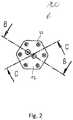
- Figure 2 shows a rear view of the in Figure 1 engine device shown.
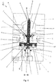
- FIG. 10 is a cross-sectional view of the engine device 100 taken along the line in FIG Figure 1 illustrated axis AA.
- Figure 4 shows the engine device in a schematic cross-sectional view along the axis BB of FIG Figure 2 and Figure 5 along the axis CC of the Figure 2 .
- the engine device 100 has an afterburning chamber 1 which is connected to a gas reservoir or a gas generator via gas inlet openings 27.
- the gas reservoir or the gas generator introduces gas into the afterburning chamber 1, which gas is accelerated through a gas outlet opening or engine nozzle 20 and discharged from the afterburning chamber 1 becomes.
- the discharged gas generates a thrust by means of which the flight direction of a missile having the propulsion unit can be changed.
- the thrust is varied by changing an effective cross section of the gas outlet opening 20.
- a nozzle needle 4 is arranged axially displaceably in the engine device 100, a first end region 28 of the nozzle needle 4 being at least partially insertable into the gas outlet opening 20, so that the effective Cross section of the gas outlet opening 20 is variable.
- the nozzle needle has a cylindrical section which tapers in the first end region 28.
- the end region 28 preferably tapers to a point.
- the end region can also be rounded or likewise cylindrical.
- the gas outlet opening 20 can preferably be completely closed by inserting the nozzle needle 4.
- the afterburning chamber 1 is separated from a control chamber 2 by a bulkhead 10. Seals 25, 26 are arranged between the bulkhead 10 and the housing. A seal retaining plate 15 is screwed to the bulkhead 10 by means of seal retaining screws 16, a nozzle needle seal 13 being fastened to the seal retaining plate 15. The nozzle needle 4 is inserted through the nozzle needle seal 13 and the seal holding plate 15 into the afterburning chamber 1 and is axially displaceable, the afterburning chamber 1 being sealed by the nozzle needle seal 13.
- the engine device 100 furthermore has a compensation chamber 3, the control chamber 2 being arranged in the axial direction between the afterburning chamber 1 and the compensation chamber 3.
- An intermediate chamber 30 is arranged between the compensation chamber 3 and the control chamber 2.
- the compensation chamber 3 and / or the afterburning chamber 1 are preferably arranged symmetrically around an axial displacement axis of the nozzle needle 4.
- the nozzle needle 4 has a piston device 5 at a second end region which is axially opposite to the first end region 28.
- the piston device 5 comprises a first section 29, which is arranged in the compensation chamber 3 so as to be axially displaceable and form-fitting.
- the piston device 5 further comprises a second section 7 which is arranged in the control chamber 2 in an axially displaceable and form-fitting manner.
- the first section 29 is via a piston screw 8 with the second section 7 of the Piston device 5 connected.
- a third section 6 faces away from the afterburning chamber 1 and is axially displaceable and arranged in a form-fitting manner in the intermediate chamber 30.
- piston seals 9 are enclosed in a radially outer direction, which prevent fluidic contact between the control chamber 2 and the intermediate chamber 30.
- Further seals 14 are arranged between the rear housing section 12 and a cylindrical protuberance of the third section 6 of the piston device 5, so that the cylindrical protuberance in the compensation chamber 3 can be moved in the axial direction and at the same time the compensation chamber 3 is sealed off from the intermediate chamber 30.
- the intermediate chamber 30 is fluidically connected to an ambient air via vent openings 21, so that a neutral ambient pressure prevails in the intermediate chamber 30 and the nozzle needle 4 can be displaced in the axial direction in the intermediate chamber 30 without any air in the intermediate chamber 30 exerting an axial force the nozzle needle 4 exerts.
- the afterburning chamber 1 is preferably fluidically connected to the compensation chamber 3.
- the compensation chamber 3 and the afterburning chamber 1 can be connected to the same gas reservoir or gas generator, or the afterburning chamber 1 and the compensation chamber 3 can be connected to one another via a fluid line or gas line.
- the piston device 5 has a sensor connection 17 which can be or is connected to a sensor device which can also be part of the engine device 100.
- the sensor device can be screwed to a screw hole 23 of the rear housing section 12 by means of screws and fastened thereto.
- the sensor device is designed to measure an axial position of the nozzle needle 4.
- the afterburning chamber 1 also has a connection 18 which can be or is connected to a pressure / temperature measuring transducer, which can also be part of the engine device 100.
- the pressure / temperature transducer is designed to measure a pressure or a temperature in the afterburning chamber 1.
- the control chamber 2 also has a connection 19 which can be or is connected to a pressure / temperature transducer which is connected to the pressure / temperature transducer connected to the connection 18 of the afterburning chamber 1 can be identical or different from this.
- the pressure / temperature transducer is designed to measure a pressure or a temperature in the control chamber 2 and can likewise be part of the engine device 100.
- a gas located in the compensation chamber 3 pressurizes the first section 29 of the piston device 5 in such a way that the nozzle needle 4 has an in Figure 5
- the axial compensating force F A drawn in the direction of the gas outlet opening 20 of the afterburning chamber 1 is experienced. Due to the air flow through the gas outlet opening 20 of the afterburning chamber 1, the first end region 28 of the nozzle needle 4 is also subjected to pressure so that an air force F L is exerted away from the gas outlet opening 20 on the nozzle needle 4.
- the compensation chamber is preferably dimensioned, i.e. a size and / or geometric shape of the compensation chamber is selected such that the compensation force F A when the nozzle needle is completely retracted, i.e. in a position in which the nozzle needle 4 is maximally far out of the gas outlet opening 20 of the Afterburning chamber 1 is moved out, greater than the air force F L. In this case, this creates an effective force in the direction of the gas outlet opening 20.
- the control chamber 2 has a gas opening 24, via which gas can be introduced or discharged into the control chamber 2.
- a control force F S can be generated on the nozzle needle 4, which is generated by the gas pressure of the gas in the control chamber 2 and points away from the gas outlet opening 20.
- the inflow and outflow of the gas into the control chamber 2 can take place through two 2/2-way valves or one 3/3-way valve.
- the engine device 100 preferably also has a control device (not shown) which is designed to adjust the axial position of the nozzle needle 4 by changing a gas pressure of a gas located in the control chamber 2.
- the control device is preferably connected to the sensor device and receives a current axial position of the nozzle needle 4 from the sensor device. Based on the current axial position of the nozzle needle 4, the control device increases or decreases the gas pressure of the gas in the control chamber 2 until the gas pressure of the Sensor device measured current axial position of a predetermined position corresponds.
- the control force F S which points away from the gas outlet opening 20, is increased, so that the nozzle needle 4 can be moved further out of the gas outlet opening 20 by increasing the gas pressure of the gas.
- control device can reduce the control force F S by reducing the gas pressure of the gas in the control chamber 2, so that the nozzle needle 4 is moved or inserted further into the gas outlet opening 20 due to the compensating force F A.
- the effective cross section of the gas outlet opening 20 is thereby reduced.
- the control device is thus designed to continuously change the axial position of the nozzle needle 4.
- control device can also be designed to set a pressure of a gas in the compensation chamber 3.
- the control device can preferably set both the gas pressure of the gas in the equalization chamber and the gas pressure of the gas in the control chamber 2.
- the order in which the compensation chamber 3, control chamber 2 and afterburning chamber 1 are arranged is also not limited to the embodiments shown.
- the compensation chamber 3 can be arranged between the control chamber 2 and the afterburning chamber 1.
Landscapes
- Engineering & Computer Science (AREA)
- Chemical & Material Sciences (AREA)
- Combustion & Propulsion (AREA)
- Mechanical Engineering (AREA)
- General Engineering & Computer Science (AREA)
- Testing Of Engines (AREA)
- Jet Pumps And Other Pumps (AREA)
- Output Control And Ontrol Of Special Type Engine (AREA)
Description
- Die vorliegende Erfindung betrifft eine Triebwerkvorrichtung eines Raketentriebwerks.
- Zur Raketenabwehr werden Abfangflugkörper mit den zu zerstörenden ballistischen Zielen zur Kollision gebracht, wobei die kinetische Energie, welche bei dem Zusammenstoß umgewandelt wird, das Ziel zerstört. Die Ziele selbst bewegen sich jedoch mit hohen Geschwindigkeiten und auf nur bedingt vorhersehbaren Flugbahnen, sodass eine hochagile Steuerung der Abfangflugkörper essentiell ist.
- Hierzu werden üblicherweise reaktive Querschub- und Lageregelungssysteme eingesetzt. Diese Systeme können durch diskrete Schubimpulse betrieben werden, wobei die Triebwerke an- bzw. ausgeschaltet werden. In diesem Fall wird der Schub lediglich zur Kurskorrektur eingesetzt. Darüber hinaus stehen kontinuierliche Schubsteuerungen zur Verfügung, welche eine genaue Einstellung des Schubes erlauben.
- Eine Möglichkeit, den Schub zu regulieren, besteht darin, eine Düsennadel, das heißt einen länglichen Körper, in eine Düsenöffnung hineinzuschieben bzw. aus dieser herauszuschieben. Hierdurch wird der effektive Querschnitt der Düse, das heißt der für das ausströmende Gas verfügbare Anteil des Querschnitts, verringert und dadurch der Schub verändert. Aus der Druckschrift
US 6 986 246 B2 ist eine derartige Triebwerkvorrichtung bekannt, wobei die Düsennadel mechanisch in axialer Richtung verschoben wird. - Die
US 6 227 247 B1 beschreibt ein Triebwerksventil mit einem zwischen einer geschlossenen und einer maximal offenen Position kontinuierlich positionierbaren Kolben. Der Kolben bewegt sich als Reaktion auf die Druckdifferenz zwischen dem Druck im Zwischenring und dem Druck hinter dem Kolben. Ein schwenkbares Klappenventil regelt diese Druckdifferenz. Wenn eine Änderung der Schubkraft erforderlich ist, wird die Position der Prallplatte geändert, was eine Änderung dieser Druckdifferenz bewirkt, die den Kolben so lange bewegt, bis das gewünschte Schubniveau erreicht ist.
Es ist eine Aufgabe der Erfindung, eine verbesserte Schubeinstellung zu ermöglichen. - Diese Aufgabe wird durch eine Triebwerkvorrichtung mit den Merkmalen des Patentanspruchs 1 gelöst. Vorteilhafte Ausführungsformen der Erfindung sind Gegenstand der abhängigen Patentansprüche.
- Die Erfindung betrifft demnach eine Triebwerkvorrichtung eines Raketentriebwerks, welche eine Nachbrennkammer umfasst, die eine Gaseinlassöffnung zum Einströmen eines Gases in die Nachbrennkammer aufweist, sowie eine Gasauslassöffnung bzw. Düse aufweist, welche zum Ausströmen des Gases aus der Nachbrennkammer ausgebildet ist. Die Triebwerkvorrichtung umfasst weiter eine mit Gas befüllbare Ausgleichskammer und eine mit Gas befüllbare Steuerkammer. Eine Düsennadel ist in axial verschiebbarer Weise derart angeordnet, dass ein erster Endbereich der Düsennadel zumindest teilweise in die Gasauslassöffnung einführbar ist. Ein zweiter Endbereich der Düsennadel weist eine Kolbeneinrichtung auf, wobei ein erster Abschnitt der Kolbeneinrichtung in der Ausgleichskammer angeordnet ist und durch ein in der Ausgleichskammer befindliches Gas mit Druck derart beaufschlagbar ist, dass die Düsennadel eine axiale Kraft in Richtung der Gasauslassöffnung erfährt. Ein zweiter Abschnitt der Kolbeneinrichtung ist in der Steuerkammer angeordnet und durch Einfüllen eines Gases in die Steuerkammer mit Druck derart beaufschlagbar, dass die Düsennadel eine axiale Kraft in Richtung von der Gasauslassöffnung weg erfährt. Die Nachbrennkammer ist von der Steuerkammer durch einen Schott getrennt. Die Steuerkammer weist eine Gasöffnung auf, über welche Gas in die Steuerkammer einleitbar bzw. ausleitbar ist. Die Kolbeneinrichtung ist in einer zwischen der Steuerkammer und der Ausgleichskammer angeordneten Zwischenkammer verschiebbar, wobei die Zwischenkammer fluidisch mit einer Umgebungsluft verbunden ist.
- In Abhängigkeit von den Gasdruckverhältnissen in den drei Kammern, das heißt der Ausgleichskammer, der Steuerkammer und der Nachbrennkammer, werden jeweilige axiale Kräfte auf die Düsennadel ausgeübt. Durch Einstellen der Drücke kann daher die Position der Düsennadel genau eingestellt werden. Durch die pneumatische Steuerung wird eine sehr kurze Stellzeit erreicht, so dass der effektive Querschnitt der Gasauslassöffnung der Nachbrennkammer extrem schnell variiert werden kann. Dadurch kann der Schub der Triebwerkvorrichtung präzise eingestellt werden.
- Gemäß einer bevorzugten Ausführungsform weist die Triebwerkvorrichtung eine Steuereinrichtung auf, die dazu ausgebildet ist, eine axiale Position der Düsennadel durch Verändern eines Gasdrucks eines in der Steuerkammer befindlichen Gases einzustellen. Durch Veränderung des Gasdrucks wird die axiale Kraft auf die Düsennadel verändert, so dass die Position der Düsennadel und damit auch der effektive Querschnitt der Gasauslassöffnung exakt eingestellt werden können.
- Gemäß einer bevorzugten Weiterbildung der Triebwerkvorrichtung ist die Steuereinrichtung darüber hinaus dazu ausgebildet, einen Gasdruck eines Gases in der Ausgleichskammer einzustellen. Dadurch kann sowohl die axiale Kraft auf die Düsennadel in Richtung der Gasauslassöffnung als auch von der Gasauslassöffnung weg eingestellt werden.
- Gemäß einer bevorzugten Ausführungsform weist die Triebwerkvorrichtung eine Sensoreinrichtung auf, die dazu ausgebildet ist, eine axiale Position der Düsennadel zu messen. Anhand der gemessenen Position kann beispielsweise die Steuereinrichtung den Gasdruck des Gases in der Steuerkammer und/oder Ausgleichskammer derart einstellen, dass die Düsennadel in eine vorgegebene axiale Position verschoben wird.
- Gemäß einer bevorzugten Weiterbildung der Triebwerkvorrichtung ist die Nachbrennkammer mit der Ausgleichskammer fluidisch verbunden. Somit entspricht der Druck in der Nachbrennkammer im Wesentlichen dem Druck in der Ausgleichskammer, abgesehen von dynamischen Fluktuationen aufgrund der Verschiebung der Düsennadel sowie der Strömungsverluste durch ein Überströmen von Gasmengen. Vorzugsweise ist die Nachbrennkammer hierbei derart ausgelegt, dass in dem Fall, in welchem die Steuerkammer gelüftet, das heißt nicht mit einem Gas beaufschlagt ist, eine axiale Kraft auf die Düsennadel in Richtung der Gasauslassöffnung größer ist als eine aufgrund der Strömung des Gases in der Nachbrennkammer auf die Düsennadel ausgeübte axiale Kraft von der Gasauslassöffnung weg. Die Steuerkammer dient dazu, eine Gegenkraft aufzubauen, welche die Düsennadel von der Gasauslassöffnung weg verschiebt. Da hierzu nur die Druckdifferenz erforderlich ist, wird die Düsennadel bereits durch Beaufschlagen mit geringem Gasdruck axial verschoben, so dass eine geringe Änderung des Gasdruckes zur Einstellung der exakten axialen Position der Düsennadel ausreicht. Dadurch wird die Stellzeit sehr kurz gehalten.
- Gemäß einer bevorzugten Ausführungsform der Triebwerkvorrichtung ist die Steuerkammer in axialer Richtung zwischen der Ausgleichskammer und der Nachbrennkammer angeordnet. Die axiale Richtung entspricht hierbei der axialen Verschiebungsrichtung der Düsennadel.
- Gemäß einer Weiterbildung der Triebwerkvorrichtung sind die Ausgleichskammer und/oder die Nachbrennkammer symmetrisch um eine axiale Verschiebungsachse der Düsennadel herum angeordnet.
- Gemäß einer Weiterbildung der Triebwerkvorrichtung ist die Gasauslassöffnung durch Einführen der Düsennadel vollständig verschließbar. Der von der Triebwerkvorrichtung bereitgestellte Schub kann somit kontinuierlich zwischen Null und einem maximalen vorgegebenen Wert variiert werden, wobei der maximale Wert einer Position entspricht, in welcher die Düsennadel vollständig aus der Gasauslassöffnung heraus verschoben ist.
- Im Folgenden wird die Erfindung unter Bezugnahme auf die Figuren der Zeichnungen erläutert. Von den Figuren zeigen:
- Fig. 1
- eine schematische Seitenansicht einer Triebwerkvorrichtung gemäß einer Ausführungsform der Erfindung;
- Fig. 2
- eine schematische Rückansicht der in
Fig. 1 gezeigten Triebwerkvorrichtung; - Fig. 3
- eine schematische Querschnittsansicht der Triebwerkvorrichtung, welche sich bei einem Schnitt entlang der in
Fig. 1 gezeigten Achse A-A ergibt; - Fig. 4
- eine schematische Querschnittsansicht der Triebwerkvorrichtung, welche sich bei einem Schnitt entlang der in
Fig. 2 gezeigten Achse B-B ergibt; und - Fig. 5
- eine schematische Querschnittsansicht der Triebwerkvorrichtung, welche sich bei einem Schnitt entlang der in
Fig. 2 gezeigten Achse C-C ergibt. - Sofern sinnvoll lassen sich die beschriebenen Ausgestaltungen und Weiterbildungen beliebig miteinander kombinieren. Weitere mögliche Ausgestaltungen, Weiterbildungen und Implementierungen der Erfindung umfassen auch nicht explizit genannte Kombinationen von zuvor oder im Folgenden bezüglich der Ausführungsbeispiele beschriebenen Merkmale der Erfindung.
- Die beiliegenden Zeichnungen sollen ein weiteres Verständnis der Ausführungsformen der Erfindung vermitteln. Sie veranschaulichen Ausführungsformen und dienen im Zusammenhang mit der Beschreibung der Erklärung von Prinzipien und Konzepten der Erfindung. Andere Ausführungsformen und viele der genannten Vorteile ergeben sich im Hinblick auf die Zeichnungen. Die Elemente der Zeichnungen sind nicht notwendigerweise maßstabsgetreu zueinander gezeigt. Gleiche Bezugszeichen bezeichnen dabei gleiche oder ähnlich wirkende Komponenten.
- In
Figur 1 ist eine schematische Seitenansicht einer Triebwerkvorrichtung 100 gezeigt, welche ein Gehäuse mit einem vorderen Gehäuseabschnitt 11 und einem hinteren Gehäuseabschnitt 12 aufweist. -
Figur 2 zeigt eine Rückansicht der inFigur 1 gezeigten Triebwerkvorrichtung. - In
Figur 3 ist eine Querschnittsansicht der Triebwerkvorrichtung 100 entlang der inFigur 1 eingezeichneten Achse A-A illustriert. -
Figur 4 zeigt die Triebwerkvorrichtung in einer schematischen Querschnittsansicht entlang der Achse B-B derFigur 2 undFigur 5 entlang der Achse C-C derFigur 2 . - Die Triebwerkvorrichtung 100 weist eine Nachbrennkammer 1 auf, welche über Gaseinlassöffnungen 27 mit einem Gasreservoir oder einem Gasgenerator verbunden ist. Das Gasreservoir oder der Gasgenerator leitet Gas in die Nachbrennkammer 1 ein, welches durch eine Gasauslassöffnung bzw. Triebwerksdüse 20 beschleunigt und aus der Nachbrennkammer 1 ausgeleitet wird. Das ausgeleitete Gas erzeugt einen Schub, über welchen die Flugrichtung eines die Triebwerkvorrichtung aufweisenden Flugkörpers verändert werden kann.
- Die Variation des Schubs erfolgt hierbei über eine Änderung eines effektiven Querschnitts der Gasauslassöffnung 20. Hierzu ist eine Düsennadel 4 axial verschiebbar in der Triebwerkvorrichtung 100 angeordnet, wobei ein erster Endbereich 28 der Düsennadel 4 zumindest teilweise in die Gasauslassöffnung 20 einführbar ist, so dass der effektive Querschnitt der Gasauslassöffnung 20 variierbar ist. Die Düsennadel weist hierzu einen zylinderförmigen Abschnitt auf, welcher sich im ersten Endbereich 28 verjüngt. Vorzugsweise läuft der Endbereich 28 spitz zu. Der Endbereich kann jedoch gemäß weiteren Ausführungsformen auch abgerundet oder ebenfalls zylinderförmig sein. Die Gasauslassöffnung 20 ist vorzugsweise durch Einführen der Düsennadel 4 vollständig verschließbar.
- Die Nachbrennkammer 1 ist über einen Schott 10 von einer Steuerkammer 2 getrennt. Zwischen dem Schott 10 und dem Gehäuse sind Dichtungen 25, 26 angeordnet. Eine Dichtungshalteplatte 15 ist mittels Dichtungshalteschrauben 16 mit dem Schott 10 verschraubt, wobei eine Düsennadeldichtung 13 an der Dichtungshalteplatte 15 befestigt ist. Die Düsennadel 4 ist durch die Düsennadeldichtung 13 und die Dichtungshalteplatte 15 hindurch in die Nachbrennkammer 1 eingeführt und axial verschiebbar, wobei die Nachbrennkammer 1 durch die Düsennadeldichtung 13 abgedichtet ist.
- Die Triebwerkvorrichtung 100 weist weiter eine Ausgleichskammer 3 auf, wobei die Steuerkammer 2 in axialer Richtung zwischen der Nachbrennkammer 1 und der Ausgleichskammer 3 angeordnet ist. Zwischen der Ausgleichskammer 3 und der Steuerkammer 2 ist eine Zwischenkammer 30 angeordnet. Vorzugsweise sind die Ausgleichskammer 3 und/oder die Nachbrennkammer 1 symmetrisch um eine axiale Verschiebungsachse der Düsennadel 4 herum angeordnet.
- Die Düsennadel 4 weist an einem zweiten Endbereich, welcher dem ersten Endbereich 28 axial entgegengesetzt ist, eine Kolbeneinrichtung 5 auf. Die Kolbeneinrichtung 5 umfasst einen ersten Abschnitt 29, welcher in der Ausgleichskammer 3 axial verschiebbar und formschlüssig angeordnet ist. Weiter umfasst die Kolbeneinrichtung 5 einen zweiten Abschnitt 7, welcher axial verschiebbar und formschlüssig in der Steuerkammer 2 angeordnet ist. Der erste Abschnitt 29 ist über eine Kolbenschraube 8 mit dem zweiten Abschnitt 7 der Kolbeneinrichtung 5 verbunden. Ein dritter Abschnitt 6 ist von der Nachbrennkammer 1 abgewandt und axial verschiebbar sowie formschlüssig in der Zwischenkammer 30 angeordnet. Zwischen dem zweiten Abschnitt 7 und dem dritten Abschnitt 6 der Kolbeneinrichtung 5 sind in einer radial äußeren Richtung Kolbendichtungen 9 eingeschlossen, welche einen fluidischen Kontakt der Steuerkammer 2 mit der Zwischenkammer 30 verhindern. Weitere Dichtungen 14 sind zwischen dem hinteren Gehäuseabschnitt 12 und einer zylindrischen Ausstülpung des dritten Abschnitts 6 der Kolbeneinrichtung 5 angeordnet, so dass die zylindrische Ausstülpung in der Ausgleichskammer 3 in axialer Richtung verschiebbar ist und gleichzeitig die Ausgleichskammer 3 gegenüber der Zwischenkammer 30 abgedichtet ist.
- Die Zwischenkammer 30 ist über Entlüftungsöffnungen 21 fluidisch mit einer Umgebungsluft verbunden, so dass in der Zwischenkammer 30 ein neutraler Umgebungsdruck vorherrscht und die Düsennadel 4 in axialer Richtung in der Zwischenkammer 30 verschiebbar ist, ohne dass eine in der Zwischenkammer 30 befindliche Luft eine axiale Kraft auf die Düsennadel 4 ausübt.
- Vorzugsweise ist die Nachbrennkammer 1 mit der Ausgleichskammer 3 fluidisch verbunden. So können die Ausgleichskammer 3 und die Nachbrennkammer 1 mit demselben Gasreservoir oder Gasgenerator verbunden sein oder die Nachbrennkammer 1 und die Ausgleichskammer 3 können über eine Fluidleitung bzw. Gasleitung miteinander verbunden sein.
- Die Kolbeneinrichtung 5 weist einen Sensoranschluss 17 auf, welcher mit einer Sensoreinrichtung verbindbar bzw. verbunden ist, welche ebenfalls Teil der Triebwerkvorrichtung 100 sein kann. Die Sensoreinrichtung kann mittels Schrauben an einem Schraubenloch 23 des hinteren Gehäuseabschnittes 12 verschraubt und daran befestigt werden. Die Sensoreinrichtung ist dazu ausgebildet, eine axiale Position der Düsennadel 4 zu messen.
- Weiter weist die Nachbrennkammer 1 einen Anschluss 18 auf, welcher mit einem Druck-/Temperaturmesswandler verbindbar bzw. verbunden ist, welcher ebenfalls Teil der Triebwerkvorrichtung 100 sein kann. Der Druck-/Temperaturmesswandler ist dazu ausgebildet, einen Druck bzw. eine Temperatur in der Nachbrennkammer 1 zu messen. Weiter weist die Steuerkammer 2 einen Anschluss 19 auf, welcher mit einem Druck-/Temperaturmesswandler verbindbar oder verbunden ist, welcher mit dem an den Anschluss 18 der Nachbrennkammer 1 angeschlossenen Druck-/Temperaturmesswandler identisch sein kann oder von diesem verschieden sein kann. Der Druck-/Temperaturmesswandler ist dazu ausgebildet, einen Druck bzw. eine Temperatur in der Steuerkammer 2 zu messen und kann ebenfalls Teil der Triebwerkvorrichtung 100 sein.
- Ein in der Ausgleichskammer 3 befindliches Gas beaufschlagt den ersten Abschnitt 29 der Kolbeneinrichtung 5 derart mit Druck, dass die Düsennadel 4 eine in
Figur 5 eingezeichnete axiale Ausgleichskraft FA in Richtung der Gasauslassöffnung 20 der Nachbrennkammer 1 erfährt. Aufgrund des Luftstroms durch die Gasauslassöffnung 20 der Nachbrennkammer 1 wird der erste Endbereich 28 der Düsennadel 4 ebenfalls mit Druck beaufschlagt, so dass eine Luftkraft FL von der Gasauslassöffnung 20 weg auf die Düsennadel 4 ausgeübt wird. Die Ausgleichskammer ist vorzugsweise derart dimensioniert, das heißt eine Größe und/oder geometrische Form der Ausgleichskammer ist derart gewählt, dass die Ausgleichskraft FA bei vollständig zurückgefahrener Düsennadel, das heißt in einer Position, in welcher die Düsennadel 4 maximal weit aus der Gasauslassöffnung 20 der Nachbrennkammer 1 herausbewegt ist, größer als die Luftkraft FL ist. Dadurch entsteht in diesem Fall eine effektive Kraft in Richtung der Gasauslassöffnung 20. - Die Steuerkammer 2 weist eine Gasöffnung 24 auf, über welche Gas in die Steuerkammer 2 einleitbar bzw. ausleitbar ist. Durch Einleiten eines Gases über die Gasöffnung 24 in die Steuerkammer 2 kann eine Steuerkraft FS auf die Düsennadel 4 erzeugt werden, welche durch den Gasdruck des Gases in der Steuerkammer 2 entsteht und von der Gasauslassöffnung 20 weg zeigt. Der Zu- und Abstrom des Gases in die Steuerkammer 2 kann durch zwei 2/2-Wege-Ventil oder ein 3/3-Wege-Ventil erfolgen.
- Die Triebwerkvorrichtung 100 weist vorzugsweise weiter eine (nicht gezeigte) Steuereinrichtung auf, welche dazu ausgebildet ist, die axiale Position der Düsennadel 4 durch Verändern eines Gasdrucks eines in der Steuerkammer 2 befindlichen Gases einzustellen. Vorzugsweise ist die Steuereinrichtung mit der Sensoreinrichtung verbunden und empfängt von der Sensoreinrichtung eine aktuelle axiale Position der Düsennadel 4. Basierend auf der aktuellen axialen Position der Düsennadel 4 erhöht oder erniedrigt die Steuereinrichtung den Gasdruck des in der Steuerkammer 2 befindlichen Gases solange, bis die von der Sensoreinrichtung gemessene aktuelle axiale Position einer vorgegebenen Position entspricht. Durch Erhöhen des Gasdrucks des in der Steuerkammer 2 befindlichen Gases wird die Steuerkraft FS, welche von der Gasauslassöffnung 20 weg zeigt, erhöht, so dass durch Erhöhen des Gasdrucks des Gases die Düsennadel 4 weiter aus der Gasauslassöffnung 20 heraus verschoben werden kann. Umgekehrt kann die Steuereinrichtung durch Verringern des Gasdrucks des in der Steuerkammer 2 befindlichen Gases die Steuerkraft FS verringern, so dass die Düsennadel 4 aufgrund der Ausgleichskraft FA weiter in die Gasauslassöffnung 20 hinein bewegt bzw. eingeführt wird. Der effektive Querschnitt der Gasauslassöffnung 20 wird dadurch verringert. Die Steuereinrichtung ist somit dazu ausgelegt, die axiale Position der Düsennadel 4 kontinuierlich zu verändern.
- Die Erfindung ist nicht auf die gezeigten Ausführungsbeispiele beschränkt. So kann gemäß weiteren Ausführungsformen die Steuereinrichtung darüber hinaus dazu ausgebildet sein, einen Druck eines Gases in der Ausgleichskammer 3 einzustellen. Vorzugsweise kann die Steuereinrichtung sowohl den Gasdruck des Gases in der Ausgleichskammer als auch den Gasdruck des Gases in der Steuerkammer 2 einstellen. Auch die Reihenfolge der Anordnung von Ausgleichskammer 3, Steuerkammer 2 und Nachbrennkammer 1 ist nicht auf die gezeigten Ausführungsformen beschränkt. So kann gemäß weiterer Ausführungsformen die Ausgleichskammer 3 zwischen der Steuerkammer 2 und der Nachbrennkammer 1 angeordnet sein.
-
- 1
- Nachbrennkammer
- 2
- Steuerkammer
- 3
- Ausgleichkammer
- 4
- Düsennadel
- 5
- Kolbeneinrichtung
- 6
- dritter Abschnitt der Kolbeneinrichtung
- 7
- zweiter Abschnitt der Kolbeneinrichtung
- 8
- Kolbenschraube
- 9
- Kolbendichtung
- 10
- Schott
- 11
- vorderer Gehäuseabschnitt
- 12
- hinterer Gehäuseabschnitt
- 13
- Düsennadeldichtung
- 14
- Dichtung
- 15
- Dichtungshalteplatte
- 16
- Dichtungshalteschraube
- 17
- Sensoranschluss
- 18
- Nachbrennkammer-Anschluss an Druck-/Temperaturmesswandler
- 19
- Steuerkammer-Anschluss an Druck-/Temperaturmesswandler
- 20
- Gasauslassöffnung
- 21
- Lüftungsöffnungen
- 22
- Gehäuseschrauben
- 23
- Schraubloch
- 24
- Gasöffnung
- 25
- Dichtung
- 26
- Dichtung
- 27
- Gaseinlassöffnungen
- 28
- erster Endbereich der Düsennadel
- 29
- erster Abschnitt der Kolbeneinrichtung
- 30
- Zwischenkammer
- 100
- Triebwerkvorrichtung
Claims (8)
- Triebwerkvorrichtung (100) eines Raketentriebwerks, aufweisend:eine Nachbrennkammer (1) mit einer Gaseinlassöffnung (27) zum Einströmen eines Gases in die Nachbrennkammer (1) und einer Gasauslassöffnung (20) zum Ausströmen des Gases;eine mit Gas befüllbare Ausgleichskammer (3);eine mit Gas befüllbare Steuerkammer (2); undeine Düsennadel (4), welche axial verschiebbar derart angeordnet ist, dass ein erster Endbereich (28) der Düsennadel (4) zumindest teilweise in die Gasauslassöffnung (20) einführbar ist;wobei die Düsennadel (4) an einem zweiten Endbereich eine Kolbeneinrichtung (5) aufweist, wobei ein erster Abschnitt (29) der Kolbeneinrichtung (5) in der Ausgleichskammer (3) angeordnet ist und durch ein in der Ausgleichskammer (3) befindliches Gas mit Druck derart beaufschlagbar ist, dass die Düsennadel (4) eine axiale Kraft in Richtung der Gasauslassöffnung (20) erfährt, wobei ein zweiter Abschnitt (7) der Kolbeneinrichtung (5) in der Steuerkammer (2) angeordnet ist und durch Einfüllen eines Gases in die Steuerkammer (2) mit Druck derart beaufschlagbar ist, dass die Düsennadel (4) eine axiale Kraft in Richtung von der Gasauslassöffnung (20) weg erfährt;wobei die Nachbrennkammer (1) von der Steuerkammer (2) durch einen Schott (10) getrennt ist;wobei die Steuerkammer (2) eine Gasöffnung (24) aufweist, über welche Gas in die Steuerkammer (2) einleitbar bzw. ausleitbar ist wobei die Kolbeneinrichtung (5) in einer zwischen der Steuerkammer (2) und der Ausgleichskammer (3) angeordneten Zwischenkammer (30) verschiebbar ist, wobei die Zwischenkammer (30) fluidisch mit einer Umgebungsluft verbunden ist.
- Triebwerkvorrichtung (100) nach Anspruch 1, mit einer Steuereinrichtung, welche dazu ausgebildet ist, eine axiale Position der Düsennadel (4) durch Verändern eines Gasdrucks eines in der Steuerkammer (2) befindlichen Gases einzustellen.
- Triebwerkvorrichtung (100) nach Anspruch 2, wobei die Steuereinrichtung weiter dazu ausgebildet ist, einen Gasdruck eines Gases in der Ausgleichskammer (3) einzustellen.
- Triebwerkvorrichtung (100) nach einem der vorangehenden Ansprüche, mit einer Sensoreinrichtung, welche dazu ausgebildet ist, eine axiale Position der Düsennadel (4) zu messen.
- Triebwerkvorrichtung (100) nach einem der vorangehenden Ansprüche, wobei die Nachbrennkammer (1) mit der Ausgleichskammer (3) fluidisch verbunden ist.
- Triebwerkvorrichtung (100) nach einem der vorangehenden Ansprüche, wobei die Steuerkammer (2) in axialer Richtung zwischen der Ausgleichskammer (3) und der Nachbrennkammer (1) angeordnet ist.
- Triebwerkvorrichtung (100) nach einem der vorangehenden Ansprüche, wobei die Ausgleichskammer (3) und/oder die Nachbrennkammer (1) symmetrisch um eine axiale Verschiebungsachse der Düsennadel herum angeordnet sind.
- Triebwerkvorrichtung (100) nach einem der vorangehenden Ansprüche, wobei die Gasauslassöffnung (20) durch Einführen der Düsennadel (4) vollständig verschließbar ist.
Applications Claiming Priority (1)
| Application Number | Priority Date | Filing Date | Title |
|---|---|---|---|
| DE102016217104.6A DE102016217104A1 (de) | 2016-09-08 | 2016-09-08 | Triebwerkvorrichtung eines Raketentriebwerks |
Publications (2)
| Publication Number | Publication Date |
|---|---|
| EP3293389A1 EP3293389A1 (de) | 2018-03-14 |
| EP3293389B1 true EP3293389B1 (de) | 2021-02-24 |
Family
ID=59702619
Family Applications (1)
| Application Number | Title | Priority Date | Filing Date |
|---|---|---|---|
| EP17187938.0A Active EP3293389B1 (de) | 2016-09-08 | 2017-08-25 | Triebwerkvorrichtung eines raketentriebwerks |
Country Status (3)
| Country | Link |
|---|---|
| EP (1) | EP3293389B1 (de) |
| DE (1) | DE102016217104A1 (de) |
| ES (1) | ES2857249T3 (de) |
Families Citing this family (1)
| Publication number | Priority date | Publication date | Assignee | Title |
|---|---|---|---|---|
| CN110849519A (zh) * | 2019-10-14 | 2020-02-28 | 中国北方发动机研究所(天津) | 一种轴向力气动平衡装置及测功机装置 |
Family Cites Families (2)
| Publication number | Priority date | Publication date | Assignee | Title |
|---|---|---|---|---|
| US6227247B1 (en) | 2000-02-10 | 2001-05-08 | Honeywell International | Position driven hot gas proportional thruster valve |
| US6986246B2 (en) | 2002-05-21 | 2006-01-17 | Mitsubishi Heavy Industries, Ltd. | Side thruster valve and side thruster device |
-
2016
- 2016-09-08 DE DE102016217104.6A patent/DE102016217104A1/de active Granted
-
2017
- 2017-08-25 ES ES17187938T patent/ES2857249T3/es active Active
- 2017-08-25 EP EP17187938.0A patent/EP3293389B1/de active Active
Non-Patent Citations (1)
| Title |
|---|
| None * |
Also Published As
| Publication number | Publication date |
|---|---|
| ES2857249T3 (es) | 2021-09-28 |
| DE102016217104A1 (de) | 2018-03-08 |
| EP3293389A1 (de) | 2018-03-14 |
Similar Documents
| Publication | Publication Date | Title |
|---|---|---|
| DE2815087C2 (de) | Lenkvorrichtung für ein Geschoß | |
| EP2209998B1 (de) | Vorgesteuerter wegeschieber, insbesondere zur steuerung eines stellzylinders einer turbomaschine | |
| DE68927060T2 (de) | Mittels Schubvektorsteuerung arbeitende Lenkvorrichtung für einen Flugkörper | |
| DE2743371A1 (de) | Kombiniertes heissgas-servosteuersystem fuer ruder und rueckstoss bei flugkoerpern | |
| DE3149735A1 (de) | Staustrahltriebwerk-geschoss und verfahren, das dieses einer ballistischen flugbahn folgen laesst | |
| DE2616209A1 (de) | Kurzbahngeschoss fuer uebungsmunition | |
| DE102010032750B4 (de) | Pneumatikantrieb | |
| DE1172901B (de) | UEberschall-Lufteinlass mit innerer Verdichtung | |
| EP3293389B1 (de) | Triebwerkvorrichtung eines raketentriebwerks | |
| DE102007028143B4 (de) | Verfahren und Einrichtung zum Verstellen eines Funktionselementes in Abhängigkeit von der Strömungsgeschwindigkeit eines strömenden Mediums | |
| DE3441534A1 (de) | Lageranordnung fuer das ruderblatt eines flugkoerpers | |
| EP0894299A1 (de) | Vorgesteuertes 3-wege-druckregelventil | |
| EP0222057B1 (de) | Überdruckventil für einen pyrotechnischen Gasgenerator | |
| EP3318782A1 (de) | Stellvorrichtung | |
| DE2856286C2 (de) | Mit Überschallgeschwindigkeit fliegendes Geschoß | |
| DE2846372A1 (de) | Verfahren und vorrichtung zur steigerung der treffgenauigkeit von geschossen | |
| DE102024107878A1 (de) | Durchstoßvorrichtung zum Durchstoßen einer Wandstruktur | |
| DE19736297C2 (de) | Hydrodynamischer Drehmomentwandler mit einem Drosselelement | |
| DE3808655C2 (de) | Kanone mit Nachbeschleunigungsrohr und Projektil | |
| DE102004045855B4 (de) | Steuer- und/oder Antriebseinrichtung für einen Flugkörper | |
| DE2454584A1 (de) | Rohrfoermiges geschoss | |
| EP2734805A1 (de) | Patronierte munition | |
| DE1673369B2 (de) | Hydraulisch betaetigter fliehkraftregler | |
| EP0227854B1 (de) | Druckmindervorrichtung | |
| DE2744790A1 (de) | Uebungsflugkoerper, insbesondere uebungsgeschoss |
Legal Events
| Date | Code | Title | Description |
|---|---|---|---|
| PUAI | Public reference made under article 153(3) epc to a published international application that has entered the european phase |
Free format text: ORIGINAL CODE: 0009012 |
|
| STAA | Information on the status of an ep patent application or granted ep patent |
Free format text: STATUS: THE APPLICATION HAS BEEN PUBLISHED |
|
| AK | Designated contracting states |
Kind code of ref document: A1 Designated state(s): AL AT BE BG CH CY CZ DE DK EE ES FI FR GB GR HR HU IE IS IT LI LT LU LV MC MK MT NL NO PL PT RO RS SE SI SK SM TR |
|
| AX | Request for extension of the european patent |
Extension state: BA ME |
|
| STAA | Information on the status of an ep patent application or granted ep patent |
Free format text: STATUS: REQUEST FOR EXAMINATION WAS MADE |
|
| 17P | Request for examination filed |
Effective date: 20180824 |
|
| RBV | Designated contracting states (corrected) |
Designated state(s): AL AT BE BG CH CY CZ DE DK EE ES FI FR GB GR HR HU IE IS IT LI LT LU LV MC MK MT NL NO PL PT RO RS SE SI SK SM TR |
|
| STAA | Information on the status of an ep patent application or granted ep patent |
Free format text: STATUS: EXAMINATION IS IN PROGRESS |
|
| 17Q | First examination report despatched |
Effective date: 20190104 |
|
| GRAP | Despatch of communication of intention to grant a patent |
Free format text: ORIGINAL CODE: EPIDOSNIGR1 |
|
| STAA | Information on the status of an ep patent application or granted ep patent |
Free format text: STATUS: GRANT OF PATENT IS INTENDED |
|
| INTG | Intention to grant announced |
Effective date: 20201013 |
|
| GRAS | Grant fee paid |
Free format text: ORIGINAL CODE: EPIDOSNIGR3 |
|
| GRAA | (expected) grant |
Free format text: ORIGINAL CODE: 0009210 |
|
| STAA | Information on the status of an ep patent application or granted ep patent |
Free format text: STATUS: THE PATENT HAS BEEN GRANTED |
|
| AK | Designated contracting states |
Kind code of ref document: B1 Designated state(s): AL AT BE BG CH CY CZ DE DK EE ES FI FR GB GR HR HU IE IS IT LI LT LU LV MC MK MT NL NO PL PT RO RS SE SI SK SM TR |
|
| REG | Reference to a national code |
Ref country code: CH Ref legal event code: EP |
|
| REG | Reference to a national code |
Ref country code: DE Ref legal event code: R096 Ref document number: 502017009445 Country of ref document: DE |
|
| REG | Reference to a national code |
Ref country code: AT Ref legal event code: REF Ref document number: 1364734 Country of ref document: AT Kind code of ref document: T Effective date: 20210315 |
|
| REG | Reference to a national code |
Ref country code: IE Ref legal event code: FG4D Free format text: LANGUAGE OF EP DOCUMENT: GERMAN |
|
| REG | Reference to a national code |
Ref country code: LT Ref legal event code: MG9D |
|
| REG | Reference to a national code |
Ref country code: NL Ref legal event code: MP Effective date: 20210224 |
|
| PG25 | Lapsed in a contracting state [announced via postgrant information from national office to epo] |
Ref country code: GR Free format text: LAPSE BECAUSE OF FAILURE TO SUBMIT A TRANSLATION OF THE DESCRIPTION OR TO PAY THE FEE WITHIN THE PRESCRIBED TIME-LIMIT Effective date: 20210525 Ref country code: HR Free format text: LAPSE BECAUSE OF FAILURE TO SUBMIT A TRANSLATION OF THE DESCRIPTION OR TO PAY THE FEE WITHIN THE PRESCRIBED TIME-LIMIT Effective date: 20210224 Ref country code: FI Free format text: LAPSE BECAUSE OF FAILURE TO SUBMIT A TRANSLATION OF THE DESCRIPTION OR TO PAY THE FEE WITHIN THE PRESCRIBED TIME-LIMIT Effective date: 20210224 Ref country code: NO Free format text: LAPSE BECAUSE OF FAILURE TO SUBMIT A TRANSLATION OF THE DESCRIPTION OR TO PAY THE FEE WITHIN THE PRESCRIBED TIME-LIMIT Effective date: 20210524 Ref country code: PT Free format text: LAPSE BECAUSE OF FAILURE TO SUBMIT A TRANSLATION OF THE DESCRIPTION OR TO PAY THE FEE WITHIN THE PRESCRIBED TIME-LIMIT Effective date: 20210624 Ref country code: LT Free format text: LAPSE BECAUSE OF FAILURE TO SUBMIT A TRANSLATION OF THE DESCRIPTION OR TO PAY THE FEE WITHIN THE PRESCRIBED TIME-LIMIT Effective date: 20210224 Ref country code: BG Free format text: LAPSE BECAUSE OF FAILURE TO SUBMIT A TRANSLATION OF THE DESCRIPTION OR TO PAY THE FEE WITHIN THE PRESCRIBED TIME-LIMIT Effective date: 20210524 |
|
| PG25 | Lapsed in a contracting state [announced via postgrant information from national office to epo] |
Ref country code: LV Free format text: LAPSE BECAUSE OF FAILURE TO SUBMIT A TRANSLATION OF THE DESCRIPTION OR TO PAY THE FEE WITHIN THE PRESCRIBED TIME-LIMIT Effective date: 20210224 Ref country code: PL Free format text: LAPSE BECAUSE OF FAILURE TO SUBMIT A TRANSLATION OF THE DESCRIPTION OR TO PAY THE FEE WITHIN THE PRESCRIBED TIME-LIMIT Effective date: 20210224 Ref country code: RS Free format text: LAPSE BECAUSE OF FAILURE TO SUBMIT A TRANSLATION OF THE DESCRIPTION OR TO PAY THE FEE WITHIN THE PRESCRIBED TIME-LIMIT Effective date: 20210224 Ref country code: NL Free format text: LAPSE BECAUSE OF FAILURE TO SUBMIT A TRANSLATION OF THE DESCRIPTION OR TO PAY THE FEE WITHIN THE PRESCRIBED TIME-LIMIT Effective date: 20210224 Ref country code: SE Free format text: LAPSE BECAUSE OF FAILURE TO SUBMIT A TRANSLATION OF THE DESCRIPTION OR TO PAY THE FEE WITHIN THE PRESCRIBED TIME-LIMIT Effective date: 20210224 |
|
| REG | Reference to a national code |
Ref country code: ES Ref legal event code: FG2A Ref document number: 2857249 Country of ref document: ES Kind code of ref document: T3 Effective date: 20210928 |
|
| PG25 | Lapsed in a contracting state [announced via postgrant information from national office to epo] |
Ref country code: IS Free format text: LAPSE BECAUSE OF FAILURE TO SUBMIT A TRANSLATION OF THE DESCRIPTION OR TO PAY THE FEE WITHIN THE PRESCRIBED TIME-LIMIT Effective date: 20210624 |
|
| PG25 | Lapsed in a contracting state [announced via postgrant information from national office to epo] |
Ref country code: SM Free format text: LAPSE BECAUSE OF FAILURE TO SUBMIT A TRANSLATION OF THE DESCRIPTION OR TO PAY THE FEE WITHIN THE PRESCRIBED TIME-LIMIT Effective date: 20210224 Ref country code: CZ Free format text: LAPSE BECAUSE OF FAILURE TO SUBMIT A TRANSLATION OF THE DESCRIPTION OR TO PAY THE FEE WITHIN THE PRESCRIBED TIME-LIMIT Effective date: 20210224 Ref country code: EE Free format text: LAPSE BECAUSE OF FAILURE TO SUBMIT A TRANSLATION OF THE DESCRIPTION OR TO PAY THE FEE WITHIN THE PRESCRIBED TIME-LIMIT Effective date: 20210224 |
|
| REG | Reference to a national code |
Ref country code: DE Ref legal event code: R097 Ref document number: 502017009445 Country of ref document: DE |
|
| PG25 | Lapsed in a contracting state [announced via postgrant information from national office to epo] |
Ref country code: DK Free format text: LAPSE BECAUSE OF FAILURE TO SUBMIT A TRANSLATION OF THE DESCRIPTION OR TO PAY THE FEE WITHIN THE PRESCRIBED TIME-LIMIT Effective date: 20210224 Ref country code: RO Free format text: LAPSE BECAUSE OF FAILURE TO SUBMIT A TRANSLATION OF THE DESCRIPTION OR TO PAY THE FEE WITHIN THE PRESCRIBED TIME-LIMIT Effective date: 20210224 Ref country code: SK Free format text: LAPSE BECAUSE OF FAILURE TO SUBMIT A TRANSLATION OF THE DESCRIPTION OR TO PAY THE FEE WITHIN THE PRESCRIBED TIME-LIMIT Effective date: 20210224 |
|
| PLBE | No opposition filed within time limit |
Free format text: ORIGINAL CODE: 0009261 |
|
| STAA | Information on the status of an ep patent application or granted ep patent |
Free format text: STATUS: NO OPPOSITION FILED WITHIN TIME LIMIT |
|
| PG25 | Lapsed in a contracting state [announced via postgrant information from national office to epo] |
Ref country code: AL Free format text: LAPSE BECAUSE OF FAILURE TO SUBMIT A TRANSLATION OF THE DESCRIPTION OR TO PAY THE FEE WITHIN THE PRESCRIBED TIME-LIMIT Effective date: 20210224 |
|
| 26N | No opposition filed |
Effective date: 20211125 |
|
| PG25 | Lapsed in a contracting state [announced via postgrant information from national office to epo] |
Ref country code: SI Free format text: LAPSE BECAUSE OF FAILURE TO SUBMIT A TRANSLATION OF THE DESCRIPTION OR TO PAY THE FEE WITHIN THE PRESCRIBED TIME-LIMIT Effective date: 20210224 |
|
| REG | Reference to a national code |
Ref country code: CH Ref legal event code: PL |
|
| PG25 | Lapsed in a contracting state [announced via postgrant information from national office to epo] |
Ref country code: MC Free format text: LAPSE BECAUSE OF FAILURE TO SUBMIT A TRANSLATION OF THE DESCRIPTION OR TO PAY THE FEE WITHIN THE PRESCRIBED TIME-LIMIT Effective date: 20210224 |
|
| REG | Reference to a national code |
Ref country code: BE Ref legal event code: MM Effective date: 20210831 |
|
| PG25 | Lapsed in a contracting state [announced via postgrant information from national office to epo] |
Ref country code: LI Free format text: LAPSE BECAUSE OF NON-PAYMENT OF DUE FEES Effective date: 20210831 Ref country code: CH Free format text: LAPSE BECAUSE OF NON-PAYMENT OF DUE FEES Effective date: 20210831 |
|
| PG25 | Lapsed in a contracting state [announced via postgrant information from national office to epo] |
Ref country code: IS Free format text: LAPSE BECAUSE OF FAILURE TO SUBMIT A TRANSLATION OF THE DESCRIPTION OR TO PAY THE FEE WITHIN THE PRESCRIBED TIME-LIMIT Effective date: 20210624 Ref country code: LU Free format text: LAPSE BECAUSE OF NON-PAYMENT OF DUE FEES Effective date: 20210825 |
|
| PG25 | Lapsed in a contracting state [announced via postgrant information from national office to epo] |
Ref country code: IE Free format text: LAPSE BECAUSE OF NON-PAYMENT OF DUE FEES Effective date: 20210825 Ref country code: BE Free format text: LAPSE BECAUSE OF NON-PAYMENT OF DUE FEES Effective date: 20210831 |
|
| PG25 | Lapsed in a contracting state [announced via postgrant information from national office to epo] |
Ref country code: HU Free format text: LAPSE BECAUSE OF FAILURE TO SUBMIT A TRANSLATION OF THE DESCRIPTION OR TO PAY THE FEE WITHIN THE PRESCRIBED TIME-LIMIT; INVALID AB INITIO Effective date: 20170825 |
|
| P01 | Opt-out of the competence of the unified patent court (upc) registered |
Effective date: 20230509 |
|
| PG25 | Lapsed in a contracting state [announced via postgrant information from national office to epo] |
Ref country code: CY Free format text: LAPSE BECAUSE OF FAILURE TO SUBMIT A TRANSLATION OF THE DESCRIPTION OR TO PAY THE FEE WITHIN THE PRESCRIBED TIME-LIMIT Effective date: 20210224 |
|
| REG | Reference to a national code |
Ref country code: AT Ref legal event code: MM01 Ref document number: 1364734 Country of ref document: AT Kind code of ref document: T Effective date: 20220825 |
|
| PG25 | Lapsed in a contracting state [announced via postgrant information from national office to epo] |
Ref country code: AT Free format text: LAPSE BECAUSE OF NON-PAYMENT OF DUE FEES Effective date: 20220825 |
|
| PG25 | Lapsed in a contracting state [announced via postgrant information from national office to epo] |
Ref country code: MK Free format text: LAPSE BECAUSE OF FAILURE TO SUBMIT A TRANSLATION OF THE DESCRIPTION OR TO PAY THE FEE WITHIN THE PRESCRIBED TIME-LIMIT Effective date: 20210224 |
|
| PG25 | Lapsed in a contracting state [announced via postgrant information from national office to epo] |
Ref country code: TR Free format text: LAPSE BECAUSE OF FAILURE TO SUBMIT A TRANSLATION OF THE DESCRIPTION OR TO PAY THE FEE WITHIN THE PRESCRIBED TIME-LIMIT Effective date: 20210224 |
|
| PG25 | Lapsed in a contracting state [announced via postgrant information from national office to epo] |
Ref country code: MT Free format text: LAPSE BECAUSE OF FAILURE TO SUBMIT A TRANSLATION OF THE DESCRIPTION OR TO PAY THE FEE WITHIN THE PRESCRIBED TIME-LIMIT Effective date: 20210224 |
|
| PGFP | Annual fee paid to national office [announced via postgrant information from national office to epo] |
Ref country code: ES Payment date: 20250926 Year of fee payment: 9 |
|
| PGFP | Annual fee paid to national office [announced via postgrant information from national office to epo] |
Ref country code: DE Payment date: 20250829 Year of fee payment: 9 |
|
| PGFP | Annual fee paid to national office [announced via postgrant information from national office to epo] |
Ref country code: IT Payment date: 20250825 Year of fee payment: 9 |
|
| PGFP | Annual fee paid to national office [announced via postgrant information from national office to epo] |
Ref country code: GB Payment date: 20250821 Year of fee payment: 9 |
|
| PGFP | Annual fee paid to national office [announced via postgrant information from national office to epo] |
Ref country code: FR Payment date: 20250828 Year of fee payment: 9 |