EP3293747B1 - Appareil de commutation comprenant un dispositif pour l'indication de la position de commutation fiable pour des contacts soudés - Google Patents
Appareil de commutation comprenant un dispositif pour l'indication de la position de commutation fiable pour des contacts soudés Download PDFInfo
- Publication number
- EP3293747B1 EP3293747B1 EP17180053.5A EP17180053A EP3293747B1 EP 3293747 B1 EP3293747 B1 EP 3293747B1 EP 17180053 A EP17180053 A EP 17180053A EP 3293747 B1 EP3293747 B1 EP 3293747B1
- Authority
- EP
- European Patent Office
- Prior art keywords
- bevel gear
- switching
- gear segment
- slide
- contacts
- Prior art date
- Legal status (The legal status is an assumption and is not a legal conclusion. Google has not performed a legal analysis and makes no representation as to the accuracy of the status listed.)
- Active
Links
Images


Classifications
-
- H—ELECTRICITY
- H01—ELECTRIC ELEMENTS
- H01H—ELECTRIC SWITCHES; RELAYS; SELECTORS; EMERGENCY PROTECTIVE DEVICES
- H01H71/00—Details of the protective switches or relays covered by groups H01H73/00 - H01H83/00
- H01H71/10—Operating or release mechanisms
- H01H71/50—Manual reset mechanisms which may be also used for manual release
- H01H71/501—Means for breaking welded contacts; Indicating contact welding or other malfunction of the circuit breaker
-
- H—ELECTRICITY
- H01—ELECTRIC ELEMENTS
- H01H—ELECTRIC SWITCHES; RELAYS; SELECTORS; EMERGENCY PROTECTIVE DEVICES
- H01H71/00—Details of the protective switches or relays covered by groups H01H73/00 - H01H83/00
- H01H71/04—Means for indicating condition of the switching device
-
- H—ELECTRICITY
- H01—ELECTRIC ELEMENTS
- H01H—ELECTRIC SWITCHES; RELAYS; SELECTORS; EMERGENCY PROTECTIVE DEVICES
- H01H3/00—Mechanisms for operating contacts
- H01H3/32—Driving mechanisms, i.e. for transmitting driving force to the contacts
- H01H3/40—Driving mechanisms, i.e. for transmitting driving force to the contacts using friction, toothed, or screw-and-nut gearing
-
- H—ELECTRICITY
- H01—ELECTRIC ELEMENTS
- H01H—ELECTRIC SWITCHES; RELAYS; SELECTORS; EMERGENCY PROTECTIVE DEVICES
- H01H71/00—Details of the protective switches or relays covered by groups H01H73/00 - H01H83/00
- H01H71/10—Operating or release mechanisms
- H01H71/50—Manual reset mechanisms which may be also used for manual release
- H01H71/505—Latching devices between operating and release mechanism
-
- H—ELECTRICITY
- H01—ELECTRIC ELEMENTS
- H01H—ELECTRIC SWITCHES; RELAYS; SELECTORS; EMERGENCY PROTECTIVE DEVICES
- H01H71/00—Details of the protective switches or relays covered by groups H01H73/00 - H01H83/00
- H01H71/10—Operating or release mechanisms
- H01H71/50—Manual reset mechanisms which may be also used for manual release
- H01H71/56—Manual reset mechanisms which may be also used for manual release actuated by rotatable knob or wheel
-
- H—ELECTRICITY
- H01—ELECTRIC ELEMENTS
- H01H—ELECTRIC SWITCHES; RELAYS; SELECTORS; EMERGENCY PROTECTIVE DEVICES
- H01H9/00—Details of switching devices, not covered by groups H01H1/00 - H01H7/00
- H01H9/16—Indicators for switching condition, e.g. "on" or "off"
-
- H—ELECTRICITY
- H01—ELECTRIC ELEMENTS
- H01H—ELECTRIC SWITCHES; RELAYS; SELECTORS; EMERGENCY PROTECTIVE DEVICES
- H01H71/00—Details of the protective switches or relays covered by groups H01H73/00 - H01H83/00
- H01H71/10—Operating or release mechanisms
- H01H71/50—Manual reset mechanisms which may be also used for manual release
- H01H71/505—Latching devices between operating and release mechanism
- H01H2071/508—Latching devices between operating and release mechanism with serial latches, e.g. primary latch latched by secondary latch for requiring a smaller trip force
-
- H—ELECTRICITY
- H01—ELECTRIC ELEMENTS
- H01H—ELECTRIC SWITCHES; RELAYS; SELECTORS; EMERGENCY PROTECTIVE DEVICES
- H01H73/00—Protective overload circuit-breaking switches in which excess current opens the contacts by automatic release of mechanical energy stored by previous operation of a hand reset mechanism
- H01H73/02—Details
- H01H73/04—Contacts
- H01H73/045—Bridging contacts
Definitions
- the invention relates to a switching device with a device for a reliable switching position display in welded contacts with an actuating mechanism having an actuating element and is connected via a first transmission mechanism with a switching mechanism in connection, which moves via a second transmission mechanism an output slide and a contact assembly, the one has fixedly positioned contact piece carrier with contacts, which is arranged opposite to a movable contact piece carrier with contacts, which is guided in a contact slide.
- Switching devices serve, among other things, the safe switching off in the event of a short circuit and thereby protect consumer installations.
- electrical or mechanical switching units are suitable for the operational manual switching of consumers as well as for the safe disconnection of a system from the mains during maintenance work or when changing the system. Electrical switching units are often operated electromagnetically.
- switching units are high-quality electrical switching devices with integrated protection for motors, lines, transformers and generators. They are used more closely at workstations with a lower switching frequency. Such switching units are suitable in addition to the short circuit protection for overload protection.
- an electrical switching unit switches off an electrical system safely.
- This provides a protection against overload.
- Every conductor through which electricity flows heats up more or less. The heating depends on the ratio of the current to Current conductor cross-section from, the so-called current density.
- the current density must not be too high, as otherwise the conductor insulation may be spattered or possibly cause a fire if the temperature is too high.
- switching units are used as overcurrent protective devices.
- Circuit breakers have two separate release mechanisms for overload and short-circuit protection. Both triggers are connected in series.
- the short-circuit protection is provided by an electrical release that works almost instantaneously. In the event of a short circuit, the electromagnetic release unlocks without delay a circuit breaker of the circuit breaker. A switching armature disconnects the contactor before the short-circuit current can reach its maximum value.
- switching units have a contact slide unit with a contact slide and a movable contact piece.
- the movable contact piece also has electrical contacts.
- switching units have first contacts to a power line. In an on state, the electrical contacts of the movable contact piece contact the fixed contacts of the switching unit. In the event of a short circuit, the electrical contacts of the movable contact piece are released from the fixed contacts, so that the flow of current is interrupted. Here, the movable contact is released from the fixed contacts.
- circuit breakers In addition to their protective functions as overload and short-circuit releases, as already mentioned above, circuit breakers also fulfill the normative switching on and off of motors. To prove these functions, the circuit-breakers must be able to switch on ten times the rated motor current according to the product standard. To ensure this limit load, it is necessary that the circuit breaker the double interruption of the three current paths in the form of a movable bridge with two movable contact points and two fixed Contact points, almost simultaneously and in a jump function closes.
- Fig. 1 is a switching mechanism 1 of a switching device, in particular a circuit breaker, shown, with a rotatably mounted bevel gear segment 2, which is in operative connection with a driven slide 3.
- the output slide 3 is in operative connection with a shift lever 4, which in turn is arranged in operative connection with a contact arrangement of a fixed contact piece carrier 5 with contacts 6 and an oppositely arranged movable contact piece carrier 7 with contacts 8, which is guided in a contact slide.
- a tab 10 is arranged at the output slide 3.
- the bevel gear 2 moves when turned to the off position in the tab 10 when the output slide 3 is prevented by welded contacts 6, 8 at its downward movement.
- the FR 2 816 106 A1 describes a switching device with a device for a reliable switch position display at welded contacts with an actuating mechanism having an actuating element and is operatively connected via a first transmission mechanism with a switch lock, which moves via a second transmission mechanism an output slide, as well as with a contact arrangement, a fixed positioned switch piece carrier having contacts, which is arranged opposite to a movable contact piece carrier with contacts, which is guided in a contact slide, wherein the device is formed for reliable switching position display with welded contacts in the form of a Kegelradsegmentes within the second transmission mechanism, said Kegelradsegment in operative connection has the output slide and has two differently configured blocking devices.
- the object of the present invention is to provide a switching device with a device for a reliable switching position display in welded contacts.
- a catch spring is used, which slows the contact slide in its movement.
- this contact spring requires a certain work path to work. This is generally> 2.3 mm. This work path is the course between the shift lever and contact slide. Due to the increased flow, however, the old system does not work anymore, as the output slide can make too much way down even with welded contacts. The bevel gear segment is thus no longer braked in its rotation by the tab of the output slide and the parent gag could thus migrate to the off position.
- the system according to the invention now shows its own structure, whereby larger heats between the shift lever and contact slide can be realized.
- the bevel gear When switching off normally, the bevel gear must not be braked or blocked. If the switch is turned off regularly, the bevel gear segment moves clockwise and the output slider moves down as the contacts are opened. As a result, the catch nose of the output slide slides into the recess provided for it under the bevel gear segment and thus also the top connected toggle can move into an off position.
- the bevel gear segment For welded contacts, the bevel gear segment must be blocked so that the toggle on the cap can not move to its off position.
- the bevel gear segment When switching off with welded contacts, the bevel gear segment initially also moves in a clockwise direction. However, since due to the welded contacts of the output slide can not move down, he does not slip into its intended recess, but remains on the guide surface of the bevel gear. As a result, the blocking contour of the bevel gear segment and the output slide and thus the bevel gear segment become entangled and the toggle will not be moved to the off position.
- a particular advantage of the present invention is that it is not necessary to deviate from the usual assembly operations, since the parts to be installed remain the same as in the old system, only the function has been changed or improved. In addition, the new system is more stable. As a result, even the normative test, in which the toggle is loaded with the maximum torque for welded contacts, passes without problems.
- the output slide to be in operative connection with the bevel gear segment via a catch nose.
- a special embodiment of the inventive concept can provide that in the bevel gear segment, a first blocking device is designed in the form of a recess which is geometrically suitable for configuring the catch nose of the output slide.
- An advantageous embodiment of the inventive concept may consist in that the bevel gear segment has a second blocking device in the form of a catching surface and a locking contour.
- An advantageous embodiment of the invention may be that in welded contacts, the second locking device of the bevel gear segment is in operative connection with the catch nose of the output slide.
- a special embodiment of the inventive concept may be that upon rotation of the bevel gear in a clockwise direction, the catch nose of the output slide at non-welded contacts on the second locking device of the bevel gear segment is past and engages for the switched state of the switching device in the first locking device.
- a continuation of the inventive concept may consist in that the switching device is a circuit breaker.
- the switching device has a manually operable actuating element, which is in operative connection with a mating gear.
- the counter gear is in operative connection with a bevel gear segment.
- the bevel gear segment is rotatably arranged between preferably two parallel aligned blanks.
- the bevel gear segment is in operative connection with an output slide.
- the output slide has two end regions.
- the first end region of the output slide is in operative connection with the bevel gear segment and is designed as a catch nose.
- the catch nose is formed as a projection and as preferably formed in a 90 ° angle to surface area.
- Kegelradsegment is a first locking device in the form of a geometric configuration of the catch nose of the Shifter slide matching recess formed.
- the recess has a preferably nose-shaped recess for the projection of the catch nose of the output slide and a preferably formed at 90 ° angle to surface area at which rests the surface area of the catch nose of the output slide.
- the projection of the catch nose of the output slide abuts against the area of the recess of the bevel gear segment.
- the switchgear is switched off normally, the bevel gear segment turns clockwise.
- the catch nose slides out of the projection and surface area of the output slide into the recess of the bevel gear segment, wherein the projection engages in the recess of the recess in the first end region of the output slide and the surface regions of the bevel gear segment and the output slide adjoin one another.
- the switching device also has a contact arrangement, which has a fixedly positioned contact piece carrier with contacts, which is arranged opposite to a movable contact piece carrier with contacts, which is guided in a contact slide.
- the second end region of the output slide is in operative connection with the contact arrangement. When switched off normally, the output slide moves downwards and opens the contacts.
- the bevel gear segment For welded contacts, the bevel gear segment must be blocked so that the toggle on the cap can not move to its off position.
- the bevel gear segment initially also moves in a clockwise direction. However, because of the welded contacts of the output slide can not move down, he does not slip into its intended recess, but remains on the surface area of the bevel gear.
- a blocking contour of the bevel gear segment in the vicinity of the surface area of the bevel gear segment hooks with the surface area of the output slide. As a result, the bevel gear segment and the toggle can no longer be moved to the switched-off position.
- Fig. 1 is a known from the prior art switching mechanism 1 of a switching device, in particular a circuit breaker shown.
- the switching mechanism 1 has a rotatably mounted bevel gear segment 2, which is in operative connection with an output slide 3.
- the output slide 3 is in operative connection with a shift lever 4, which in turn is arranged in operative connection with a contact arrangement of a fixed contact piece carrier 5 with contacts 6 and an oppositely arranged movable contact piece carrier 7 with contacts 8, which is guided in a contact slide 9.
- a tab 10 is arranged at the output slide 3.
- the bevel gear 2 moves when turned to the off position in the tab 10 when the output slide 3 is prevented by welded contacts 6, 8 at its downward movement.
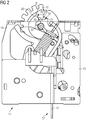
- Fig.2 an inventive switching device is shown with a switching mechanism 11.
- the switching mechanism 11 has a bevel gear segment 12, which is rotatably arranged between two preferably mutually parallel boards 13, 14.
- the bevel gear segment 12 is in operative connection with an output slide 15.
- This mechanism represents the second transmission mechanism.
- the output slide 15 has the end regions 16, 17.
- the first end region 16 of the output slide 15 is in operative connection with the bevel gear segment 12 and is designed as a catch nose 18.
- the catch nose 18 is formed as a projection 19 and as preferably formed at a 90 ° angle thereto surface area 20.
- Kegelradsegment 12 is a first locking device in the form of a geometric configuration of the catch nose 18 of the output slide 15 matching recess 21 is formed.
- the recess 21 has a preferably nose-shaped recess 22 for the projection 19 of the catch nose 18 of the output slide 15 and a preferably formed at 90 ° angle thereto surface area 23, against which the surface portion 20 of the catch nose 18 of the output slide 15 is applied.
- the projection 19 of the catch nose 18 of the drive slide 15 bears against the surface area 23 of the recess 21 of the bevel gear segment 12.
- the bevel gear 12 rotates clockwise.
- the catch nose 18 slides out of the projection 19 and surface area 20 of the drive slide 15 in the recess 21 of the bevel gear 12, the projection 19 engages the end portion 16 of the output slide 15 in the recess 22 of the recess 21 and the surface portions 20, 23 of the bevel gear 12 and the output slide 15 to each other issue.
- the output slide 15 moves downwards overall and opens the contacts.
- Fig. 3 shows the switching mechanism according to the invention in a first movement for normal shutdown.
- the bevel gear 12 rotates clockwise.
- the catch nose 18 slides out of the projection 19 and surface area 20 of the drive slide 15 in the recess 21 of the bevel gear 12, wherein the projection 19 is guided in the end portion 16 of the output slide 15 into the recess 22 of the recess 21.
- Fig. 4 the switching mechanism according to the invention is shown shortly before reaching the end point in the off state.
- the projection 19 of the catch nose 18 of the drive slide 15 engages in the recess 22 of the recess 21 of the bevel gear segment 12.
- the surface portion 23 of the recess 21 of the bevel gear 12 is almost at the surface area 20 of the catch nose 18 of the output slide 15 at.
- Fig. 5 shows the switching mechanism according to the invention in welded contacts.
- bevel gear segment 12 For welded contacts, bevel gear segment 12 must be blocked. When switching off with welded contacts, the bevel gear 12 moves initially in a clockwise direction. However, because of the welded contacts of the output slide 15 can not migrate down, he does not slip into its intended recess 21, but is blocked by a surface region of the bevel gear 12. In addition, a locking contour 24 of the bevel gear segment 12, which is arranged in the end region of the surface region 23 with the surface region 20 of the catch nose 18 of the drive slide 15. As a result, the bevel gear 12 and the knob can not be moved to the off position.
- the switching device according to the invention with a device for a reliable switch position display when welded Contacts is characterized by the fact that it is not necessary to deviate from the usual assembly operations, since the parts to be installed remain the same as in the old system. Only the functions have changed and improved. In addition, the new switch lock is more stable. As a result, even the normative test, in which the toggle is loaded with the maximum torque for welded contacts, passes without problems.
Landscapes
- Slide Switches (AREA)
- Mechanisms For Operating Contacts (AREA)
Claims (6)
- Appareil de commutation comprenant un dispositif pour un affichage fiable de la position de commutation pour des contacts soudés, présentant :- une mécanique d'actionnement qui comporte un élément d'actionnement et est, via une première mécanique de transmission, en liaison active avec un interrupteur à clé (11) qui déplace un curseur de sortie (15) via une deuxième mécanique de transmission ;- un ensemble de contact qui présente un support de pièce de commutation positionné à demeure et pourvu de contacts, qui est agencé vis-à-vis d'un support de pièce de commutation mobile pourvu de contacts, qui est guidé dans un curseur de contact,
le dispositif pour un affichage fiable de la position de commutation pour des contacts soudés étant réalisé en forme de segment de pignon conique (12) à l'intérieur de la deuxième mécanique de transmission, ce segment de pignon conique (12) étant en liaison active avec le curseur de sortie (15) et présentant deux dispositifs de blocage réalisés différemment, caractérisé en ce que le curseur de sortie (15) est en liaison active avec le segment de pignon conique (12) via un nez d'accrochage (18),
le nez d'accrochage (18) étant réalisé en tant que saillie (19) et en tant que partie de surface (20) réalisée avec un angle de 90° par rapport à cela et dans le segment de pignon conique (12) étant réalisé un premier dispositif de blocage en forme d'encoche (21) adaptée géométriquement à la configuration du nez d'accrochage (18) du curseur de sortie (15) et
l'encoche (21) présentant un évidement (22) en forme de nez pour la saillie (19) du nez d'accrochage (18) du curseur de sortie (15) et une partie de surface (23) réalisée avec un angle de 90° par rapport à cela et sur laquelle est appliquée la partie de surface (20) du nez d'accrochage (18) du curseur de sortie (15). - Appareil de commutation selon la revendication 1, caractérisé en ce qu'est réalisé, dans le segment de pignon conique (12), un premier dispositif de blocage en forme d'encoche (21) adaptée géométriquement à la configuration du nez d'accrochage (18) du curseur de sortie (15).
- Appareil de commutation selon la revendication 1 ou 2, caractérisé en ce que le segment de pignon conique (12) présente un deuxième dispositif de blocage en forme de partie de surface (23) et de contour d'arrêt.
- Appareil de commutation selon la revendication 3, caractérisé en ce que, étant donné des contacts soudés, le deuxième dispositif de blocage du segment de pignon conique (12) est en liaison active avec le nez d'accrochage (18) du curseur de sortie (15).
- Appareil de commutation selon l'une des revendications 2 à 4, caractérisé en ce que, étant donné une rotation du segment de pignon conique (12) dans le sens de la marche des aiguilles d'une montre, il est possible, étant donné des contacts non soudés, de faire passer le nez d'accrochage (18) du curseur de sortie (15) à côté du deuxième dispositif de blocage du segment de pignon conique (12) et celui-ci, pour l'état coupé de l'appareil de commutation, s'engage dans le premier dispositif de blocage.
- Selon l'une des revendications 1 à 5, caractérisé en ce que l'appareil de commutation est un commutateur de puissance.
Applications Claiming Priority (1)
| Application Number | Priority Date | Filing Date | Title |
|---|---|---|---|
| DE102016217396.0A DE102016217396A1 (de) | 2016-09-13 | 2016-09-13 | Schaltgerät mit einer Einrichtung für eine zuverlässige Schaltstellungsanzeige bei verschweißten Kontakten |
Publications (2)
| Publication Number | Publication Date |
|---|---|
| EP3293747A1 EP3293747A1 (fr) | 2018-03-14 |
| EP3293747B1 true EP3293747B1 (fr) | 2019-06-26 |
Family
ID=59295090
Family Applications (1)
| Application Number | Title | Priority Date | Filing Date |
|---|---|---|---|
| EP17180053.5A Active EP3293747B1 (fr) | 2016-09-13 | 2017-07-06 | Appareil de commutation comprenant un dispositif pour l'indication de la position de commutation fiable pour des contacts soudés |
Country Status (3)
| Country | Link |
|---|---|
| EP (1) | EP3293747B1 (fr) |
| CN (1) | CN107818891B (fr) |
| DE (1) | DE102016217396A1 (fr) |
Families Citing this family (4)
| Publication number | Priority date | Publication date | Assignee | Title |
|---|---|---|---|---|
| CN112071673B (zh) * | 2020-09-07 | 2023-02-03 | 广东电网有限责任公司 | 档位开关 |
| CN113775256A (zh) * | 2021-09-15 | 2021-12-10 | 九江精密测试技术研究所 | 一种电动锁紧机构 |
| CN114743843B (zh) * | 2022-03-24 | 2024-07-30 | 华为数字能源技术有限公司 | 动力机构、开关、功率变换装置和供电系统 |
| CN114551174B (zh) * | 2022-03-25 | 2023-08-18 | 乐星电气(无锡)有限公司 | 一种具有连锁保护机构的断路器 |
Family Cites Families (8)
| Publication number | Priority date | Publication date | Assignee | Title |
|---|---|---|---|---|
| DE19703973C1 (de) * | 1997-02-03 | 1998-05-20 | Siemens Ag | Schaltgerät mit Unterspannungs-Hilfsauslöser |
| DE19703959C1 (de) * | 1997-02-03 | 1998-04-23 | Siemens Ag | Schaltgerät mit Tripped-Stellung des Schaltschlosses |
| JP4186409B2 (ja) * | 2000-10-30 | 2008-11-26 | 富士電機機器制御株式会社 | 回路しゃ断器 |
| KR100512917B1 (ko) * | 2003-12-19 | 2005-09-06 | 엘에스산전 주식회사 | 모터보호용 차단기의 핸들구동장치 |
| CN201449912U (zh) * | 2009-05-22 | 2010-05-05 | 苏州万龙电气集团股份有限公司 | 锥齿轮式双摇杆浮杆开关装置 |
| EP2854152B1 (fr) * | 2013-09-25 | 2016-11-02 | Siemens Aktiengesellschaft | Appareil de commutation doté d'un dispositif d'activation brusque |
| CN203644687U (zh) * | 2013-10-18 | 2014-06-11 | 上海诺雅克电气有限公司 | 带脱扣类型指示的旋钮式开关电器 |
| EP3002772B1 (fr) * | 2014-10-01 | 2017-07-19 | Siemens Aktiengesellschaft | Disjoncteur doté d'un dispositif de blocage pour un affichage fiable de position |
-
2016
- 2016-09-13 DE DE102016217396.0A patent/DE102016217396A1/de not_active Withdrawn
-
2017
- 2017-07-06 EP EP17180053.5A patent/EP3293747B1/fr active Active
- 2017-09-01 CN CN201710778883.2A patent/CN107818891B/zh active Active
Non-Patent Citations (1)
| Title |
|---|
| None * |
Also Published As
| Publication number | Publication date |
|---|---|
| CN107818891A (zh) | 2018-03-20 |
| DE102016217396A1 (de) | 2018-03-15 |
| CN107818891B (zh) | 2020-03-06 |
| EP3293747A1 (fr) | 2018-03-14 |
Similar Documents
| Publication | Publication Date | Title |
|---|---|---|
| CH653188A5 (de) | Selektive sicherheitsschalteinrichtung zum schutz einer leistungsverteilungsanlage. | |
| EP3248204B1 (fr) | Disjoncteur de protection | |
| EP3293747B1 (fr) | Appareil de commutation comprenant un dispositif pour l'indication de la position de commutation fiable pour des contacts soudés | |
| DE3607052A1 (de) | Elektrisches schaltgeraet | |
| EP3002773B1 (fr) | Appareil de commutation équipé d'un dispositif d'arrêt indépendant de l'opérateur | |
| EP3175471B1 (fr) | Dispositif de commutation | |
| EP2854152B1 (fr) | Appareil de commutation doté d'un dispositif d'activation brusque | |
| EP2994930B1 (fr) | Appareil de coupure équipé d'un système d'enclenchement brusque | |
| EP4176459B1 (fr) | Mécanisme de commutation à ressort compact indépendant de l'opérateur et dispositif de commutation de protection électromécanique | |
| EP0013320B1 (fr) | Interrupteur de protection de ligne principale utilisé comme interrupteur de protection de groupe | |
| EP0350829B1 (fr) | Dispositif sélectif de protection contre les courants de court-circuit | |
| DE4023237A1 (de) | Schalteinrichtung mit einem lastschalter oder lasttrennschalter und einer sicherung | |
| EP3055875B1 (fr) | Appareil de commutation pourvu d'un élément amortisseur pour le système de contact lors d'une mise en circuit brusque | |
| EP3293751B1 (fr) | Mécanisme de commande d'un appareil de commutation basse tension | |
| DE102017131442B4 (de) | Ein- oder mehrpoliger Leistungsschalter und modulares System umfassend einen solchen Leistungsschalter | |
| EP3293750B1 (fr) | Mécanisme de commande d'un appareil de commutation basse tension | |
| DE102011079593B4 (de) | Elektromechanisches Schutzschaltgerät | |
| EP3002772B1 (fr) | Disjoncteur doté d'un dispositif de blocage pour un affichage fiable de position | |
| EP3055872A1 (fr) | Ensemble curseur de contact pour ensemble de commutation | |
| EP2824689B1 (fr) | Déclencheur dynamique et commutateur d'installation électrique doté d'un déclencheur dynamique | |
| DE3840482A1 (de) | Elektrischer selbstschalter | |
| WO2013139386A1 (fr) | Ensemble curseur de contact pour une unité de commutation, en particulier pour un disjoncteur de puissance | |
| DE689915C (de) | schalten elektrischer Stromkreise hoher Stromstaerken | |
| DE102008049554A1 (de) | Elektrischer Schalter | |
| WO2009013091A1 (fr) | Dispositif de protection électrique |
Legal Events
| Date | Code | Title | Description |
|---|---|---|---|
| PUAI | Public reference made under article 153(3) epc to a published international application that has entered the european phase |
Free format text: ORIGINAL CODE: 0009012 |
|
| STAA | Information on the status of an ep patent application or granted ep patent |
Free format text: STATUS: THE APPLICATION HAS BEEN PUBLISHED |
|
| AK | Designated contracting states |
Kind code of ref document: A1 Designated state(s): AL AT BE BG CH CY CZ DE DK EE ES FI FR GB GR HR HU IE IS IT LI LT LU LV MC MK MT NL NO PL PT RO RS SE SI SK SM TR |
|
| AX | Request for extension of the european patent |
Extension state: BA ME |
|
| STAA | Information on the status of an ep patent application or granted ep patent |
Free format text: STATUS: REQUEST FOR EXAMINATION WAS MADE |
|
| 17P | Request for examination filed |
Effective date: 20180504 |
|
| RBV | Designated contracting states (corrected) |
Designated state(s): AL AT BE BG CH CY CZ DE DK EE ES FI FR GB GR HR HU IE IS IT LI LT LU LV MC MK MT NL NO PL PT RO RS SE SI SK SM TR |
|
| GRAP | Despatch of communication of intention to grant a patent |
Free format text: ORIGINAL CODE: EPIDOSNIGR1 |
|
| STAA | Information on the status of an ep patent application or granted ep patent |
Free format text: STATUS: GRANT OF PATENT IS INTENDED |
|
| RIC1 | Information provided on ipc code assigned before grant |
Ipc: H01H 71/56 20060101ALI20190131BHEP Ipc: H01H 3/40 20060101AFI20190131BHEP Ipc: H01H 71/50 20060101ALI20190131BHEP |
|
| INTG | Intention to grant announced |
Effective date: 20190222 |
|
| GRAS | Grant fee paid |
Free format text: ORIGINAL CODE: EPIDOSNIGR3 |
|
| GRAA | (expected) grant |
Free format text: ORIGINAL CODE: 0009210 |
|
| STAA | Information on the status of an ep patent application or granted ep patent |
Free format text: STATUS: THE PATENT HAS BEEN GRANTED |
|
| AK | Designated contracting states |
Kind code of ref document: B1 Designated state(s): AL AT BE BG CH CY CZ DE DK EE ES FI FR GB GR HR HU IE IS IT LI LT LU LV MC MK MT NL NO PL PT RO RS SE SI SK SM TR |
|
| REG | Reference to a national code |
Ref country code: GB Ref legal event code: FG4D Free format text: NOT ENGLISH |
|
| REG | Reference to a national code |
Ref country code: CH Ref legal event code: EP |
|
| REG | Reference to a national code |
Ref country code: AT Ref legal event code: REF Ref document number: 1149262 Country of ref document: AT Kind code of ref document: T Effective date: 20190715 |
|
| REG | Reference to a national code |
Ref country code: DE Ref legal event code: R096 Ref document number: 502017001616 Country of ref document: DE |
|
| REG | Reference to a national code |
Ref country code: IE Ref legal event code: FG4D Free format text: LANGUAGE OF EP DOCUMENT: GERMAN |
|
| REG | Reference to a national code |
Ref country code: NL Ref legal event code: MP Effective date: 20190626 |
|
| PG25 | Lapsed in a contracting state [announced via postgrant information from national office to epo] |
Ref country code: LT Free format text: LAPSE BECAUSE OF FAILURE TO SUBMIT A TRANSLATION OF THE DESCRIPTION OR TO PAY THE FEE WITHIN THE PRESCRIBED TIME-LIMIT Effective date: 20190626 Ref country code: HR Free format text: LAPSE BECAUSE OF FAILURE TO SUBMIT A TRANSLATION OF THE DESCRIPTION OR TO PAY THE FEE WITHIN THE PRESCRIBED TIME-LIMIT Effective date: 20190626 Ref country code: NO Free format text: LAPSE BECAUSE OF FAILURE TO SUBMIT A TRANSLATION OF THE DESCRIPTION OR TO PAY THE FEE WITHIN THE PRESCRIBED TIME-LIMIT Effective date: 20190926 Ref country code: SE Free format text: LAPSE BECAUSE OF FAILURE TO SUBMIT A TRANSLATION OF THE DESCRIPTION OR TO PAY THE FEE WITHIN THE PRESCRIBED TIME-LIMIT Effective date: 20190626 Ref country code: AL Free format text: LAPSE BECAUSE OF FAILURE TO SUBMIT A TRANSLATION OF THE DESCRIPTION OR TO PAY THE FEE WITHIN THE PRESCRIBED TIME-LIMIT Effective date: 20190626 Ref country code: FI Free format text: LAPSE BECAUSE OF FAILURE TO SUBMIT A TRANSLATION OF THE DESCRIPTION OR TO PAY THE FEE WITHIN THE PRESCRIBED TIME-LIMIT Effective date: 20190626 |
|
| REG | Reference to a national code |
Ref country code: LT Ref legal event code: MG4D |
|
| PG25 | Lapsed in a contracting state [announced via postgrant information from national office to epo] |
Ref country code: BG Free format text: LAPSE BECAUSE OF FAILURE TO SUBMIT A TRANSLATION OF THE DESCRIPTION OR TO PAY THE FEE WITHIN THE PRESCRIBED TIME-LIMIT Effective date: 20190926 Ref country code: GR Free format text: LAPSE BECAUSE OF FAILURE TO SUBMIT A TRANSLATION OF THE DESCRIPTION OR TO PAY THE FEE WITHIN THE PRESCRIBED TIME-LIMIT Effective date: 20190927 Ref country code: LV Free format text: LAPSE BECAUSE OF FAILURE TO SUBMIT A TRANSLATION OF THE DESCRIPTION OR TO PAY THE FEE WITHIN THE PRESCRIBED TIME-LIMIT Effective date: 20190626 Ref country code: RS Free format text: LAPSE BECAUSE OF FAILURE TO SUBMIT A TRANSLATION OF THE DESCRIPTION OR TO PAY THE FEE WITHIN THE PRESCRIBED TIME-LIMIT Effective date: 20190626 |
|
| PG25 | Lapsed in a contracting state [announced via postgrant information from national office to epo] |
Ref country code: SK Free format text: LAPSE BECAUSE OF FAILURE TO SUBMIT A TRANSLATION OF THE DESCRIPTION OR TO PAY THE FEE WITHIN THE PRESCRIBED TIME-LIMIT Effective date: 20190626 Ref country code: PT Free format text: LAPSE BECAUSE OF FAILURE TO SUBMIT A TRANSLATION OF THE DESCRIPTION OR TO PAY THE FEE WITHIN THE PRESCRIBED TIME-LIMIT Effective date: 20191028 Ref country code: NL Free format text: LAPSE BECAUSE OF FAILURE TO SUBMIT A TRANSLATION OF THE DESCRIPTION OR TO PAY THE FEE WITHIN THE PRESCRIBED TIME-LIMIT Effective date: 20190626 Ref country code: RO Free format text: LAPSE BECAUSE OF FAILURE TO SUBMIT A TRANSLATION OF THE DESCRIPTION OR TO PAY THE FEE WITHIN THE PRESCRIBED TIME-LIMIT Effective date: 20190626 Ref country code: CZ Free format text: LAPSE BECAUSE OF FAILURE TO SUBMIT A TRANSLATION OF THE DESCRIPTION OR TO PAY THE FEE WITHIN THE PRESCRIBED TIME-LIMIT Effective date: 20190626 Ref country code: EE Free format text: LAPSE BECAUSE OF FAILURE TO SUBMIT A TRANSLATION OF THE DESCRIPTION OR TO PAY THE FEE WITHIN THE PRESCRIBED TIME-LIMIT Effective date: 20190626 |
|
| PG25 | Lapsed in a contracting state [announced via postgrant information from national office to epo] |
Ref country code: SM Free format text: LAPSE BECAUSE OF FAILURE TO SUBMIT A TRANSLATION OF THE DESCRIPTION OR TO PAY THE FEE WITHIN THE PRESCRIBED TIME-LIMIT Effective date: 20190626 Ref country code: ES Free format text: LAPSE BECAUSE OF FAILURE TO SUBMIT A TRANSLATION OF THE DESCRIPTION OR TO PAY THE FEE WITHIN THE PRESCRIBED TIME-LIMIT Effective date: 20190626 Ref country code: IS Free format text: LAPSE BECAUSE OF FAILURE TO SUBMIT A TRANSLATION OF THE DESCRIPTION OR TO PAY THE FEE WITHIN THE PRESCRIBED TIME-LIMIT Effective date: 20191026 |
|
| PG25 | Lapsed in a contracting state [announced via postgrant information from national office to epo] |
Ref country code: MC Free format text: LAPSE BECAUSE OF FAILURE TO SUBMIT A TRANSLATION OF THE DESCRIPTION OR TO PAY THE FEE WITHIN THE PRESCRIBED TIME-LIMIT Effective date: 20190626 Ref country code: TR Free format text: LAPSE BECAUSE OF FAILURE TO SUBMIT A TRANSLATION OF THE DESCRIPTION OR TO PAY THE FEE WITHIN THE PRESCRIBED TIME-LIMIT Effective date: 20190626 |
|
| REG | Reference to a national code |
Ref country code: BE Ref legal event code: MM Effective date: 20190731 |
|
| PG25 | Lapsed in a contracting state [announced via postgrant information from national office to epo] |
Ref country code: PL Free format text: LAPSE BECAUSE OF FAILURE TO SUBMIT A TRANSLATION OF THE DESCRIPTION OR TO PAY THE FEE WITHIN THE PRESCRIBED TIME-LIMIT Effective date: 20190626 Ref country code: DK Free format text: LAPSE BECAUSE OF FAILURE TO SUBMIT A TRANSLATION OF THE DESCRIPTION OR TO PAY THE FEE WITHIN THE PRESCRIBED TIME-LIMIT Effective date: 20190626 |
|
| PG25 | Lapsed in a contracting state [announced via postgrant information from national office to epo] |
Ref country code: BE Free format text: LAPSE BECAUSE OF NON-PAYMENT OF DUE FEES Effective date: 20190731 Ref country code: LU Free format text: LAPSE BECAUSE OF NON-PAYMENT OF DUE FEES Effective date: 20190706 Ref country code: IS Free format text: LAPSE BECAUSE OF FAILURE TO SUBMIT A TRANSLATION OF THE DESCRIPTION OR TO PAY THE FEE WITHIN THE PRESCRIBED TIME-LIMIT Effective date: 20200320 |
|
| REG | Reference to a national code |
Ref country code: DE Ref legal event code: R097 Ref document number: 502017001616 Country of ref document: DE |
|
| PLBE | No opposition filed within time limit |
Free format text: ORIGINAL CODE: 0009261 |
|
| STAA | Information on the status of an ep patent application or granted ep patent |
Free format text: STATUS: NO OPPOSITION FILED WITHIN TIME LIMIT |
|
| PG2D | Information on lapse in contracting state deleted |
Ref country code: IS |
|
| PG25 | Lapsed in a contracting state [announced via postgrant information from national office to epo] |
Ref country code: IE Free format text: LAPSE BECAUSE OF NON-PAYMENT OF DUE FEES Effective date: 20190706 |
|
| 26N | No opposition filed |
Effective date: 20200603 |
|
| PG25 | Lapsed in a contracting state [announced via postgrant information from national office to epo] |
Ref country code: SI Free format text: LAPSE BECAUSE OF FAILURE TO SUBMIT A TRANSLATION OF THE DESCRIPTION OR TO PAY THE FEE WITHIN THE PRESCRIBED TIME-LIMIT Effective date: 20190626 |
|
| REG | Reference to a national code |
Ref country code: CH Ref legal event code: PL |
|
| PG25 | Lapsed in a contracting state [announced via postgrant information from national office to epo] |
Ref country code: CH Free format text: LAPSE BECAUSE OF NON-PAYMENT OF DUE FEES Effective date: 20200731 Ref country code: LI Free format text: LAPSE BECAUSE OF NON-PAYMENT OF DUE FEES Effective date: 20200731 |
|
| PG25 | Lapsed in a contracting state [announced via postgrant information from national office to epo] |
Ref country code: CY Free format text: LAPSE BECAUSE OF FAILURE TO SUBMIT A TRANSLATION OF THE DESCRIPTION OR TO PAY THE FEE WITHIN THE PRESCRIBED TIME-LIMIT Effective date: 20190626 |
|
| PG25 | Lapsed in a contracting state [announced via postgrant information from national office to epo] |
Ref country code: HU Free format text: LAPSE BECAUSE OF FAILURE TO SUBMIT A TRANSLATION OF THE DESCRIPTION OR TO PAY THE FEE WITHIN THE PRESCRIBED TIME-LIMIT; INVALID AB INITIO Effective date: 20170706 Ref country code: MT Free format text: LAPSE BECAUSE OF FAILURE TO SUBMIT A TRANSLATION OF THE DESCRIPTION OR TO PAY THE FEE WITHIN THE PRESCRIBED TIME-LIMIT Effective date: 20190626 |
|
| GBPC | Gb: european patent ceased through non-payment of renewal fee |
Effective date: 20210706 |
|
| PG25 | Lapsed in a contracting state [announced via postgrant information from national office to epo] |
Ref country code: GB Free format text: LAPSE BECAUSE OF NON-PAYMENT OF DUE FEES Effective date: 20210706 |
|
| PG25 | Lapsed in a contracting state [announced via postgrant information from national office to epo] |
Ref country code: MK Free format text: LAPSE BECAUSE OF FAILURE TO SUBMIT A TRANSLATION OF THE DESCRIPTION OR TO PAY THE FEE WITHIN THE PRESCRIBED TIME-LIMIT Effective date: 20190626 |
|
| P01 | Opt-out of the competence of the unified patent court (upc) registered |
Effective date: 20230512 |
|
| REG | Reference to a national code |
Ref country code: AT Ref legal event code: MM01 Ref document number: 1149262 Country of ref document: AT Kind code of ref document: T Effective date: 20220706 |
|
| PG25 | Lapsed in a contracting state [announced via postgrant information from national office to epo] |
Ref country code: AT Free format text: LAPSE BECAUSE OF NON-PAYMENT OF DUE FEES Effective date: 20220706 |
|
| PGFP | Annual fee paid to national office [announced via postgrant information from national office to epo] |
Ref country code: FR Payment date: 20230720 Year of fee payment: 7 |
|
| PG25 | Lapsed in a contracting state [announced via postgrant information from national office to epo] |
Ref country code: FR Free format text: LAPSE BECAUSE OF NON-PAYMENT OF DUE FEES Effective date: 20240731 |
|
| PGFP | Annual fee paid to national office [announced via postgrant information from national office to epo] |
Ref country code: DE Payment date: 20250919 Year of fee payment: 9 |
|
| PGFP | Annual fee paid to national office [announced via postgrant information from national office to epo] |
Ref country code: IT Payment date: 20250718 Year of fee payment: 9 |