EP3293751B1 - Mécanisme de commande d'un appareil de commutation basse tension - Google Patents
Mécanisme de commande d'un appareil de commutation basse tension Download PDFInfo
- Publication number
- EP3293751B1 EP3293751B1 EP17181325.6A EP17181325A EP3293751B1 EP 3293751 B1 EP3293751 B1 EP 3293751B1 EP 17181325 A EP17181325 A EP 17181325A EP 3293751 B1 EP3293751 B1 EP 3293751B1
- Authority
- EP
- European Patent Office
- Prior art keywords
- operating mechanism
- blocking part
- switch
- locking part
- switching
- Prior art date
- Legal status (The legal status is an assumption and is not a legal conclusion. Google has not performed a legal analysis and makes no representation as to the accuracy of the status listed.)
- Active
Links
Images


Classifications
-
- H—ELECTRICITY
- H01—ELECTRIC ELEMENTS
- H01H—ELECTRIC SWITCHES; RELAYS; SELECTORS; EMERGENCY PROTECTIVE DEVICES
- H01H71/00—Details of the protective switches or relays covered by groups H01H73/00 - H01H83/00
- H01H71/10—Operating or release mechanisms
- H01H71/1009—Interconnected mechanisms
-
- H—ELECTRICITY
- H01—ELECTRIC ELEMENTS
- H01H—ELECTRIC SWITCHES; RELAYS; SELECTORS; EMERGENCY PROTECTIVE DEVICES
- H01H71/00—Details of the protective switches or relays covered by groups H01H73/00 - H01H83/00
- H01H71/10—Operating or release mechanisms
- H01H71/50—Manual reset mechanisms which may be also used for manual release
- H01H71/52—Manual reset mechanisms which may be also used for manual release actuated by lever
- H01H71/528—Manual reset mechanisms which may be also used for manual release actuated by lever comprising a toggle or collapsible link between handle and contact arm, e.g. sear pin mechanism
-
- H—ELECTRICITY
- H01—ELECTRIC ELEMENTS
- H01H—ELECTRIC SWITCHES; RELAYS; SELECTORS; EMERGENCY PROTECTIVE DEVICES
- H01H71/00—Details of the protective switches or relays covered by groups H01H73/00 - H01H83/00
- H01H71/10—Operating or release mechanisms
- H01H71/50—Manual reset mechanisms which may be also used for manual release
- H01H71/504—Manual reset mechanisms which may be also used for manual release provided with anti-rebound means
-
- H—ELECTRICITY
- H01—ELECTRIC ELEMENTS
- H01H—ELECTRIC SWITCHES; RELAYS; SELECTORS; EMERGENCY PROTECTIVE DEVICES
- H01H11/00—Apparatus or processes specially adapted for the manufacture of electric switches
- H01H11/0006—Apparatus or processes specially adapted for the manufacture of electric switches for converting electric switches
-
- H—ELECTRICITY
- H01—ELECTRIC ELEMENTS
- H01H—ELECTRIC SWITCHES; RELAYS; SELECTORS; EMERGENCY PROTECTIVE DEVICES
- H01H2300/00—Orthogonal indexing scheme relating to electric switches, relays, selectors or emergency protective devices covered by H01H
- H01H2300/046—Orthogonal indexing scheme relating to electric switches, relays, selectors or emergency protective devices covered by H01H using snap closing mechanisms
-
- H—ELECTRICITY
- H01—ELECTRIC ELEMENTS
- H01H—ELECTRIC SWITCHES; RELAYS; SELECTORS; EMERGENCY PROTECTIVE DEVICES
- H01H71/00—Details of the protective switches or relays covered by groups H01H73/00 - H01H83/00
- H01H71/10—Operating or release mechanisms
- H01H71/50—Manual reset mechanisms which may be also used for manual release
- H01H71/56—Manual reset mechanisms which may be also used for manual release actuated by rotatable knob or wheel
Definitions
- the invention relates to a switch lock for a low-voltage protection device with two opposing circuit boards, a rotatable handle being arranged between the circuit boards, which is operatively connected to a roller via a bracket.
- Low-voltage protective devices in particular circuit breakers, are used, among other things, to safely switch off in the event of a short circuit and thereby protect consumer systems.
- electrical or mechanical switching units are suitable for the operational manual switching of consumers and for the safe disconnection of a system from the power supply during maintenance work or changes to the system. Electrical switching units are often operated electromagnetically.
- switching units are high-quality electrical switching devices with integrated protection for motors, lines, transformers and generators. They are used more closely at function points with a lower switching frequency. Such switching units are also suitable for overload protection in addition to short-circuit protection.
- an electrical switching unit In the event of a short circuit, an electrical switching unit safely switches off an electrical system. Thus, this offers protection against overload. Every conductor through which current flows heats up to a greater or lesser extent. The heating depends on the ratio of the current strength to the conductor cross-section, the so-called current density. The current density must not be too high, since otherwise the conductor insulation may burn up due to excessive heating or a fire may start. In order to protect electrical systems against this damaging effect, switching units are used as overcurrent protection devices.
- Circuit breakers have two separate trigger mechanisms for overload and short-circuit protection. Both triggers are connected in series. Protection in the event of a short circuit is provided by an electrical release that acts almost instantaneously. In the event of a short circuit, the electromagnetic release immediately releases a circuit breaker on the circuit breaker. A switch armature separates the contact piece before the short-circuit current can reach its maximum value.
- switching units have a contact slide unit with a contact slide and a movable contact piece.
- the movable contact piece also has electrical contacts.
- switching units have first contacts to a power line.
- the electrical contacts of the movable contact piece contact the fixed contacts of the switching unit.
- the electrical contacts of the movable contact are released from the fixed contacts, so that the current flow is interrupted.
- the movable contact piece is released from the contacts.
- circuit breakers In addition to their protective functions as overload and short-circuit releases, as already mentioned above, circuit breakers also fulfill the normative switching on and off of motors. To demonstrate these functions, the circuit breakers must be able to switch on ten times the rated motor current according to the product standard. In order to be able to guarantee this limit load, it is necessary that the circuit breaker closes the double interruption of the three current paths in the form of a movable bridge with two movable contact points and two fixed contact points, almost simultaneously and in a step function.
- the contact apparatus consisting of a contact slide and a movable bridge is released via a manually operated mechanism, in the form of an actuating element, a key switch and an actuating chain.
- the Release takes place through a so-called quick activation.
- the three contact systems are only released by a mechanism after the key switch has already been switched on.
- the spring accumulator in the form of a contact load spring now determines the kinematics of the contact system when it is switched on.
- the contact slide accelerates until it is reflected at a stop.
- the reflection and the resulting kinetic energy of the contact slide result in the contact system being reopened. With a simultaneously increased current in this current path, this can lead to welds.
- circuit breakers of these circuit breakers could be provided with a quick switch-on in the form of a retrofit process by simple structural measures.
- the DE 197 03 977 C1 describes a switch lock for a low-voltage protection device with two opposing circuit boards, a rotatable handle being arranged between the circuit boards, which is operatively connected to a roller via a lever, the roller being operatively connected to a device for swinging switching, via which a switching lever is to be moved into a corresponding switch position.
- From the DE 35 08 110 A1 shows a switch lock for a low-voltage protection device, the switch lock having a device for sudden switching on.
- This device for sudden switching on comprises an integrally connected locking member with an extension which has a circular contour facing a disk in the outlet, on which the disc can roll.
- the locking member can be retrofitted.
- the object of the present invention is to provide a switch lock for a low-voltage protection device with a retrofittable device for sudden switching on.
- this object is achieved by a switch lock for a low-voltage protection device with two circuit boards lying opposite one another, a rotatable handle being arranged between the circuit boards and being operatively connected to a roller via a bracket.
- the invention is characterized in that the roller is in operative connection with a retrofittable device for swinging switching, via which a shift lever can be moved into a corresponding shift position.
- the essence of the invention is that the retrofittable device for switching on suddenly requires only a single switch lock subassembly, which can be manufactured and tested completely automatically.
- the retrofittable device according to the invention for switching on suddenly has a locking part and a return spring which can be retrofitted to adapt the switch lock for larger nominal currents. First, the locking part is snapped into the bearing pin on which the shift lever is also arranged. Then the return spring is snapped with the locking part.
- the return spring is designed so that it can be easily and safely installed.
- the locking part is still within the key switch geometry and does not require any additional installation space within the complete device.
- a continuation of the concept according to the invention can provide that the device for switching on suddenly has a blocking part.
- a special embodiment of the concept according to the invention can consist in that the locking part can be snapped onto a bearing on which the shift lever is also positioned.
- An advantageous embodiment of the concept according to the invention can consist in that the locking part is Z-shaped with two tongues formed parallel to one another and a central region connecting the tongues.
- a continuation of this concept according to the invention can consist in that a semi-concentric extension is formed on the connecting central region, via which the locking part snaps onto the bearing, so that the shift lever and the locking part are mounted in the same bearing point.
- a continuation of the concept according to the invention can provide that the tongue of the locking part is operatively connected to the roller.
- a special embodiment of this concept according to the invention can provide that the device for switching on suddenly has a return spring.
- An advantageous embodiment of the concept according to the invention can consist in the fact that the return spring has J-shaped sections which are connected to one another via a connecting area.
- a continuation of the concept according to the invention can provide that the J-shaped sections of the return spring are fastened to the tongue of the locking part and to the circuit board.
- the switch lock according to the invention for a low-voltage protection device has two opposing circuit boards, a rotatable handle being arranged between the circuit boards, which is operatively connected to a roller via a bracket.
- the role is in operative connection with a retrofittable device for swinging switching, via which a shift lever can be moved into a corresponding switching position.
- the device for sudden switching on has a locking part and a return spring.
- the locking part is Z-shaped with two tongues formed parallel to each other and a central area connecting the tongues.
- a semi-concentric extension is formed on the connecting central region of the locking part, via which the locking part snaps onto a bearing, the shift lever and the locking part being mounted in the same bearing point.
- the tongue of the locking part is operatively connected to the roller. The assembly provides that the locking part is first snapped onto the bearing and then the return spring is snapped onto the locking part.
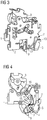
- a switch lock from the prior art is shown.
- the switch lock has two opposite circuit boards 1, 2, a rotatably mounted handle 3 being arranged between the circuit boards 1, 2.
- the handle 3 is operatively connected via a transmission mechanism to a shift lever 5 arranged on a bearing 4.
- the Fig. 1 shows a key switch without quick start function.
- FIG. 2 A switch lock according to the invention is shown with a separately shown retrofittable device for switching on suddenly in the form of a locking part 6 and a return spring 7.
- the switch lock according to the invention also has two opposing circuit boards 1, 2, a rotatable handle 3 being arranged between the circuit boards 1, 2 is in operative connection via a transmission mechanism with a shift lever 5 arranged on the bearing 4.
- the locking part 6 is Z-shaped with two mutually parallel tongues 8, 9 and a central region 10 connecting the tongues 8, 9.
- a semi-concentric extension 11 is formed on the connecting central region 10, via which the locking part 6 snaps onto the bearing 4 , so that the shift lever 5 and the locking part 6 are mounted in the same bearing point.
- the return spring 7 has two J-shaped sections 12, 13 which are connected to one another via a connecting region 14.
- Fig. 3 the switch lock according to the invention is shown with a mounted, retrofittable device for sudden switching on.
- a J-shaped section 12 of the return spring 7 is fastened to the tongue 9 of the locking part 6.
- the other J-shaped section 13 of the return spring 7 is attached to the circuit board 2 of the key switch.
- Fig. 4 the switch lock according to the invention is shown with the transmission mechanism of bracket 15 and roller 16 in the switched-off position.
- the roller 16 is spaced from the tongue 8 of the locking part 6.
- the semi-concentric extension 11 are mounted on the locking part 6 together with the shift lever 5 in a bearing 4.
- Fig. 5 shows the switch lock according to the invention with the transmission mechanism of bracket 15 and roller 16 at the beginning of the deflection of the locking part 6.
- the roller 16 moves by the deflection towards the tongue 8 of the locking part 6 until the roller 16 and the tongue 8 of the locking part 6 one have a common point of contact.
- the shift lever 5, which is positioned with the locking part 6 on the bearing 4 then also moves.
- Fig. 6 the switch lock according to the invention is shown with the transmission mechanism of bracket 15 and roller 16 in the switched-on position.
- the switch lock according to the invention for low-voltage protection devices with a retrofittable device for sudden switching on is characterized in that by the subsequent Installation of the locking part or the return spring, the variance of the preassembled key switch assembly is reduced.
- a pre-assembled standard switch lock can be used again, which is then configured depending on the use via the differently designed tension springs and a retrofittable locking part. This reduces the storage and handling effort.
- the need for switch locks with quick activation can be controlled as required and without great effort.
- the previously complicated manual assembly of the preassembled switch lock assembly is no longer necessary and is replaced by the simple subsequent assembly on the finished assembly.
- the locking part is still located within the key switch geometry and does not require any additional installation space within the complete device.
Landscapes
- Switch Cases, Indication, And Locking (AREA)
- Driving Mechanisms And Operating Circuits Of Arc-Extinguishing High-Tension Switches (AREA)
Claims (7)
- Verrou de commande pour un appareil de protection basse tension avec deux cartes de commande en vis-à-vis (1,2), entre les cartes de commande (1,2) étant agencée une poignée rotative (3) qui est en liaison active avec un rouleau (16) via une tige (15), le rouleau (16) étant en liaison active avec un dispositif d'enclenchement brusque pouvant être ajouté et via lequel un levier de commande (5) doit être mis dans une position de commande appropriée, le dispositif d'enclenchement brusque présentant une pièce de blocage (6), caractérisé en ce que la pièce de blocage (6) peut s'encliqueter sur un palier (4) sur lequel est également positionné le levier de commande (5).
- Verrou de commande selon la revendication 1, caractérisé en ce que la pièce de blocage (6) est réalisée en forme de Z avec deux langues (8, 9) parallèles entre elles et une partie centrale (10) reliant les langues (8,9).
- Verrou de commande selon la revendication 2, caractérisé en ce qu'est formé, sur la partie centrale de liaison (10), un prolongement semi-concentrique (11) via lequel la pièce de blocage (6) s'encliquette sur le palier (4), de sorte que le levier de commande (5) et la pièce de blocage (6) reposent sur le même point de palier.
- Verrou de commande selon la revendication 2, caractérisé en ce que la langue (8) de la pièce de blocage (6) est en liaison active avec le rouleau (16).
- Verrou de commande selon l'une des revendications 1 à 4, caractérisé en ce que le dispositif d'enclenchement brusque comporte un ressort de rappel (7).
- Verrou de commande selon la revendication 5, caractérisé en ce que le ressort de rappel (7) présente deux parties (12, 13) réalisées en forme de J qui sont reliées entre elles via une zone de liaison (14).
- Verrou de commande selon la revendication 6, caractérisé en ce que les parties (12, 13) en forme de J du ressort de rappel (7) sont fixées sur la langue (9) de la pièce de blocage (6) ainsi que sur la carte de commande (2).
Applications Claiming Priority (1)
| Application Number | Priority Date | Filing Date | Title |
|---|---|---|---|
| DE102016217225.5A DE102016217225A1 (de) | 2016-09-09 | 2016-09-09 | Schaltschloss für ein Niederspannungsschutzgerät |
Publications (2)
| Publication Number | Publication Date |
|---|---|
| EP3293751A1 EP3293751A1 (fr) | 2018-03-14 |
| EP3293751B1 true EP3293751B1 (fr) | 2019-12-18 |
Family
ID=59350741
Family Applications (1)
| Application Number | Title | Priority Date | Filing Date |
|---|---|---|---|
| EP17181325.6A Active EP3293751B1 (fr) | 2016-09-09 | 2017-07-14 | Mécanisme de commande d'un appareil de commutation basse tension |
Country Status (3)
| Country | Link |
|---|---|
| EP (1) | EP3293751B1 (fr) |
| CN (1) | CN107808802B (fr) |
| DE (1) | DE102016217225A1 (fr) |
Cited By (1)
| Publication number | Priority date | Publication date | Assignee | Title |
|---|---|---|---|---|
| US11437202B2 (en) | 2020-06-29 | 2022-09-06 | Rockwell Automation Switzerland Gmbh | Switching device with lock open component |
Family Cites Families (5)
| Publication number | Priority date | Publication date | Assignee | Title |
|---|---|---|---|---|
| DE3508110A1 (de) * | 1985-03-07 | 1986-09-11 | Felten & Guilleaume Energietechnik GmbH, 5000 Köln | Schaltschloss mit schnelleinschaltung |
| DE19703977C1 (de) * | 1997-02-03 | 1998-05-14 | Siemens Ag | Schaltgerät mit Schnelleinschaltung |
| DE19703959C1 (de) * | 1997-02-03 | 1998-04-23 | Siemens Ag | Schaltgerät mit Tripped-Stellung des Schaltschlosses |
| WO2015043632A1 (fr) * | 2013-09-25 | 2015-04-02 | Siemens Aktiengesellschaft | Appareil de coupure équipé d'un système d'enclenchement brusque |
| EP3002773B1 (fr) * | 2014-10-01 | 2017-03-22 | Siemens Aktiengesellschaft | Appareil de commutation équipé d'un dispositif d'arrêt indépendant de l'opérateur |
-
2016
- 2016-09-09 DE DE102016217225.5A patent/DE102016217225A1/de not_active Withdrawn
-
2017
- 2017-07-14 EP EP17181325.6A patent/EP3293751B1/fr active Active
- 2017-08-07 CN CN201710668587.7A patent/CN107808802B/zh not_active Expired - Fee Related
Non-Patent Citations (1)
| Title |
|---|
| None * |
Cited By (1)
| Publication number | Priority date | Publication date | Assignee | Title |
|---|---|---|---|---|
| US11437202B2 (en) | 2020-06-29 | 2022-09-06 | Rockwell Automation Switzerland Gmbh | Switching device with lock open component |
Also Published As
| Publication number | Publication date |
|---|---|
| CN107808802A (zh) | 2018-03-16 |
| DE102016217225A1 (de) | 2018-03-15 |
| CN107808802B (zh) | 2019-11-12 |
| EP3293751A1 (fr) | 2018-03-14 |
Similar Documents
| Publication | Publication Date | Title |
|---|---|---|
| CH653188A5 (de) | Selektive sicherheitsschalteinrichtung zum schutz einer leistungsverteilungsanlage. | |
| EP3293747B1 (fr) | Appareil de commutation comprenant un dispositif pour l'indication de la position de commutation fiable pour des contacts soudés | |
| EP3002773B1 (fr) | Appareil de commutation équipé d'un dispositif d'arrêt indépendant de l'opérateur | |
| EP3175471B1 (fr) | Dispositif de commutation | |
| EP2854152B1 (fr) | Appareil de commutation doté d'un dispositif d'activation brusque | |
| EP3439004A1 (fr) | Élément de déclenchement d'un déclencheur par pression, déclencheur par pression doté d'un tel élément de déclenchement et commutateur électrique | |
| EP3293751B1 (fr) | Mécanisme de commande d'un appareil de commutation basse tension | |
| DE102008016575B4 (de) | Voll-Schutzschalter und motorsteuerbarer Vollschutzschalter | |
| EP2994930B1 (fr) | Appareil de coupure équipé d'un système d'enclenchement brusque | |
| DE102008026813A1 (de) | Elektrischer selektiver Selbstschalter | |
| EP3293750B1 (fr) | Mécanisme de commande d'un appareil de commutation basse tension | |
| EP2704171A1 (fr) | Unité à curseur de contact pour une unité de commutation, notamment pour un disjoncteur | |
| EP3055875B1 (fr) | Appareil de commutation pourvu d'un élément amortisseur pour le système de contact lors d'une mise en circuit brusque | |
| DE102013114402A1 (de) | Schaltgerät | |
| EP3002772B1 (fr) | Disjoncteur doté d'un dispositif de blocage pour un affichage fiable de position | |
| DE102011079593B4 (de) | Elektromechanisches Schutzschaltgerät | |
| EP3258231A1 (fr) | Appareil de protection électromécanique comprenant un dispositif de déclenchement contre la surcharge | |
| EP0371419A2 (fr) | Disjoncteur électrique | |
| EP2824689B1 (fr) | Déclencheur dynamique et commutateur d'installation électrique doté d'un déclencheur dynamique | |
| DE102016203508B4 (de) | Auslösevorrichtung und elektromechanisches Schutzschaltgerät | |
| EP3055872A1 (fr) | Ensemble curseur de contact pour ensemble de commutation | |
| EP2680293A1 (fr) | Mécanisme de déclenchement | |
| DE102008049554A1 (de) | Elektrischer Schalter | |
| DE102008007363A1 (de) | Drehkontaktsystem für ein Schaltgerät sowie Schaltgeräte mit einem derartigen Drehkontaktsystem | |
| DE102017202790B4 (de) | Elektromechanisches Schutzschaltgerät |
Legal Events
| Date | Code | Title | Description |
|---|---|---|---|
| PUAI | Public reference made under article 153(3) epc to a published international application that has entered the european phase |
Free format text: ORIGINAL CODE: 0009012 |
|
| STAA | Information on the status of an ep patent application or granted ep patent |
Free format text: STATUS: THE APPLICATION HAS BEEN PUBLISHED |
|
| AK | Designated contracting states |
Kind code of ref document: A1 Designated state(s): AL AT BE BG CH CY CZ DE DK EE ES FI FR GB GR HR HU IE IS IT LI LT LU LV MC MK MT NL NO PL PT RO RS SE SI SK SM TR |
|
| AX | Request for extension of the european patent |
Extension state: BA ME |
|
| STAA | Information on the status of an ep patent application or granted ep patent |
Free format text: STATUS: REQUEST FOR EXAMINATION WAS MADE |
|
| 17P | Request for examination filed |
Effective date: 20180504 |
|
| RBV | Designated contracting states (corrected) |
Designated state(s): AL AT BE BG CH CY CZ DE DK EE ES FI FR GB GR HR HU IE IS IT LI LT LU LV MC MK MT NL NO PL PT RO RS SE SI SK SM TR |
|
| GRAP | Despatch of communication of intention to grant a patent |
Free format text: ORIGINAL CODE: EPIDOSNIGR1 |
|
| STAA | Information on the status of an ep patent application or granted ep patent |
Free format text: STATUS: GRANT OF PATENT IS INTENDED |
|
| RIC1 | Information provided on ipc code assigned before grant |
Ipc: H01H 71/52 20060101AFI20190711BHEP Ipc: H01H 71/56 20060101ALN20190711BHEP Ipc: H01H 71/50 20060101ALI20190711BHEP Ipc: H01H 11/00 20060101ALN20190711BHEP |
|
| INTG | Intention to grant announced |
Effective date: 20190801 |
|
| GRAS | Grant fee paid |
Free format text: ORIGINAL CODE: EPIDOSNIGR3 |
|
| GRAA | (expected) grant |
Free format text: ORIGINAL CODE: 0009210 |
|
| STAA | Information on the status of an ep patent application or granted ep patent |
Free format text: STATUS: THE PATENT HAS BEEN GRANTED |
|
| AK | Designated contracting states |
Kind code of ref document: B1 Designated state(s): AL AT BE BG CH CY CZ DE DK EE ES FI FR GB GR HR HU IE IS IT LI LT LU LV MC MK MT NL NO PL PT RO RS SE SI SK SM TR |
|
| REG | Reference to a national code |
Ref country code: CH Ref legal event code: EP |
|
| REG | Reference to a national code |
Ref country code: DE Ref legal event code: R096 Ref document number: 502017003162 Country of ref document: DE |
|
| REG | Reference to a national code |
Ref country code: IE Ref legal event code: FG4D Free format text: LANGUAGE OF EP DOCUMENT: GERMAN |
|
| REG | Reference to a national code |
Ref country code: AT Ref legal event code: REF Ref document number: 1215513 Country of ref document: AT Kind code of ref document: T Effective date: 20200115 |
|
| REG | Reference to a national code |
Ref country code: NL Ref legal event code: MP Effective date: 20191218 |
|
| PG25 | Lapsed in a contracting state [announced via postgrant information from national office to epo] |
Ref country code: NO Free format text: LAPSE BECAUSE OF FAILURE TO SUBMIT A TRANSLATION OF THE DESCRIPTION OR TO PAY THE FEE WITHIN THE PRESCRIBED TIME-LIMIT Effective date: 20200318 Ref country code: GR Free format text: LAPSE BECAUSE OF FAILURE TO SUBMIT A TRANSLATION OF THE DESCRIPTION OR TO PAY THE FEE WITHIN THE PRESCRIBED TIME-LIMIT Effective date: 20200319 Ref country code: LT Free format text: LAPSE BECAUSE OF FAILURE TO SUBMIT A TRANSLATION OF THE DESCRIPTION OR TO PAY THE FEE WITHIN THE PRESCRIBED TIME-LIMIT Effective date: 20191218 Ref country code: SE Free format text: LAPSE BECAUSE OF FAILURE TO SUBMIT A TRANSLATION OF THE DESCRIPTION OR TO PAY THE FEE WITHIN THE PRESCRIBED TIME-LIMIT Effective date: 20191218 Ref country code: LV Free format text: LAPSE BECAUSE OF FAILURE TO SUBMIT A TRANSLATION OF THE DESCRIPTION OR TO PAY THE FEE WITHIN THE PRESCRIBED TIME-LIMIT Effective date: 20191218 Ref country code: FI Free format text: LAPSE BECAUSE OF FAILURE TO SUBMIT A TRANSLATION OF THE DESCRIPTION OR TO PAY THE FEE WITHIN THE PRESCRIBED TIME-LIMIT Effective date: 20191218 Ref country code: BG Free format text: LAPSE BECAUSE OF FAILURE TO SUBMIT A TRANSLATION OF THE DESCRIPTION OR TO PAY THE FEE WITHIN THE PRESCRIBED TIME-LIMIT Effective date: 20200318 |
|
| REG | Reference to a national code |
Ref country code: LT Ref legal event code: MG4D |
|
| PG25 | Lapsed in a contracting state [announced via postgrant information from national office to epo] |
Ref country code: RS Free format text: LAPSE BECAUSE OF FAILURE TO SUBMIT A TRANSLATION OF THE DESCRIPTION OR TO PAY THE FEE WITHIN THE PRESCRIBED TIME-LIMIT Effective date: 20191218 Ref country code: HR Free format text: LAPSE BECAUSE OF FAILURE TO SUBMIT A TRANSLATION OF THE DESCRIPTION OR TO PAY THE FEE WITHIN THE PRESCRIBED TIME-LIMIT Effective date: 20191218 |
|
| PG25 | Lapsed in a contracting state [announced via postgrant information from national office to epo] |
Ref country code: AL Free format text: LAPSE BECAUSE OF FAILURE TO SUBMIT A TRANSLATION OF THE DESCRIPTION OR TO PAY THE FEE WITHIN THE PRESCRIBED TIME-LIMIT Effective date: 20191218 |
|
| PG25 | Lapsed in a contracting state [announced via postgrant information from national office to epo] |
Ref country code: EE Free format text: LAPSE BECAUSE OF FAILURE TO SUBMIT A TRANSLATION OF THE DESCRIPTION OR TO PAY THE FEE WITHIN THE PRESCRIBED TIME-LIMIT Effective date: 20191218 Ref country code: PT Free format text: LAPSE BECAUSE OF FAILURE TO SUBMIT A TRANSLATION OF THE DESCRIPTION OR TO PAY THE FEE WITHIN THE PRESCRIBED TIME-LIMIT Effective date: 20200513 Ref country code: NL Free format text: LAPSE BECAUSE OF FAILURE TO SUBMIT A TRANSLATION OF THE DESCRIPTION OR TO PAY THE FEE WITHIN THE PRESCRIBED TIME-LIMIT Effective date: 20191218 Ref country code: RO Free format text: LAPSE BECAUSE OF FAILURE TO SUBMIT A TRANSLATION OF THE DESCRIPTION OR TO PAY THE FEE WITHIN THE PRESCRIBED TIME-LIMIT Effective date: 20191218 Ref country code: CZ Free format text: LAPSE BECAUSE OF FAILURE TO SUBMIT A TRANSLATION OF THE DESCRIPTION OR TO PAY THE FEE WITHIN THE PRESCRIBED TIME-LIMIT Effective date: 20191218 |
|
| PG25 | Lapsed in a contracting state [announced via postgrant information from national office to epo] |
Ref country code: SM Free format text: LAPSE BECAUSE OF FAILURE TO SUBMIT A TRANSLATION OF THE DESCRIPTION OR TO PAY THE FEE WITHIN THE PRESCRIBED TIME-LIMIT Effective date: 20191218 Ref country code: SK Free format text: LAPSE BECAUSE OF FAILURE TO SUBMIT A TRANSLATION OF THE DESCRIPTION OR TO PAY THE FEE WITHIN THE PRESCRIBED TIME-LIMIT Effective date: 20191218 Ref country code: IS Free format text: LAPSE BECAUSE OF FAILURE TO SUBMIT A TRANSLATION OF THE DESCRIPTION OR TO PAY THE FEE WITHIN THE PRESCRIBED TIME-LIMIT Effective date: 20200418 |
|
| REG | Reference to a national code |
Ref country code: DE Ref legal event code: R097 Ref document number: 502017003162 Country of ref document: DE |
|
| PLBE | No opposition filed within time limit |
Free format text: ORIGINAL CODE: 0009261 |
|
| STAA | Information on the status of an ep patent application or granted ep patent |
Free format text: STATUS: NO OPPOSITION FILED WITHIN TIME LIMIT |
|
| PG25 | Lapsed in a contracting state [announced via postgrant information from national office to epo] |
Ref country code: DK Free format text: LAPSE BECAUSE OF FAILURE TO SUBMIT A TRANSLATION OF THE DESCRIPTION OR TO PAY THE FEE WITHIN THE PRESCRIBED TIME-LIMIT Effective date: 20191218 Ref country code: ES Free format text: LAPSE BECAUSE OF FAILURE TO SUBMIT A TRANSLATION OF THE DESCRIPTION OR TO PAY THE FEE WITHIN THE PRESCRIBED TIME-LIMIT Effective date: 20191218 |
|
| 26N | No opposition filed |
Effective date: 20200921 |
|
| PG25 | Lapsed in a contracting state [announced via postgrant information from national office to epo] |
Ref country code: SI Free format text: LAPSE BECAUSE OF FAILURE TO SUBMIT A TRANSLATION OF THE DESCRIPTION OR TO PAY THE FEE WITHIN THE PRESCRIBED TIME-LIMIT Effective date: 20191218 |
|
| PG25 | Lapsed in a contracting state [announced via postgrant information from national office to epo] |
Ref country code: MC Free format text: LAPSE BECAUSE OF FAILURE TO SUBMIT A TRANSLATION OF THE DESCRIPTION OR TO PAY THE FEE WITHIN THE PRESCRIBED TIME-LIMIT Effective date: 20191218 Ref country code: PL Free format text: LAPSE BECAUSE OF FAILURE TO SUBMIT A TRANSLATION OF THE DESCRIPTION OR TO PAY THE FEE WITHIN THE PRESCRIBED TIME-LIMIT Effective date: 20191218 |
|
| REG | Reference to a national code |
Ref country code: CH Ref legal event code: PL |
|
| REG | Reference to a national code |
Ref country code: BE Ref legal event code: MM Effective date: 20200731 |
|
| PG25 | Lapsed in a contracting state [announced via postgrant information from national office to epo] |
Ref country code: CH Free format text: LAPSE BECAUSE OF NON-PAYMENT OF DUE FEES Effective date: 20200731 Ref country code: LI Free format text: LAPSE BECAUSE OF NON-PAYMENT OF DUE FEES Effective date: 20200731 Ref country code: LU Free format text: LAPSE BECAUSE OF NON-PAYMENT OF DUE FEES Effective date: 20200714 |
|
| PG25 | Lapsed in a contracting state [announced via postgrant information from national office to epo] |
Ref country code: BE Free format text: LAPSE BECAUSE OF NON-PAYMENT OF DUE FEES Effective date: 20200731 |
|
| PG25 | Lapsed in a contracting state [announced via postgrant information from national office to epo] |
Ref country code: IE Free format text: LAPSE BECAUSE OF NON-PAYMENT OF DUE FEES Effective date: 20200714 |
|
| GBPC | Gb: european patent ceased through non-payment of renewal fee |
Effective date: 20210714 |
|
| PG25 | Lapsed in a contracting state [announced via postgrant information from national office to epo] |
Ref country code: GB Free format text: LAPSE BECAUSE OF NON-PAYMENT OF DUE FEES Effective date: 20210714 |
|
| PG25 | Lapsed in a contracting state [announced via postgrant information from national office to epo] |
Ref country code: TR Free format text: LAPSE BECAUSE OF FAILURE TO SUBMIT A TRANSLATION OF THE DESCRIPTION OR TO PAY THE FEE WITHIN THE PRESCRIBED TIME-LIMIT Effective date: 20191218 Ref country code: MT Free format text: LAPSE BECAUSE OF FAILURE TO SUBMIT A TRANSLATION OF THE DESCRIPTION OR TO PAY THE FEE WITHIN THE PRESCRIBED TIME-LIMIT Effective date: 20191218 Ref country code: CY Free format text: LAPSE BECAUSE OF FAILURE TO SUBMIT A TRANSLATION OF THE DESCRIPTION OR TO PAY THE FEE WITHIN THE PRESCRIBED TIME-LIMIT Effective date: 20191218 |
|
| PG25 | Lapsed in a contracting state [announced via postgrant information from national office to epo] |
Ref country code: MK Free format text: LAPSE BECAUSE OF FAILURE TO SUBMIT A TRANSLATION OF THE DESCRIPTION OR TO PAY THE FEE WITHIN THE PRESCRIBED TIME-LIMIT Effective date: 20191218 |
|
| P01 | Opt-out of the competence of the unified patent court (upc) registered |
Effective date: 20230512 |
|
| REG | Reference to a national code |
Ref country code: AT Ref legal event code: MM01 Ref document number: 1215513 Country of ref document: AT Kind code of ref document: T Effective date: 20220714 |
|
| PG25 | Lapsed in a contracting state [announced via postgrant information from national office to epo] |
Ref country code: AT Free format text: LAPSE BECAUSE OF NON-PAYMENT OF DUE FEES Effective date: 20220714 |
|
| PGFP | Annual fee paid to national office [announced via postgrant information from national office to epo] |
Ref country code: IT Payment date: 20230725 Year of fee payment: 7 |
|
| PGFP | Annual fee paid to national office [announced via postgrant information from national office to epo] |
Ref country code: FR Payment date: 20230720 Year of fee payment: 7 |
|
| PG25 | Lapsed in a contracting state [announced via postgrant information from national office to epo] |
Ref country code: FR Free format text: LAPSE BECAUSE OF NON-PAYMENT OF DUE FEES Effective date: 20240731 |
|
| PG25 | Lapsed in a contracting state [announced via postgrant information from national office to epo] |
Ref country code: IT Free format text: LAPSE BECAUSE OF NON-PAYMENT OF DUE FEES Effective date: 20240714 |
|
| PGFP | Annual fee paid to national office [announced via postgrant information from national office to epo] |
Ref country code: DE Payment date: 20250919 Year of fee payment: 9 |