EP3293890A1 - Dispositif de communication mobile et procédé permettant de sélectionner une direction de faisceau d'une antenne - Google Patents
Dispositif de communication mobile et procédé permettant de sélectionner une direction de faisceau d'une antenne Download PDFInfo
- Publication number
- EP3293890A1 EP3293890A1 EP16188358.2A EP16188358A EP3293890A1 EP 3293890 A1 EP3293890 A1 EP 3293890A1 EP 16188358 A EP16188358 A EP 16188358A EP 3293890 A1 EP3293890 A1 EP 3293890A1
- Authority
- EP
- European Patent Office
- Prior art keywords
- antenna
- main beam
- mobile communication
- beam direction
- communication device
- Prior art date
- Legal status (The legal status is an assumption and is not a legal conclusion. Google has not performed a legal analysis and makes no representation as to the accuracy of the status listed.)
- Ceased
Links
Images




Classifications
-
- H—ELECTRICITY
- H04—ELECTRIC COMMUNICATION TECHNIQUE
- H04B—TRANSMISSION
- H04B7/00—Radio transmission systems, i.e. using radiation field
- H04B7/02—Diversity systems; Multi-antenna system, i.e. transmission or reception using multiple antennas
- H04B7/04—Diversity systems; Multi-antenna system, i.e. transmission or reception using multiple antennas using two or more spaced independent antennas
- H04B7/08—Diversity systems; Multi-antenna system, i.e. transmission or reception using multiple antennas using two or more spaced independent antennas at the receiving station
- H04B7/0837—Diversity systems; Multi-antenna system, i.e. transmission or reception using multiple antennas using two or more spaced independent antennas at the receiving station using pre-detection combining
- H04B7/0842—Weighted combining
- H04B7/086—Weighted combining using weights depending on external parameters, e.g. direction of arrival [DOA], predetermined weights or beamforming
-
- H—ELECTRICITY
- H04—ELECTRIC COMMUNICATION TECHNIQUE
- H04B—TRANSMISSION
- H04B7/00—Radio transmission systems, i.e. using radiation field
- H04B7/02—Diversity systems; Multi-antenna system, i.e. transmission or reception using multiple antennas
- H04B7/04—Diversity systems; Multi-antenna system, i.e. transmission or reception using multiple antennas using two or more spaced independent antennas
- H04B7/0404—Diversity systems; Multi-antenna system, i.e. transmission or reception using multiple antennas using two or more spaced independent antennas the mobile station comprising multiple antennas, e.g. to provide uplink diversity
Definitions
- Embodiments described herein generally relate to mobile communication devices and methods for selecting a beam direction for an antenna.
- millimeter wave signals For radio transmission, the usage of millimeter (mm) wave signals for radio transmission is considered. Since millimeter wave signals are typically more vulnerable to propagation loss than radio signals of longer wavelengths, the usage of directional antennas, i.e. beamforming, is considered, which however requires a mechanism to select beam directions. Approaches allowing the efficient usage of beamforming are therefore desirable.
- Figure 1 shows a cellular communication system 100.
- the cellular communication system includes a radio access network including a plurality of base stations 101-104, wherein each base station 101-104 operates a radio cell 105-108.
- a communication terminal (i.e. a subscriber terminal) 109 located in one of the radio cells, in this example a first radio cell 105 operated by a first base station 101, may communicate via a radio communication connection 110 with the first base station 101 to exchange data with the radio access network and for getting access to other networks connected to the radio access network, e.g. a core network of the cellular communication system 100 or the Internet.
- 2G such as GSM (Global System for Mobile Communications)
- 3G such as UMTS (Universal Mobile Telecommunications System)
- 4G Long Term Evolution
- 5G there are concepts considering significant data throughput improvements by the use of millimeter wave spectrum and large bandwidth carriers.
- the millimeter wave radio resource may be shared between backhaul, front haul and access links.
- the millimeter wave technology is intended for spectrum with an absolute radio frequency so high that the spectrum range is well suited to offer very large bandwidths.
- the targeted frequency ranges have difficult propagation conditions, mainly caused by high atmospheric attenuation, e.g. absorption by water molecules and gases such as oxygen.
- Beamforming is illustrated in Figure 2 .
- Figure 2 shows a communication arrangement 200.
- the communication arrangement 200 includes a transmitter 201 (e.g. corresponding to one of the first base station 101 and the communication terminal 109) and a receiver (e.g. corresponding to the other of the first base station 101 and the communication terminal 109).
- a transmitter 201 e.g. corresponding to one of the first base station 101 and the communication terminal 109
- a receiver e.g. corresponding to the other of the first base station 101 and the communication terminal 109.
- the transmitter 201 includes a directional transmit antenna 203 formed of a plurality of antennas (exciter elements) and the receiver 202 includes a directional receive antenna 204 formed of a plurality of antennas (exciter elements).
- the transmitter 201 may perform beamforming for a transmit signal such that the antenna gain strongly depends on the angle under which the transmitter is seen (in other words the signal strength depends on the angle of departure from the transmitter 201).
- the gain is very high for the direction of a main lobe 205 (as represented by its size), medium for the direction of side lobes 206 and very small for all other directions.
- the main lobe 205 is also referred to as main beam direction.
- the receiver 202 may, by setting a phase shift between the antennas forming the receive antenna 204, perform beamforming to make the receive antenna gain dependent from the angle of arrival of a signal.
- the transmitter (TX) angle of departure (AoD) of the main lobe 205 is to match the direction of the object from the transmitter 201 and the desired receiver (Rx) angle of arrival (AoA) is to match the direction from the object to the receiver 202.
- both the base stations 101-104 as well as the subscriber terminals have directional steerable millimeter wave antennas.
- a high gain antenna such as the transmit antenna 203 and the receive antenna 204, is typically composed of an array of exciter elements and by phase shifting devices and adjustment means for the phase shifts between the exciter elements.
- the beam e.g. main lobe 205
- the reception pattern of the antenna 204 can be set. This is illustrated in Figure 3 .
- Figure 3 shows a communication arrangement 300.
- the communication arrangement 300 includes a transmitter 301, e.g. corresponding to transmitter 201, and a receiver 302, e.g. corresponding to receiver 202.
- the transmitter 301 includes a transmit chain 303 via which data to be transmitted are supplied to a transmitter phase shifter array 304.
- the phase shifter array 304 includes a phase shifter 305 for each transmit antenna 306 of the transmitter 301.
- Each phase shifter 305 receives a signal corresponding to the data to be transmitted from the transmit chain 303, shifts its phase according to a respective component of a transmit antenna weight vector (AWV) and supplies the phase-shifted signal to the respective transmit antenna 306.
- AMV transmit antenna weight vector
- a certain radiation pattern e.g. a certain direction of the main beam (referred to as the transmit beam) of the (overall) antenna formed by the transmit antennas 306 can be set.
- the receiver includes receive antennas 307 and a receiver phase shifter array 308 including a receiver phase shifter 309 for each receive antenna 307.
- Each receive antenna 307 receives the (overall) signal transmitted by the transmit antennas via the RF channel 310.
- the receive phase shifters 309 shift the received signals in accordance with a receive antenna weight vector and the results are combined and fed to a receive chain 311.
- Beamforming on the side of a mobile terminal 105 brings unique challenges that other beamforming platforms may not need to consider.
- UE rotation there is the potentially dominant impact of UE rotation on UE beamforming. That is, the best UE beam direction for a communication link may change rapidly, even if there is no moving scatterer in the propagation path and the UE does not move to another location. This may happen because a UE can rotate in any way in the 3-dimensional space.
- the preferred UE Tx (transmit) and Rx (receive) beam directions may change very fast.
- This UE rotation can be a dominant factor in UE beam selection in a wide range of scenarios.
- Millimeter wave systems in which UE beamforming is particularly practical, are often designed for small-cell, low mobility, high data-rate usage.
- the UEs and scatterers are expected to be of pedestrian speed, and data applications include augmented reality and interactive gaming where, for instance, an otherwise stationary user may rapidly rotate a handheld device.
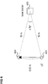
- Figure 4 shows a pedestrian UE maintaining the same orientation while moving at 3Km/h (0.8333 m in 1 second) from a first location 401 to a second location 402, both of which are 10 meters away from a base station 403, which results in an angular change of the line-of-sight path of 4.78° per second.
- a user running an augmented reality or interactive gaming application can rotate the device by a much faster rate, e.g., 90° per 1/10 second.
- the direction and speed of the UE rotation may change rapidly as well.
- subtle and jittery human hand and body movements often subconscious and involuntary, may become significant for high-performance UEs with fine beam granularity.
- UE beam selection needs to consider periods of UE rotations whose angular change is significant with respect to beam training intervals.
- 5G system proposals support beam training intervals in the order of 5 milliseconds, where each training instance may allow testing of a small subset of UE beam directions, often a group in the immediate vicinity of a previously selected direction.
- a base station e.g. corresponding to transmitter 201
- periodically transmits reference signals to a UE e.g. corresponding to receiver 202
- the UE performs a beam search procedure (also referred to as beam training procedure) based on the received reference signals.
- a trained UE beam is used for the rest of the interval (e.g. 5 milliseconds) until the next training (i.e. the next transmission of beam training reference signals), at which a relatively small angular adjustments may be made.
- a UE may be prone to quick and large turns in addition to continuous episodes of sudden step-like rotations.
- a UE rotation of 90° or more in 100 milliseconds are reasonable scenarios for the said high data-rate applications, and continuous jitters may translate to changes in the optimal beam direction in between two beam training instances.
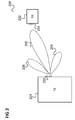
- Figure 5 illustrates an example of a UE rotation and a corresponding change of the best beam direction.
- a left representation 501 the UE is shown with a first (horizontal) orientation while in a right representation 502, assumed to arise from a 90° rotation of the UE during 0.1 second, the UE 502 is shown with a second (vertical) orientation.
- each petal-shape 503 represents a candidate beam.
- a first petal 504 corresponds to an optimally selected beam direction at an initial point in time (time of the UE having the first orientation) and a second petal 505 corresponds to the optimal beam after the 90° UE rotation.
- the UE may obtain a prediction of the best beam direction for the next beamforming instance and use it to (1) preemptively switch to another beam direction, and/or (2) update the search pool of candidate beams, thereby reducing the number of candidates for more efficient search or increase the accuracy of beam selection.
- the UE may base the rotation estimation, i.e. the estimation of the direction and speed of antenna array rotation on a beam history, for example on the selected beams (i.e. beam directions) at the two or more recent beamforming instances.
- the UE When in a training mode, i.e. for a beam training procedure, the UE may for example shift a set of beam directions in the estimated rotation direction by the estimated amount of rotation (e.g. based on the estimated rotation speed). When not in a training mode, i.e. in between two consecutive beam training procedures, the UE may preemptively shift the beam direction according to the estimated rotation.
- beamforming enhancement may for example also be based on rotation estimation by using motion/orientation sensors to first detect whether there are device rotations, displacement, or blockers. For example, if a blocker is detected, the beams are switched to a back-up set corresponding to the second best channel cluster, obtained from a previous global beam training. If displacement is detected both Tx and Rx beam sweeps are initiated. If rotation is detected, Rx beam training is triggered.
- AP rotation may be estimated using orientation sensors and any beam mismatch may be realigned with triggered/periodic beam training.
- the starting point of beam search may be shifted according to the sensor-based rotation estimate.
- rotation estimation may be based on past beam selections (in contrast to measurements by rotation sensors). This provides an economical alternative to a sensor-based approach which requires extra hardware and tight timing budget for sensor information processing. Further, the beam refinement according to the approaches described in the following may not solely rely on beam training and may actively adapt beam directions between trainings according to the rotation estimate. This can provide an advantage in the wide range of communication systems (e.g. 5G) where the scheduled beam training interval may be longer than the time for rotation-induced beam drift to become significant and where device-triggered training is not supported.
- 5G communication systems
- UE rotation may be quantified as the direction and speed of antenna array (e.g. corresponding to directional antenna 204) orientation change, or equivalently, as the shift of the antenna array orientation in azimuth and elevation.
- the estimate may be given as relative angular shifts in azimuth and elevation axes, or it may also be given as the angle and hypotenuse formed by the azimuth and elevation shifts, where the angle corresponds to the direction and the hypotenuse length corresponds to the speed of the rotation.
- a mobile device 109 can face any direction, thus the notion of azimuth and elevation is purely relative to an arbitrary reference orientation of the mobile device 109. This is especially true for handheld devices, where it is preferable to support similar beamforming capabilities, e.g. beam-width and gain, over all three-dimensional directions. Nevertheless, this notion (azimuth and elevation) is useful for describing beamforming methods and is used herein for convenience.
- an antenna array orientation may also be viewed as a device orientation.
- the change of this antenna array orientation is equivalent to the change of a given fixed beam direction at the mobile device (e.g. UE) in a relative sense.
- This rotation estimate may be based on sensor information or based on beam history.
- the estimate may for example be a weighted average of two or more beams that the UE had selected in the previous beam selection opportunities.
- Figure 6 shows an example of the beam-history-based UE rotation estimation.
- Each hexagon 601 represents a distinct beam direction that the UE antenna array can form, and the total set of hexagons represents a projection of all possible three-dimensional beam directions onto a two-dimensional plane.
- the horizontal axis (x-axis) is denoted as azimuth and the vertical axis (y-axis) as elevation.
- Hatched hexagons 602, 603, 604 with indices denote selected beams that are used to deduce the rotation estimate.
- a hexagon 603 with index n - 1 denotes the beam selected at the ( n - 1)-th beam-selection opportunity.
- Arrows 605, 606, 607 at the bottom graphically represent the rotation estimate, which can be interpreted in two ways.
- the angle of the arrow 605 corresponds to the rotation direction and the length of the arrow 605 corresponds to the rotation speed.
- the length of the horizontal arrow 606 denoted as ⁇ x corresponds to the rotation angle in azimuth and the length of the vertical arrow 607 denoted as ⁇ y corresponds to the rotation angle in elevation.
- the UE e.g. a corresponding antenna controller, e.g. part of a transceiver of the UE
- x [ n ] and y [ n ] denote azimuth and elevation angles of the selected beam at
- the estimation starts as soon as two beam selections become available, and it is initialized with a simple difference between the first two selections.
- the set of ⁇ x [ n ] and ⁇ y [ n ] forms a vector equivalent to the thick arrow 605.
- the 1-tap IIR (infinite impulse response) filter given above for rotation estimation is an example. Further embodiments of rotation estimation may use a variety of filtering methods on beam history, such as moving average filter or state-space descriptions (Kalman Filter).
- One generalization of the rotation estimation described above is to use the history of multiple beams, in the case that the UE supports multiple simultaneous beams for multiple-input multiple-output (MIMO) communication, where each of the simultaneous UE beams may be uniquely identified and be associated with a directional antenna, e.g., a phased antenna array.
- MIMO multiple-input multiple-output
- one set of rotation estimates may be formed with each UE beam, and then a final rotation estimate may be formed via a weighted-average of the per-beam azimuth rotation estimates and a weighted-average of the per-beam elevation rotation estimates.
- the weights for the averaging may be constant if each of the multiple simultaneous beams has similar beam quality (e.g. beam width and gain) and can be directed to any desired direction.
- the weights may be different for each UE beam and/or for azimuth and elevation (they may even be zero for particular azimuth or elevation component of some UE beams) if each beam has different beam quality and/or can only be directed to a limited range of angles.
- Such a variable weighting is particularly relevant if, for instance, some of the antenna arrays have highly restricted ranges of beam directions in either azimuth or elevation and/or have coarse angular granularity, as may be the case for the arrays facing the thin sides in a small form-factor hand-held device, e.g., a smartphone.
- the mobile device can use the rotation estimates obtained via either a beam-history-based or sensor-aided estimation approach to refine the set of beam candidates considered for the next beamforming instance.
- two refinement approaches are described in the following.
- the first approach is to adjust the search set of beam candidates and is illustrated in figures 7 and 8 .
- the mobile device may for example use this approach in a beamforming communication system that provides beam training mechanisms whereby the UE may try multiple beams and select one according to an optimization criterion.
- the set of beam candidates to be tried in the next beam training opportunity may be shifted by ⁇ ⁇ ⁇ x [ n ], ⁇ ⁇ y [ n ] ⁇ , where ⁇ is a scaling constant that accounts for any difference in time scale (e.g. observation periodicity) of rotation estimate and beamforming instances.
- the constant ⁇ may also act as a damping factor so that the adjusted search set does not shift too much in a single adjustment and/or includes the most recently used beam.
- Figure 7 shows an example beam search set refinement based on a rotation estimate ⁇ x [ n ], ⁇ y [ n ] ⁇ .
- each hexagon 703 represents a distinct beam direction
- the total set of hexagons in a first representation 701 and the total set of hexagons in a second representation 702 each represent a two-dimensional projection of all beam directions.
- Diagonally hatched hexagons 704, 706 and the cross-hatched hexagon 705, 707 together form, in both representations 701, 702, a set of candidate beams (or, equivalently, candidate beam directions) to search over at a beam training instance (i.e.
- the first representation 701 illustrates a beam search set without refinement based on a rotation estimate
- the second representation 702 represents the beam search set after applying a refinement based on a rotation estimate, given by the azimuth angle difference ⁇ x and the elevation angle difference ⁇ y .
- a refined beam search set 706, 707 may be a shifted version of the initial beam search set 704, 705, shifted by ⁇ ⁇ ⁇ x [ n ], ⁇ ⁇ y [ n ] ⁇ , with a damping factor ⁇ so that the current beam is included in the refined beam search set.
- the shift amount may be quantized as in the example of figure 7 if the communication system specification or the UE implementation necessitates a finite number of fixed beam directions.
- Figure 8 shows another way of refining the beam search set based on the rotation estimate given in figure 7 .
- a first representation 801 illustrates a beam search set without refinement based on a rotation estimate
- a second representation 802 represents the set after applying a refinement based on a rotation estimate.
- the initial search set is reduced by keeping the candidates in the general direction of the rotation and removing the others.
- the aim here is more efficient beam search and reduced cost.
- the second approach of beam refinement is preemptive beam adjustment of a set of beams.
- This approach may for example be used for setting the beam direction when there is no beam search opportunity, e.g. in between two consecutive transmission of reference signals by a base station, i.e. in between two beam search procedures.
- Such scenarios may arise if the communication system supports beamforming for data transmission and reception between two reference signal occurrences for beam training. Without rotation estimates, the beams trained with a reference signal would typically be used until the next reference signal is received, e.g. used for all beamforming instances until the next beam training procedure execution. Aided by a rotation estimate, the UE may gradually shift the beams in between two reference signal occurrences (i.e. beam training procedure occurrences) in the direction of UE rotation.
- Such gradual shift may be a hard hand-off from one quantized direction to another, or it may be a soft handover.
- the latter may be achieved by steering a beam from the default quantized directions, such that its direction may lie between adjacent quantized directions. It may also be achieved by activating two or more simultaneous beams (e.g. using two directional antennas or, alternatively, covering two beam directions by means of a higher beam width), where one is directed to an initial quantized direction and others are directed to adjacent quantized directions toward a target direction.
- Figure 9 shows three examples of a preemptive beam adjustment method.
- each representation 901 to 906 of beam directions by means of hexagons similarly to figures 6 to 8 , are shown, wherein each representation 901 to 906 represents a projection of possible three-dimensional beam directions onto a two-dimensional plane.
- the respective left representation 901, 903, 905 corresponds to the beam selection result after a beam training procedure
- the respective right representation 902, 904, 906 corresponds to a beamforming instance (i.e. an instance of setting a beam direction) after the beam training procedure but before the next beam training procedure.
- a cross-hatched hexagon 907 to 912 or circle 913 represents the respective selected beam
- a dash-filled hexagon 914 to 919 represents the predicted beam direction at the next beam training.
- the first example corresponding to the first two representations 901, 902, shows a hard hand-off from a first beam 907 to a second beam 908,
- the second example corresponding to the second two representations 903, 904 shows a soft handover via beam steering from a first beam 909 to a second beam 913
- the third example corresponding to the third two representations 905, 906 shows a soft handover with two simultaneous beams 911, 912.
- Rx receive
- Tx transmit
- a communication terminal is provided as illustrated in figure 10 .
- Figure 10 shows a mobile communication device 1000.
- the mobile communication device 1000 includes an antenna 1001 which may be set to one of a plurality of main beam directions (e.g. a directional antenna).
- the mobile communication device 1000 includes an estimator 1002 configured to estimate a direction and a speed of a rotational change of the antenna 1001 (in other words a change of an orientation of the antenna 1001), a determiner 1003 configured to adjust at least one reference main beam direction by an amount based on the estimated direction and speed to determine at least one candidate main beam direction of the plurality of main beam directions and a controller 1004 configured to set the antenna to a direction (e.g. in terms of a main beam direction) based on the at least one candidate main beam direction.
- an estimator 1002 configured to estimate a direction and a speed of a rotational change of the antenna 1001 (in other words a change of an orientation of the antenna 1001)
- a determiner 1003 configured to adjust at least one reference main beam direction by an amount based on the estimated direction and speed to determine at least one candidate main beam direction of the plurality of main beam directions
- a controller 1004 configured to set the antenna to a direction (e.g. in terms of a main beam direction) based
- a mobile communication device e.g. a mobile communication terminal (such as a handheld electronic device, e.g. a mobile phone, e.g. a subscriber terminal of a cellular mobile communication network) estimates the speed and direction of its rotation and adapts one or more candidate beam directions based on which it selects or searches a beam direction to be used based on the estimated rotation strength.
- This may include an adaptation of a set of candidate beam directions for a beam search procedure or a beam direction to be set in between two beam search procedure occurrences.
- one of the reference main beam directions may be a current main beam direction currently used by the mobile communication device for communication.
- the mobile communication device may not only be a communication terminal but may also be a communication device which has, for example, base station functionality.
- the one or more candidate beam directions may be a plurality of candidate beam directions of a search set (i.e. in this case "the one or more candidate beam directions" correspond to more than one candidate beam directions), i.e. a set of main beam directions among which the mobile communication device searches for a following main beam direction, e.g. based on the reception of a reference signal.
- the one or more candidate beam directions may also be a single main beam direction to which the mobile communication device sets the antenna (e.g. before the next search).
- the approach of figure 10 may for example allow efficient and accurate beamforming at a mobile device in a wireless communication system. In particular, it allows addressing fast device rotation and its impact on beamforming performance.
- beamforming at a mobile communication device is an emerging technique that is especially relevant with EHF (extremely high frequency, a.k.a. millimeter wave) communication technologies such as 5G and WiGig.
- EHF extreme high frequency, a.k.a. millimeter wave
- 5G and WiGig wireless local area network
- the short wavelength in EHF bands allows the implementation of economical and small antenna arrays with high beamforming gain.
- the components of the mobile communication device may for example be implemented by one or more circuits.
- a “circuit” may be understood as any kind of a logic implementing entity, which may be special purpose circuitry or a processor executing software stored in a memory, firmware, or any combination thereof.
- a “circuit” may be a hard-wired logic circuit or a programmable logic circuit such as a programmable processor, e.g. a microprocessor.
- a “circuit” may also be a processor executing software, e.g. any kind of computer program. Any other kind of implementation of the respective functions which will be described in more detail below may also be understood as a "circuit".
- the mobile communication device 1000 for example carries out a method as illustrated in figure 11 .
- Figure 11 shows a flow diagram 1100 illustrating a method for selecting a beam direction for an antenna (e.g. for controlling or adjusting a beam direction), for example carried out by a communication device. It should be noted that the selection of a beam direction may be seen to be equivalent to the selection of a beam, at least where the beam width is fixed.
- the communication device estimates a direction and a speed of a rotational change of an antenna which may be set to one of a plurality of main beam directions.
- the communication device adjusts at least one reference main beam direction by an amount based on the estimated direction and speed to determine at least one candidate main beam direction of the plurality of main beam directions .
- the communication device sets the antenna to a direction based on the at least one candidate main beam direction.
- Example 1 is a mobile communication device as illustrated in figure 10 .
- Example 2 the subject-matter of Example 1 may optionally include a transceiver coupled to the antenna and configured to maintain a communication link to a radio base station.
- Example 3 the subject-matter of Example 2 may optionally include the controller being configured to control the communication between the transceiver and the radio base station while the antenna is set to the direction based on the at least one candidate main beam direction.
- Example 4 the subject-matter of any one of Examples 1-3 may optionally include the at least one reference main beam direction comprising a current main beam direction of the antenna to which the antenna is currently set.
- Example 5 the subject-matter of Example 4 may optionally include the controller being configured to switch the antenna from a current main beam direction of the antenna, to which the antenna is currently set, to the main beam direction which being based on the at least one candidate main beam direction.
- Example 6 the subject-matter of any one of Examples 1-5 may optionally include the at least one reference main beam direction comprising a main beam direction of the antenna obtained by a beam search procedure based on a reference signal transmitted by a base station.
- Example 7 the subject-matter of any one of Examples 1-6 may optionally include the controller being configured to set the antenna to the main beam direction at a time that depends on the estimated change of orientation of the antenna.
- Example 8 the subject-matter of any one of Examples 1-7 may optionally include the communication link being a radio access link.
- Example 9 the subject-matter of any one of Examples 1-8 may optionally include the at least one reference main beam direction being a set of search candidate beam directions around a current main beam direction.
- Example 10 the subject-matter of Example 9 may optionally include the controller being configured to search a main beam direction of the set of search candidate beam directions and to set the antenna to the main beam direction obtained by the search.
- Example 11 the subject-matter of any one of Examples 1-10 may optionally include the antenna being an antenna array.
- Example 12 the subject-matter of any one of Examples 1-11 may optionally include the estimator being configured to estimate the direction and the speed of the change of the orientation of the antenna based on a set of main beam directions to which the controller has set the antenna.
- Example 13 the subject-matter of Example 12 may optionally include the set of main beam directions being a history of main beam directions comprising two or more main beam directions to which the controller has previously set the antenna.
- Example 14 the subject-matter of any one of Examples 12-13 may optionally include the set of main beam directions comprising a main beam direction to which the antenna is currently set.
- Example 15 the subject-matter of any one of Examples 1-14 may optionally include the controller being configured to perform a beam search procedure based on a reference signal transmitted by a base station with a predetermined periodicity and set the antenna to a direction based on a result of the beam search procedure and the estimator being configured to estimate the direction and the speed of the change of the orientation of the antenna, the determiner being configured to determine the at least one candidate main beam direction of the plurality of main beam directions and the controller being configured to set the antenna to the direction based on the at least one candidate main beam direction after the controller has performed a last beam search procedure and before it performs the next beam search procedure.
- the controller being configured to perform a beam search procedure based on a reference signal transmitted by a base station with a predetermined periodicity and set the antenna to a direction based on a result of the beam search procedure and the estimator being configured to estimate the direction and the speed of the change of the orientation of the antenna
- the determiner being configured to determine the at least one candidate main beam direction of the plurality
- Example 16 the subject-matter of Example 15 may optionally include the at least one reference man beam direction comprising a main beam direction based on a result of the last beam search procedure.
- Example 17 the subject-matter of any one of Examples 1-16 may optionally include a transmitter configured to transmit a message to a base station indicating that the mobile communication device is capable of estimating direction and speed of a rotational change of the antenna.
- Example 18 the subject-matter of any one of Examples 1-17 may optionally further include a sensor configured to measure at least one of a rotation speed, a rotation acceleration and an orientation of the antenna and the estimator being configured to estimate the direction and the speed of a change of the orientation of the antenna based on a measurement by the sensor.
- a sensor configured to measure at least one of a rotation speed, a rotation acceleration and an orientation of the antenna and the estimator being configured to estimate the direction and the speed of a change of the orientation of the antenna based on a measurement by the sensor.
- Example 19 is a base station configured to receive a message from a mobile communication terminal indicating that the mobile communication terminal is capable of estimating direction and speed of a rotational change of its antenna and configured to transmit beam training reference signals to the mobile communication terminal based on the indication.
- Example 20 the subject matter of Example 19 may optionally include the base station being configured to set at least one of a time-frequency density and a periodicity of the transmission of the beam training reference signals based on the indication.
- Example 21 is a method for selecting a beam direction for an antenna as illustrated in figure 11 .
- Example 22 the subject-matter of any one of Examples 21- may optionally include maintaining a communication link to a radio base station by means of the antenna.
- Example 23 the subject-matter of any one of Examples 22- may optionally include controlling the transceiver to perform communication using the antenna set to the direction based on the at least one candidate main beam direction.
- Example 24 the subject-matter of any one of Examples 21-23 may optionally include the at least one reference main beam direction comprising a current main beam direction of the antenna to which the antenna is currently set.
- Example 25 the subject-matter of Example 24 may optionally include switching the antenna from a current main beam direction of the antenna, to which the antenna is currently set, to the main beam direction which being based on the at least one candidate main beam direction.
- Example 26 the subject-matter of any one of Examples 21-25 may optionally include the at least one reference main beam direction comprising a main beam direction of the antenna obtained by a beam search procedure based on a reference signal transmitted by a base station.
- Example 27 the subject-matter of any one of Examples 21-26 may optionally include setting the antenna to the direction at a time that depends on the estimated change of orientation of the antenna.
- Example 28 the subject-matter of any one of Examples 21-27 may optionally include the communication link being a radio access link.
- Example 29 the subject-matter of any one of Examples 21-28 may optionally include the at least one reference main beam direction being a set of search candidate beam directions around a current main beam direction.
- Example 30 the subject-matter of Example 29 may optionally include searching a main beam direction of the set of search candidate beam directions and setting the antenna to the main beam direction obtained by the search.
- Example 31 the subject-matter of any one of Examples 21-30 may optionally include the antenna being an antenna array.
- Example 32 the subject-matter of any one of Examples 21-31 may optionally include estimating the direction and the speed of the change of the orientation of the antenna based on a set of main beam directions to which the antenna has been set.
- Example 33 the subject-matter of any one of Examples 22-32 may optionally include the set of main beam directions being a history of main beam directions comprising two or more main beam directions to which the antenna has previously been set.
- Example 34 the subject-matter of any one of Examples 22-33 may optionally include the set of main beam directions comprising a main beam direction to which the antenna is currently set.
- Example 35 the subject-matter of any one of Examples 21-34 may optionally include performing a beam search procedure based on a reference signal transmitted by a base station with a predetermined periodicity and setting the antenna to a direction based on a result of the beam search procedure, estimating the direction and the speed of the change of the orientation of the antenna, determining the at least one candidate main beam direction of the plurality of main beam directions and setting the antenna to the direction based on the at least one candidate main beam direction after performing a last beam search procedure and before performing the next beam search procedure.
- Example 36 the subject-matter of Example 35 may optionally include the at least one reference man beam direction comprising a main beam direction based on a result of the last beam search procedure.
- Example 37 the subject-matter of any one of Examples 21-36 may optionally include transmitting a message to a base station indicating the capability of estimating direction and speed of a rotational change of the antenna.
- Example 38 the subject-matter of any one of Examples 21-37 may optionally include measuring at least one of a rotation speed, a rotation acceleration and an orientation of the antenna by means of a sensor and estimating the direction and the speed of a change of the orientation of the antenna based on a measurement by the sensor.
- Example 39 is a method for transmitting beam training reference signals comprising receiving a message from a mobile communication terminal indicating that the mobile communication terminal is capable of estimating direction and speed of a rotational change of its antenna and configured to transmit beam training reference signals to the mobile communication terminal based on the indication.
- Example 40 the subject-matter of Example 39 may optionally include setting at least one of a time-frequency density and a periodicity of the transmission of the beam training reference signals based on the indication.
- a method for determining a transmission direction or a reception direction for a communication at a mobile device of a radio communications network comprising estimating a rotation of the orientation of the mobile device and adjusting one or more beam directions (i.e. direction of one or more transmission beams or reception beams or both) based on the rotation estimate.
- the estimate of a rotation of the orientation of the mobile device may for example comprise an angular shift in azimuth and an angular shift in elevation and may include an estimate of the speed of rotation.
- the estimate of a rotation of the orientation of the mobile device is for example an output of a filter function processing at least two beam (transmission/reception) directions taken at different times.
- the adjustment of beam (transmission/reception) directions is for example a scaled and a quantized shift of the target set of beam (transmission/reception) directions, where the shift is the rotation angle estimate of the orientation of the mobile device.
- the adjustment of beam (transmission/reception) directions is for example a reduced subset of the target set of beam (transmission/reception) directions, whereby the subset comprises the candidate directions that are within certain angular offset from one or both of the azimuth angular shift and elevation angular shift of the rotation estimate.
- a system and a method for determining the time-frequency density and periodicity of reference signals for beam training in a radio communications network comprising indicating, by a mobile device, its capability of device rotation estimation and determining, by the base station, the time-frequency density and periodicity of the beam-training reference signals based on the indication.
- Time-frequency density means the density of reference signals in the time-frequency grid (or in time- and frequency-axis), i.e., in other words, time-frequency positions of reference signals.
Landscapes
- Engineering & Computer Science (AREA)
- Computer Networks & Wireless Communication (AREA)
- Signal Processing (AREA)
- Mobile Radio Communication Systems (AREA)
- Radio Transmission System (AREA)
Priority Applications (2)
| Application Number | Priority Date | Filing Date | Title |
|---|---|---|---|
| EP16188358.2A EP3293890A1 (fr) | 2016-09-12 | 2016-09-12 | Dispositif de communication mobile et procédé permettant de sélectionner une direction de faisceau d'une antenne |
| PCT/US2017/045662 WO2018048543A1 (fr) | 2016-09-12 | 2017-08-07 | Dispositif de communication mobile et procédé de sélection d'une direction de faisceau pour une antenne |
Applications Claiming Priority (1)
| Application Number | Priority Date | Filing Date | Title |
|---|---|---|---|
| EP16188358.2A EP3293890A1 (fr) | 2016-09-12 | 2016-09-12 | Dispositif de communication mobile et procédé permettant de sélectionner une direction de faisceau d'une antenne |
Publications (1)
| Publication Number | Publication Date |
|---|---|
| EP3293890A1 true EP3293890A1 (fr) | 2018-03-14 |
Family
ID=56926044
Family Applications (1)
| Application Number | Title | Priority Date | Filing Date |
|---|---|---|---|
| EP16188358.2A Ceased EP3293890A1 (fr) | 2016-09-12 | 2016-09-12 | Dispositif de communication mobile et procédé permettant de sélectionner une direction de faisceau d'une antenne |
Country Status (2)
| Country | Link |
|---|---|
| EP (1) | EP3293890A1 (fr) |
| WO (1) | WO2018048543A1 (fr) |
Cited By (8)
| Publication number | Priority date | Publication date | Assignee | Title |
|---|---|---|---|---|
| WO2019226028A1 (fr) | 2018-05-25 | 2019-11-28 | Samsung Electronics Co., Ltd. | Procédés de génération de livre de codes de faisceau pour terminaux 5g |
| WO2019240446A1 (fr) | 2018-06-11 | 2019-12-19 | Samsung Electronics Co., Ltd. | Procédés d'adaptation de formation de faisceau spécifique à un terminal pour systèmes sans fil avancés |
| EP3734857A4 (fr) * | 2018-02-08 | 2021-01-20 | Samsung Electronics Co., Ltd. | Procédé d'opération de faisceau et dispositif au niveau d'un terminal d'un système de communication a formation de faisceau |
| WO2021115551A1 (fr) * | 2019-12-09 | 2021-06-17 | Telefonaktiebolaget Lm Ericsson (Publ) | Sélection de faisceau candidat pour un dispositif terminal |
| CN113812192A (zh) * | 2019-05-10 | 2021-12-17 | 瑞典爱立信有限公司 | 用于无线电波束确定的方法和设备 |
| KR20220044650A (ko) * | 2020-10-02 | 2022-04-11 | 삼성전자주식회사 | 안테나 오정렬이 있는 가시선 다중 입력 및 다중 출력 통신을 위한 방법 및 시스템 |
| WO2023191674A1 (fr) * | 2022-03-31 | 2023-10-05 | Telefonaktiebolaget Lm Ericsson (Publ) | Procédé et dispositif sans fil de formation de faisceau à l'aide d'un décalage doppler pour estimer des angles de départ ou d'arrivée de signaux |
| CN118140431A (zh) * | 2021-10-27 | 2024-06-04 | 高通股份有限公司 | 管理针对多订制无线设备的波束选择 |
Families Citing this family (9)
| Publication number | Priority date | Publication date | Assignee | Title |
|---|---|---|---|---|
| CN115066807A (zh) * | 2020-01-30 | 2022-09-16 | 哲库科技有限公司 | 利用自适应波束图的天线波束成形控制 |
| US11463140B2 (en) | 2020-05-01 | 2022-10-04 | Fujikura Ltd. | Wireless communication device |
| US11450957B2 (en) * | 2020-05-01 | 2022-09-20 | Fujikura Ltd. | Wireless communication device |
| CN114449099B (zh) * | 2020-11-02 | 2023-07-28 | 华为技术有限公司 | 一种设备方位调整的方法、终端设备和可读存储介质 |
| CN114641009B (zh) * | 2020-12-16 | 2023-06-16 | 中国联合网络通信集团有限公司 | 波束扫描方法和装置 |
| CN116828394B (zh) * | 2022-03-30 | 2024-02-20 | 南方科技大学 | 追踪通信方法、追踪通信装置、电子设备以及存储介质 |
| CN115065981B (zh) * | 2022-08-16 | 2022-11-01 | 新华三技术有限公司 | 一种波束追踪方法及装置 |
| US20260046170A1 (en) * | 2022-09-23 | 2026-02-12 | Qualcomm Incorporated | Radio frequency reflection arrays having at least one antenna element |
| WO2025102606A1 (fr) * | 2023-11-14 | 2025-05-22 | Huawei Technologies Co., Ltd. | Appareil, procédé et support de stockage lisible à des fins de communication |
Citations (5)
| Publication number | Priority date | Publication date | Assignee | Title |
|---|---|---|---|---|
| US20130017836A1 (en) * | 2011-07-15 | 2013-01-17 | Samsung Electronics Co., Ltd. | Apparatus and method for beam locking in a wireless communication system |
| US20130040682A1 (en) * | 2011-08-10 | 2013-02-14 | Samsung Electronics Co., Ltd. | Apparatus and method for beam locking in wireless communication system |
| US20150264583A1 (en) * | 2014-03-12 | 2015-09-17 | Telefonaktiebolaget L M Ericssson (Publ) | Antenna Beam Control |
| US20160065286A1 (en) * | 2014-08-27 | 2016-03-03 | Intel IP Corporation | Apparatus, system and method of beam tracking |
| US20160198474A1 (en) * | 2015-01-06 | 2016-07-07 | Qualcomm Incorporated | Techniques for beam shaping at a millimeter wave base station and a wireless device and fast antenna subarray selection at a wireless device |
Family Cites Families (3)
| Publication number | Priority date | Publication date | Assignee | Title |
|---|---|---|---|---|
| US20070087695A1 (en) * | 2005-10-17 | 2007-04-19 | Searete Llc, A Limited Liability Corporation Of The State Of Delaware | Mobile directional antenna |
| US9147935B2 (en) * | 2011-08-10 | 2015-09-29 | Qualcomm Incorporated | Maintenance of mobile device RF beam |
| KR102029102B1 (ko) * | 2012-11-19 | 2019-11-11 | 삼성전자주식회사 | 빔포밍 시스템에서 빔 방향 선택 방법 및 장치 |
-
2016
- 2016-09-12 EP EP16188358.2A patent/EP3293890A1/fr not_active Ceased
-
2017
- 2017-08-07 WO PCT/US2017/045662 patent/WO2018048543A1/fr not_active Ceased
Patent Citations (5)
| Publication number | Priority date | Publication date | Assignee | Title |
|---|---|---|---|---|
| US20130017836A1 (en) * | 2011-07-15 | 2013-01-17 | Samsung Electronics Co., Ltd. | Apparatus and method for beam locking in a wireless communication system |
| US20130040682A1 (en) * | 2011-08-10 | 2013-02-14 | Samsung Electronics Co., Ltd. | Apparatus and method for beam locking in wireless communication system |
| US20150264583A1 (en) * | 2014-03-12 | 2015-09-17 | Telefonaktiebolaget L M Ericssson (Publ) | Antenna Beam Control |
| US20160065286A1 (en) * | 2014-08-27 | 2016-03-03 | Intel IP Corporation | Apparatus, system and method of beam tracking |
| US20160198474A1 (en) * | 2015-01-06 | 2016-07-07 | Qualcomm Incorporated | Techniques for beam shaping at a millimeter wave base station and a wireless device and fast antenna subarray selection at a wireless device |
Cited By (15)
| Publication number | Priority date | Publication date | Assignee | Title |
|---|---|---|---|---|
| EP3734857A4 (fr) * | 2018-02-08 | 2021-01-20 | Samsung Electronics Co., Ltd. | Procédé d'opération de faisceau et dispositif au niveau d'un terminal d'un système de communication a formation de faisceau |
| US11374643B2 (en) | 2018-02-08 | 2022-06-28 | Samsung Electronics Co., Ltd. | Beam operation method and device at terminal of beamforming communication system |
| EP3785377A4 (fr) * | 2018-05-25 | 2021-06-23 | Samsung Electronics Co., Ltd. | Procédés de génération de livre de codes de faisceau pour terminaux 5g |
| CN112075033A (zh) * | 2018-05-25 | 2020-12-11 | 三星电子株式会社 | 5g终端的波束码本生成方法 |
| WO2019226028A1 (fr) | 2018-05-25 | 2019-11-28 | Samsung Electronics Co., Ltd. | Procédés de génération de livre de codes de faisceau pour terminaux 5g |
| CN112075033B (zh) * | 2018-05-25 | 2024-02-09 | 三星电子株式会社 | 5g终端的波束码本生成方法 |
| EP3782301A4 (fr) * | 2018-06-11 | 2021-06-09 | Samsung Electronics Co., Ltd. | Procédés d'adaptation de formation de faisceau spécifique à un terminal pour systèmes sans fil avancés |
| US11108473B2 (en) | 2018-06-11 | 2021-08-31 | Samsung Electronics Co., Ltd. | Methods for terminal-specific beamforming adaptation for advanced wireless systems |
| WO2019240446A1 (fr) | 2018-06-11 | 2019-12-19 | Samsung Electronics Co., Ltd. | Procédés d'adaptation de formation de faisceau spécifique à un terminal pour systèmes sans fil avancés |
| CN113812192A (zh) * | 2019-05-10 | 2021-12-17 | 瑞典爱立信有限公司 | 用于无线电波束确定的方法和设备 |
| WO2021115551A1 (fr) * | 2019-12-09 | 2021-06-17 | Telefonaktiebolaget Lm Ericsson (Publ) | Sélection de faisceau candidat pour un dispositif terminal |
| US11973565B2 (en) | 2019-12-09 | 2024-04-30 | Telefonaktiebolaget Lm Ericsson (Publ) | Candidate beam selection for a terminal device |
| KR20220044650A (ko) * | 2020-10-02 | 2022-04-11 | 삼성전자주식회사 | 안테나 오정렬이 있는 가시선 다중 입력 및 다중 출력 통신을 위한 방법 및 시스템 |
| CN118140431A (zh) * | 2021-10-27 | 2024-06-04 | 高通股份有限公司 | 管理针对多订制无线设备的波束选择 |
| WO2023191674A1 (fr) * | 2022-03-31 | 2023-10-05 | Telefonaktiebolaget Lm Ericsson (Publ) | Procédé et dispositif sans fil de formation de faisceau à l'aide d'un décalage doppler pour estimer des angles de départ ou d'arrivée de signaux |
Also Published As
| Publication number | Publication date |
|---|---|
| WO2018048543A1 (fr) | 2018-03-15 |
Similar Documents
| Publication | Publication Date | Title |
|---|---|---|
| EP3293890A1 (fr) | Dispositif de communication mobile et procédé permettant de sélectionner une direction de faisceau d'une antenne | |
| CN111480303B (zh) | 基于移动传感器的波束转向控制装置和方法 | |
| US8306572B2 (en) | Communication control method, communication system and communication control apparatus | |
| EP2979410B1 (fr) | Estimation de canal dans les communications mobiles avec beamforming | |
| EP3602817B1 (fr) | Systèmes, procédés et dispositifs de sélection de faisceau dans un système de communication sans fil | |
| EP3586451B1 (fr) | Appareil pour configurer des faisceaux de signaux de référence sur la base d'une précision de localisation d'équipement utilisateur | |
| CN109690963B (zh) | 无线电通信设备的波束方向选择 | |
| EP3625895B1 (fr) | Procédé de réalisation d'une communication de données sans fil assistée par radar | |
| US8811907B2 (en) | Control method of radio communication system, radio communication system, and radio communication apparatus | |
| US20140070995A1 (en) | Communication device, communication control method, and program | |
| KR20180059306A (ko) | 안테나를 포함하는 장치 및 그 제어 방법 | |
| US11444677B2 (en) | Communication devices for efficient beam management | |
| WO2021260047A1 (fr) | Dispositifs réfléchissants reconfigurables dépendants de l'angle d'arrivée | |
| CN106034307A (zh) | 一种到达角波束赋形权值估计方法和装置 | |
| US20180248610A1 (en) | Methods for radio communication and communication devices | |
| CN116567692A (zh) | 通信方法与通信装置 | |
| CN112020077A (zh) | 通信方法及装置 | |
| WO2018000405A1 (fr) | Dispositif de communication et procédé destinés à sélectionner une direction de faisceau | |
| WO2022187801A1 (fr) | Apprentissage de vecteur de phase pour une communication activée par dispositif à changement de phase adaptatif | |
| US10256891B2 (en) | Mobile communication device and method for selecting a beam direction | |
| CN108141266A (zh) | 通信装置和操作通信装置的方法 | |
| KR20090042859A (ko) | 무선 통신 장치 및 무선 통신 방법 | |
| EP4583423A1 (fr) | Procédé de fonctionnement d'un équipement utilisateur pour la formation de faisceau dans un système de communication sans fil et équipement utilisateur associé | |
| WO2020101756A2 (fr) | Procédé et appareil de sélection de groupe de réseaux d'antennes et de sélection de réseau d'antennes pour des communications de dispositif | |
| JP2014179776A (ja) | 無線通信装置、制御方法及び制御プログラム |
Legal Events
| Date | Code | Title | Description |
|---|---|---|---|
| PUAI | Public reference made under article 153(3) epc to a published international application that has entered the european phase |
Free format text: ORIGINAL CODE: 0009012 |
|
| STAA | Information on the status of an ep patent application or granted ep patent |
Free format text: STATUS: REQUEST FOR EXAMINATION WAS MADE |
|
| 17P | Request for examination filed |
Effective date: 20160912 |
|
| AK | Designated contracting states |
Kind code of ref document: A1 Designated state(s): AL AT BE BG CH CY CZ DE DK EE ES FI FR GB GR HR HU IE IS IT LI LT LU LV MC MK MT NL NO PL PT RO RS SE SI SK SM TR |
|
| AX | Request for extension of the european patent |
Extension state: BA ME |
|
| STAA | Information on the status of an ep patent application or granted ep patent |
Free format text: STATUS: EXAMINATION IS IN PROGRESS |
|
| 17Q | First examination report despatched |
Effective date: 20190211 |
|
| RAP1 | Party data changed (applicant data changed or rights of an application transferred) |
Owner name: APPLE INC. |
|
| STAA | Information on the status of an ep patent application or granted ep patent |
Free format text: STATUS: THE APPLICATION HAS BEEN REFUSED |
|
| 18R | Application refused |
Effective date: 20211002 |