EP3294596B1 - Bremssystem - Google Patents
Bremssystem Download PDFInfo
- Publication number
- EP3294596B1 EP3294596B1 EP16733188.3A EP16733188A EP3294596B1 EP 3294596 B1 EP3294596 B1 EP 3294596B1 EP 16733188 A EP16733188 A EP 16733188A EP 3294596 B1 EP3294596 B1 EP 3294596B1
- Authority
- EP
- European Patent Office
- Prior art keywords
- braking
- fact
- trailer
- command means
- command
- Prior art date
- Legal status (The legal status is an assumption and is not a legal conclusion. Google has not performed a legal analysis and makes no representation as to the accuracy of the status listed.)
- Active
Links
Images
Classifications
-
- B—PERFORMING OPERATIONS; TRANSPORTING
- B60—VEHICLES IN GENERAL
- B60T—VEHICLE BRAKE CONTROL SYSTEMS OR PARTS THEREOF; BRAKE CONTROL SYSTEMS OR PARTS THEREOF, IN GENERAL; ARRANGEMENT OF BRAKING ELEMENTS ON VEHICLES IN GENERAL; PORTABLE DEVICES FOR PREVENTING UNWANTED MOVEMENT OF VEHICLES; VEHICLE MODIFICATIONS TO FACILITATE COOLING OF BRAKES
- B60T7/00—Brake-action initiating means
- B60T7/02—Brake-action initiating means for personal initiation
- B60T7/08—Brake-action initiating means for personal initiation hand actuated
-
- B—PERFORMING OPERATIONS; TRANSPORTING
- B60—VEHICLES IN GENERAL
- B60T—VEHICLE BRAKE CONTROL SYSTEMS OR PARTS THEREOF; BRAKE CONTROL SYSTEMS OR PARTS THEREOF, IN GENERAL; ARRANGEMENT OF BRAKING ELEMENTS ON VEHICLES IN GENERAL; PORTABLE DEVICES FOR PREVENTING UNWANTED MOVEMENT OF VEHICLES; VEHICLE MODIFICATIONS TO FACILITATE COOLING OF BRAKES
- B60T7/00—Brake-action initiating means
- B60T7/02—Brake-action initiating means for personal initiation
- B60T7/08—Brake-action initiating means for personal initiation hand actuated
- B60T7/10—Disposition of hand control
- B60T7/102—Disposition of hand control by means of a tilting lever
-
- B—PERFORMING OPERATIONS; TRANSPORTING
- B60—VEHICLES IN GENERAL
- B60T—VEHICLE BRAKE CONTROL SYSTEMS OR PARTS THEREOF; BRAKE CONTROL SYSTEMS OR PARTS THEREOF, IN GENERAL; ARRANGEMENT OF BRAKING ELEMENTS ON VEHICLES IN GENERAL; PORTABLE DEVICES FOR PREVENTING UNWANTED MOVEMENT OF VEHICLES; VEHICLE MODIFICATIONS TO FACILITATE COOLING OF BRAKES
- B60T7/00—Brake-action initiating means
- B60T7/02—Brake-action initiating means for personal initiation
- B60T7/08—Brake-action initiating means for personal initiation hand actuated
- B60T7/10—Disposition of hand control
- B60T7/102—Disposition of hand control by means of a tilting lever
- B60T7/104—Disposition of hand control by means of a tilting lever with a locking mechanism
-
- B—PERFORMING OPERATIONS; TRANSPORTING
- B60—VEHICLES IN GENERAL
- B60T—VEHICLE BRAKE CONTROL SYSTEMS OR PARTS THEREOF; BRAKE CONTROL SYSTEMS OR PARTS THEREOF, IN GENERAL; ARRANGEMENT OF BRAKING ELEMENTS ON VEHICLES IN GENERAL; PORTABLE DEVICES FOR PREVENTING UNWANTED MOVEMENT OF VEHICLES; VEHICLE MODIFICATIONS TO FACILITATE COOLING OF BRAKES
- B60T7/00—Brake-action initiating means
- B60T7/02—Brake-action initiating means for personal initiation
- B60T7/08—Brake-action initiating means for personal initiation hand actuated
- B60T7/10—Disposition of hand control
- B60T7/102—Disposition of hand control by means of a tilting lever
- B60T7/104—Disposition of hand control by means of a tilting lever with a locking mechanism
- B60T7/105—Disposition of hand control by means of a tilting lever with a locking mechanism the lock being released by means of a push button
-
- B—PERFORMING OPERATIONS; TRANSPORTING
- B60—VEHICLES IN GENERAL
- B60T—VEHICLE BRAKE CONTROL SYSTEMS OR PARTS THEREOF; BRAKE CONTROL SYSTEMS OR PARTS THEREOF, IN GENERAL; ARRANGEMENT OF BRAKING ELEMENTS ON VEHICLES IN GENERAL; PORTABLE DEVICES FOR PREVENTING UNWANTED MOVEMENT OF VEHICLES; VEHICLE MODIFICATIONS TO FACILITATE COOLING OF BRAKES
- B60T7/00—Brake-action initiating means
- B60T7/02—Brake-action initiating means for personal initiation
- B60T7/08—Brake-action initiating means for personal initiation hand actuated
- B60T7/10—Disposition of hand control
- B60T7/107—Disposition of hand control with electrical power assistance
-
- B—PERFORMING OPERATIONS; TRANSPORTING
- B60—VEHICLES IN GENERAL
- B60T—VEHICLE BRAKE CONTROL SYSTEMS OR PARTS THEREOF; BRAKE CONTROL SYSTEMS OR PARTS THEREOF, IN GENERAL; ARRANGEMENT OF BRAKING ELEMENTS ON VEHICLES IN GENERAL; PORTABLE DEVICES FOR PREVENTING UNWANTED MOVEMENT OF VEHICLES; VEHICLE MODIFICATIONS TO FACILITATE COOLING OF BRAKES
- B60T7/00—Brake-action initiating means
- B60T7/12—Brake-action initiating means for automatic initiation; for initiation not subject to will of driver or passenger
- B60T7/20—Brake-action initiating means for automatic initiation; for initiation not subject to will of driver or passenger specially for trailers, e.g. in case of uncoupling of or overrunning by trailer
-
- B—PERFORMING OPERATIONS; TRANSPORTING
- B60—VEHICLES IN GENERAL
- B60T—VEHICLE BRAKE CONTROL SYSTEMS OR PARTS THEREOF; BRAKE CONTROL SYSTEMS OR PARTS THEREOF, IN GENERAL; ARRANGEMENT OF BRAKING ELEMENTS ON VEHICLES IN GENERAL; PORTABLE DEVICES FOR PREVENTING UNWANTED MOVEMENT OF VEHICLES; VEHICLE MODIFICATIONS TO FACILITATE COOLING OF BRAKES
- B60T7/00—Brake-action initiating means
- B60T7/12—Brake-action initiating means for automatic initiation; for initiation not subject to will of driver or passenger
- B60T7/20—Brake-action initiating means for automatic initiation; for initiation not subject to will of driver or passenger specially for trailers, e.g. in case of uncoupling of or overrunning by trailer
- B60T7/203—Brake-action initiating means for automatic initiation; for initiation not subject to will of driver or passenger specially for trailers, e.g. in case of uncoupling of or overrunning by trailer with automatic brake release or reduction in case of reverse travel, e.g. by means of mechanisms mounted on the draw bar
Definitions
- the present invention relates to a braking device.
- connection device shall be interposed having a pair of male joints able to be inserted inside a pair of relative female joints as well as an electrical connection to control the braking system of the trailer and to transmit any alarm signals from the trailer to the towing vehicle.
- the female joints are connectable to a control line for supplying the braking system of the trailer and to an additional line, respectively, for deactivating the automatic and/or parking brake of the trailer itself.
- the braking phases of a vehicle are generally three in number, i.e. the service braking, which occurs in normal operating conditions of the vehicle, the parking braking, i.e. when the vehicle is stationary in the same position, and the emergency braking.
- the main aim of the present invention is to provide a braking device that allows to meet with the regulatory requirements by means of a solution which is simple from a constructive point of view and of reliable operation.
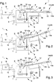
- Figures 1 to 3 are schematic representations of a device according to the invention in three different operating conditions.
- reference number 1 globally indicates a braking device.
- the device 1 comprises a base body 2, associable with the chassis of a towing vehicle, and at least a trailer-brake valve 10 able to adjust the pressure along a control line 7 connectable to the braking system of the trailer and along an additional line 11 operatively connected to the automatic and/or parking brake (not shown in the figures) of the trailer.
- a control line 7 connectable to the braking system of the trailer and along an additional line 11 operatively connected to the automatic and/or parking brake (not shown in the figures) of the trailer.
- the additional line 11 is pressurized the automatic and/or parking brake of the trailer is deactivated, while when the pressure along it goes to zero the automatic and/or parking brake is activated.
- the device 1 further comprises first command means 3 associable with the parking brake of a towing vehicle (not shown in the figures) and activatable to operate the same, and second command means 5 connectable to the trailer-brake valve 10 and able to adjust the pressure along the control line 7. More in detail, the second command means 5 are activatable to send the working fluid under pressure along the control line 7, through the trailer-brake valve 10, and so operate the service braking of the trailer.
- the device 1 also comprises a lever 12 which has at least a first portion 12a hinged to the body 2 around a first axis of rotation X and at least a second portion 12b, graspable by an operator, hinged to the first portion itself around a second axis of rotation Y.
- the first portion 12a is associated with the first command means 3 and is movable between a rest position, in which the first command means 3 are deactivated, and at least a braking position, in which it is rotated with respect to the rest position and the first command means 3 are activated.
- the first portion 12a has a plurality of braking positions among which it moves continuously by applying a gradually increasing force on the first command means 3.
- Locking means 13 of the first portion 12a are also provided in the braking position. More particularly, the locking means 13 are able to keep the first portion 12a in the braking position reached from time to time and are removable by means of a special command 14 to enable the return of the first portion itself to the rest position.
- the locking means 13 are of the type of a ratchet lever and the command 14 is of the type of a button 14a operable in contrast with elastic means 15, e.g. of the type of a spring, to lift the lever and disengage it from the teeth of the ratchet.
- the first command means 3 are of the mechanical type.
- the first command means 3 comprise at least a first cable of flexible and inextensible type, associated with the first portion 12a, which is able to pull the first cable following its rotation from the rest position towards the braking position.
- the second portion 12b is in turn associated with the second command means 5 and is movable between a rest position, in which the second command means themselves are deactivated, and at least a braking position, in which the second portion itself is rotated with respect to the rest position and the second command means 5 are activated so as to operate the service braking of the trailer.
- both the second portion 12b i.e. the lifting thereof from the rest position
- both the second portion itself and the first portion 12a move to a respective braking position by rotating around their respective axes X and Y.
- the rotation of the second portion 12b around the second axis Y in fact involves the exercise of a force on the first portion 12a through the relative hinging axis, which causes the rotation thereof around the first axis X.
- This operating condition corresponds to an emergency condition, shown in Figure 2 , following which both the parking brake of the towing vehicle and the service braking of the trailer are activated.
- This operating condition corresponds to the parking condition, shown in Figure 3 , in which the parking brake of the towing vehicle is activated and the service braking of the trailer is deactivated.
- the second command means 5 are of the mechanical type and comprise at least a second cable 18 flexible and inextensible associated with the second portion 12b, which is able to pull the second cable 18 following its rotation towards the braking position, and elastic means 19 able to counteract such rotation of the second portion 12b. Even in this case, as the second portion 12b rotates around the relative second axis Y away from the rest position, the tractive force increases exerted on the second cable 18.
- the second command means 5 are of the fluid-operated type and comprise at least a fluid-operated cylinder communicating with the trailer-brake valve 10 via a driving line.
- the second portion 12b is thus able to move the piston of the cylinder, it is hinged to, following the rotation thereof around the second axis Y.
- the pressure of the working fluid also increases along the driving line.
- the pressure along the driving line and the tractive force exerted by the first portion 12a on the first cable 3 are therefore related to each other.
- the device 1 also comprises third command means 20 operatively connected to the trailer-brake valve 10 and which are able to control the pressure of the working fluid along the additional line 11 to manage the state of the automatic and/or parking brake the trailer.
- the third command means 20 are operable between an active position, in which they maintain the working fluid under pressure along the additional line 11 to maintain deactivated the automatic and/or parking brake of the trailer, and an inactive position, in which they set to zero the pressure of the working fluid along the additional line 11 so as to activate the automatic and/or parking brake itself.
- the third command means 20 are of the electrical type and comprise an electrical circuit 6 connected to a power source 9. More in detail, the electrical circuit 6 is connected to a solenoid 16 in turn operatively connected to the trailer-brake valve 10. Following the flow of current along the electrical circuit 6, the solenoid 16 is activated allowing the flow of the working fluid along the additional line 11, while when the flow of current is interrupted, the solenoid 16 switches to the inactive state and the trailer-brake valve 10 puts the additional line 11 in communication with the discharge thus causing the activation of the automatic and/or parking brake of the trailer.
- the power source 9 can be composed, e.g., of the power battery of the towing vehicle.
- the device 1 also comprises first and second activation means 25, 26, each movable between a relative first and a relative second work position in which they activate and deactivate, respectively the third command means 20.
- the first activation means 25 are able to interact with the first portion 12a and move from the first to the second work position following the movement of the first portion 12a from the rest position to a braking position.
- the first portion 12a maintains, in its rest position, the first activation means 25 in the relative first work position and first elastic means 27 are provided able to push the first activation means 25 towards the relative second work position following the displacement of the first portion 12a to the braking position.
- Manual means 28 are also provided and operable by an operator to move the second activation means 26 from the second to the first work position.
- the manual means 28 correspond to the aforementioned command 14, i.e. they are associated with the second portion 12b and comprise the button 14a operable in contrast to the elastic means 15, where the button 14a is associated with a thrust element 14b, e.g. of the type of a metal rod or the like, able to interact with the second activation means 26. Therefore, the activation of the command 14 causes both the removal of the locking means 13 and the displacement of the second activation means 26 to the relative first work position.
- the second activation means 26 are located, in normal operating conditions (i.e. in any condition of use in which the manual means 28 are deactivated), in the relative second work position and are moved to the first work position following the operation of the manual means 28 by the operator.
- the second activation means 26 move from the second to the first work position in contrast to second elastic means 29.
- the first and the second activation means 25 and 26 comprise a first and a second switch, respectively, able to close the electrical circuit 6 in the first work position and to open it in the second work position.
- the first portion 12a ( Figure 2 ) is also lifted at the same time, whereby the parking brake of the towing vehicle and the service braking of the trailer are activated.
- the displacement of the first portion 12a from the rest position also causes the displacement of the first switch 25 from the first to the second work position, thus opening the electrical circuit 6 and interrupting the current flow arriving to the solenoid 16.
- the operator maintains the button 14a pressed and moves the second switch 26 from the second to the first work position, in contrast to the second elastic means 29 so as to transmit current to the solenoid 16 and maintain the automatic and/or parking brake of the trailer deactivated.
- the third command means 20 are deactivated because both the first and the second switch 25, 26 are located in the relative second work position, whereby the circuit 6 is not crossed by any current and, consequently, the trailer-brake valve 10 discharges the additional line 11 thus activating the automatic and/or parking brake of the trailer.
- the presence of an electrical circuit connected to the multifunction valve for controlling the pressure along the additional line and of two switches connected to the circuit itself, one of which is able to interact with the first portion of the lever and the other manually operable by the operator, allow to control in an easy and practical manner the activation and deactivation of the automatic and/or parking brake of the trailer.
Landscapes
- Engineering & Computer Science (AREA)
- Transportation (AREA)
- Mechanical Engineering (AREA)
- Regulating Braking Force (AREA)
- Braking Systems And Boosters (AREA)
- Valve Device For Special Equipments (AREA)
- Power Steering Mechanism (AREA)
- Braking Arrangements (AREA)
Claims (12)
- Bremsvorrichtung (1), umfassend:- einen Grundkörper (2), der dem Fahrgestell eines Zugfahrzeugs zugeordnet werden kann;- wenigstens ein Anhänger-Bremsventil (10), das in der Lage ist, den Druck entlang einer Steuerleitung (7), die mit dem Bremssystem eines Anhängers verbindbar ist, und entlang einer zusätzlichen Leitung (11), die betriebsfähig mit der Automatik- und/oder Parkbremse des Anhängers selbst verbindbar ist, anzupassen;- erste Kommandoeinrichtungen (3), die wenigstens der Parkbremse des Zugfahrzeugs zugeordnet werden können und die aktivierbar sind, um dieselbe zu betätigen;- zweite Kommandoeinrichtungen (5), die betriebsfähig mit dem Anhänger-Bremsventil (10) verbunden sind und aktivierbar sind, um ein Arbeitsmedium unter Druck entlang der Steuerleitung (7) zu senden und um die Bremse des Anhängers zu betätigen;dadurch gekennzeichnet, dass es ferner umfasst:- einen Hebel (12), umfassend wenigstens einen ersten Abschnitt (12a), der am Körper (2) um eine erste Drehachse (X) angelenkt ist, der den ersten Kommandoeinrichtungen (3) zugeordnet ist und zwischen einer Ruhestellung und wenigstens einer Bremsstellung, in der die ersten Kommandoeinrichtungen selbst jeweils deaktiviert und aktiviert sind, beweglich ist, wobei abnehmbare Verriegelungseinrichtungen (13) des ersten Abschnitts (12a) in der Bremsstellung vorgesehen sind, und wenigstens einen zweiten Abschnitt (12b), der von einem Bediener greifbar ist, der am ersten Abschnitt (12a) um eine zweite Drehachse (Y) angelenkt ist, den zweiten Kommandoeinrichtungen (5) zugeordnet ist und zwischen einer Ruhestellung und wenigstens einer Bremsstellung, in der die zweiten Kommandoeinrichtungen (5) jeweils deaktiviert und aktiviert sind, beweglich ist; wobei nach der Betätigung des zweiten Abschnitts (12b) sich der Letztere und der erste Abschnitt (12a) in eine jeweilige Bremsstellung bewegen, indem sie um ihre jeweiligen Achsen (X, Y) rotieren, während nach dem Lösen des zweiten Abschnitts (12b) der Letztere in seine Ruhestellung zurückkehrt und der erste Abschnitt (12a) aufgrund der Verriegelungseinrichtungen (13) ortsfest in der Bremsstellung verbleibt;- dritte Kommandoeinrichtungen (20), die betriebsfähig mit dem Anhänger-Bremsventil (10) verbunden sind und zwischen einer aktiven Stellung, in der sie das Arbeitsmedium entlang der zusätzlichen Leitung (11) unter Druck halten, um die Automatik- und/oder Parkbremse des Anhängers deaktiviert zu halten, und einer inaktiven Stellung, in der sie den Druck des Arbeitsmediums entlang der zusätzlichen Leitung (11) auf Null setzen, um die Automatik- und/oder Parkbremse zu aktivieren, betreibbar sind;- erste und zweite Aktivierungseinrichtungen (25, 26), die jeweils zwischen einer relativen ersten und einer relativen zweiten Arbeitsposition, in der sie die dritten Kommandoeinrichtungen (20) jeweils aktivieren und deaktivieren, beweglich sind, wobei die ersten Aktivierungseinrichtungen (25) von der ersten in die zweite Arbeitsposition bewegt werden, nachdem der erste Abschnitt (12a) aus der Ruhestellung in eine Bremsstellung versetzt wurde, und wobei manuelle Einrichtungen (28) vorgesehen sind, die von einem Bediener betreibbar sind, um die zweiten Aktivierungseinrichtungen (26) von der zweiten in die erste Arbeitsposition zu bewegen.
- Vorrichtung (1) nach Anspruch 1, dadurch gekennzeichnet, dass die ersten Kommandoeinrichtungen (3) von mechanischem Typ sind und wenigstens ein erstes unausdehnbares Kabel umfassen, das dem ersten Abschnitt (12a) zugeordnet ist, wobei der Letztere in der Lage ist, das erste Kabel nach seiner Drehung in Richtung der Parkstellung zu ziehen.
- Vorrichtung (1) nach Anspruch 1 oder 2, dadurch gekennzeichnet, dass die zweiten Kommandoeinrichtungen (5) von mechanischem Typ sind.
- Vorrichtung (1) nach Anspruch 3, dadurch gekennzeichnet, dass die zweiten Kommandoeinrichtungen (5) ein zweites unausdehnbares Kabel (18) umfassen, das dem zweiten Abschnitt (12b) zugeordnet ist, wobei der Letztere in der Lage ist, das zweite Kabel (18) nach seiner Drehung in Richtung der Bremsstellung zu ziehen, und dadurch, dass sie elastische Einrichtungen (19) umfasst, die in der Lage sind, der Drehung des zweiten Abschnitts (12b) in Richtung der Bremsstellung entgegenzuwirken.
- Vorrichtung (1) nach Anspruch 1 oder 2, dadurch gekennzeichnet, dass die zweiten Kommandoeinrichtungen (5) wenigstens einen mit einem Medium betriebenen Zylinder und wenigstens eine Antriebsleitung, die auf einer Seite mit dem Zylinder selbst und auf der anderen mit dem Anhänger-Bremsventil (10) kommuniziert, umfassen, wobei der zweite Abschnitt (12b) in der Lage ist, den Kolben des Zylinders nach seiner Drehung um die zweite Achse (Y) zu bewegen.
- Vorrichtung (1) nach einem oder mehreren der vorstehenden Ansprüche, dadurch gekennzeichnet, dass die dritten Kommandoeinrichtungen (20) von mechanischem Typ sind.
- Vorrichtung (1) nach Anspruch 6, dadurch gekennzeichnet, dass die dritten Kommandoeinrichtungen (20) eine elektrische Schaltung (6) umfassen, die mit einer Stromquelle (9) verbunden ist, und dadurch, dass die ersten und zweiten Aktivierungseinrichtungen (25, 26) jeweils einen ersten und einen zweiten Schalter umfassen, die in der Lage sind, die elektrische Schaltung (6) in der ersten Arbeitsposition zu schließen und in der zweiten Arbeitsposition zu öffnen.
- Vorrichtung (1) nach einem oder mehreren der vorstehenden Ansprüche, dadurch gekennzeichnet, dass sie erste elastische Einrichtungen (27) umfasst, die in der Lage sind, nach der Verschiebung des ersten Abschnitts (12a) in eine Bremsstellung die ersten Aktivierungseinrichtungen (25) in Richtung der zweiten Arbeitsposition zu schieben.
- Vorrichtung (1) nach Anspruch 7 oder 8, dadurch gekennzeichnet, dass sich der zweite Schalter (26) unter regulären Betriebsbedingungen in der zweiten Arbeitsposition befindet und dass er nach dem Betätigen der manuellen Einrichtungen durch den Bediener in die erste Arbeitsposition bewegt wird.
- Vorrichtung (1) nach einem oder mehreren der vorstehenden Ansprüche, dadurch gekennzeichnet, dass sie zweite elastische Einrichtungen (29) umfasst, die in der Lage sind, die zweiten Aktivierungseinrichtungen (26) in Richtung der zweiten Arbeitsposition zu drücken.
- Vorrichtung (1) nach einem oder mehreren der vorstehenden Ansprüche, dadurch gekennzeichnet, dass die manuellen Einrichtungen (28) dem zweiten Abschnitt (12b) zugeordnet sind.
- Vorrichtung (1) nach einem oder mehreren der vorstehenden Ansprüche, dadurch gekennzeichnet, dass die manuellen Einrichtungen (28) wenigstens einen Taster (14a) umfassen, der im Gegensatz zu den elastischen Einrichtungen (15) betätigt werden kann und wenigstens einem Schubelement (14b) zugeordnet ist, das in der Lage ist, mit den zweiten Aktivierungseinrichtungen (26) in Wechselwirkung zu treten.
Applications Claiming Priority (2)
| Application Number | Priority Date | Filing Date | Title |
|---|---|---|---|
| ITMO2015A000109A ITMO20150109A1 (it) | 2015-05-15 | 2015-05-15 | Dispositivo di frenatura |
| PCT/IB2016/052718 WO2016185327A1 (en) | 2015-05-15 | 2016-05-12 | Braking device |
Publications (2)
| Publication Number | Publication Date |
|---|---|
| EP3294596A1 EP3294596A1 (de) | 2018-03-21 |
| EP3294596B1 true EP3294596B1 (de) | 2019-04-03 |
Family
ID=53900935
Family Applications (1)
| Application Number | Title | Priority Date | Filing Date |
|---|---|---|---|
| EP16733188.3A Active EP3294596B1 (de) | 2015-05-15 | 2016-05-12 | Bremssystem |
Country Status (3)
| Country | Link |
|---|---|
| EP (1) | EP3294596B1 (de) |
| IT (1) | ITMO20150109A1 (de) |
| WO (1) | WO2016185327A1 (de) |
Families Citing this family (4)
| Publication number | Priority date | Publication date | Assignee | Title |
|---|---|---|---|---|
| IT201700051983A1 (it) * | 2017-05-12 | 2018-11-12 | Safim S P A | Dispositivo di frenatura |
| IT201700051988A1 (it) * | 2017-05-12 | 2018-11-12 | Safim S P A | Dispositivo di frenatura |
| SE542149C2 (en) * | 2017-10-03 | 2020-03-03 | Scania Cv Ab | A control device for a vehicle comprising a selector means with a parking brake position and a vehicle comprising such a control device |
| FR3128174B1 (fr) * | 2021-10-20 | 2023-11-03 | Renault Sas | Système de frein à main |
Family Cites Families (9)
| Publication number | Priority date | Publication date | Assignee | Title |
|---|---|---|---|---|
| DE3033582A1 (de) * | 1980-09-06 | 1982-04-15 | Alois Kober KG, 8871 Kötz | Handbremseinrichtung fuer kraftfahrzeug-anhaenger, insbesondere landwirtschaftliche anhaenger |
| IT215947Z2 (it) * | 1988-12-01 | 1991-03-20 | Fiatgeotech | Sistema idraulico di frenatura per rimorchi agricoli |
| DE10132493C2 (de) * | 2001-07-05 | 2003-05-15 | Knorr Bremse Systeme | Druckmittelbetätigte Bremsanlage einer Zugfahrzeug-Anhänger-Kombination |
| DE10336611A1 (de) * | 2003-08-08 | 2005-03-03 | Wabco Gmbh & Co.Ohg | Druckmittelbetriebene Bremsanlage für ein Fahrzeug |
| ITTO20050498A1 (it) * | 2005-07-20 | 2007-01-21 | Knorr Bremse Systeme | Impianto pneumatico per la frenatura di un veicolo commerciale |
| DE102006041011A1 (de) * | 2006-08-31 | 2008-03-06 | Wabco Gmbh | Ventileinheit für eine elektropneumatische Bremssteuerungseinrichtung |
| DE102007042316B4 (de) * | 2006-11-16 | 2010-01-07 | Knorr-Bremse Systeme für Nutzfahrzeuge GmbH | Elektronisches Bremssystem für ein Nutzfahrzeug und Verfahren zum Steuern eines elektronischen Bremssystems |
| DE102008014459A1 (de) * | 2008-03-14 | 2009-09-17 | Wabco Gmbh | Bremsanlage für einen Fahrzeugzug |
| CN102442287A (zh) * | 2011-11-18 | 2012-05-09 | 无锡开普动力有限公司 | 拖车刹车装置 |
-
2015
- 2015-05-15 IT ITMO2015A000109A patent/ITMO20150109A1/it unknown
-
2016
- 2016-05-12 WO PCT/IB2016/052718 patent/WO2016185327A1/en not_active Ceased
- 2016-05-12 EP EP16733188.3A patent/EP3294596B1/de active Active
Non-Patent Citations (1)
| Title |
|---|
| None * |
Also Published As
| Publication number | Publication date |
|---|---|
| WO2016185327A1 (en) | 2016-11-24 |
| ITMO20150109A1 (it) | 2016-11-15 |
| EP3294596A1 (de) | 2018-03-21 |
Similar Documents
| Publication | Publication Date | Title |
|---|---|---|
| EP3294596B1 (de) | Bremssystem | |
| EP2962912B1 (de) | Bremsvorrichtung | |
| EP2310239B1 (de) | Bremsanordnung für ein fahrzeug | |
| US7261277B2 (en) | Winches | |
| US10900244B2 (en) | Electrohydraulic control circuit for a large manipulator | |
| EP3434913B1 (de) | Hydrauliksystem | |
| CN110719864A (zh) | 制动系统、采矿车辆以及释放制动器的方法 | |
| US4694647A (en) | Hydraulic circuit system for use in hydraulically operated vehicles | |
| US20200003238A1 (en) | Power Units with Manual Override Controls for Hydraulic Systems | |
| CN106133373B (zh) | 离合器操纵装置 | |
| EP2669152B1 (de) | System zur Verhinderung des Kippens eines Fahrerhauses | |
| EP3401170B1 (de) | Bremsgerät | |
| CN115535903B (zh) | 制动系统、安全制动的塔机起升机构及制动方法 | |
| EP2952398B1 (de) | Ventilvorrichtung | |
| US11420852B2 (en) | Crane for lifting and transporting loads, equipped with a drive system | |
| CN116261617B (zh) | 气动伸缩式桅杆 | |
| EP3650293B1 (de) | Vorrichtung zur steuerung der bremsung eines anhängers | |
| JP2003002588A (ja) | ウインチのブレーキ装置、およびこのブレーキ装置を備えたクレーンの巻上装置 | |
| EP3722166B1 (de) | Bremssystem fürs bremsen eines fahrzeuges | |
| EP3180214B1 (de) | Hydraulisches bremssteuerungssystem für landwirtschaftliche fahrzeuge oder dergleichen und herstellungsverfahren dafür | |
| EP4054907B1 (de) | Gerät zum steuern der bremsung eines anhängers | |
| CN113526385A (zh) | 卷筒的液压控制系统、卷扬装置和起重机 | |
| EP3085589B1 (de) | Ventilanordnung | |
| EP3165385B1 (de) | Vorrichtung für eine verbindung zwischen fahrzeug und anhänger | |
| JPH1143293A (ja) | ウインチのクラッチ・ブレーキ制御装置 |
Legal Events
| Date | Code | Title | Description |
|---|---|---|---|
| STAA | Information on the status of an ep patent application or granted ep patent |
Free format text: STATUS: THE INTERNATIONAL PUBLICATION HAS BEEN MADE |
|
| PUAI | Public reference made under article 153(3) epc to a published international application that has entered the european phase |
Free format text: ORIGINAL CODE: 0009012 |
|
| STAA | Information on the status of an ep patent application or granted ep patent |
Free format text: STATUS: REQUEST FOR EXAMINATION WAS MADE |
|
| 17P | Request for examination filed |
Effective date: 20171212 |
|
| AK | Designated contracting states |
Kind code of ref document: A1 Designated state(s): AL AT BE BG CH CY CZ DE DK EE ES FI FR GB GR HR HU IE IS IT LI LT LU LV MC MK MT NL NO PL PT RO RS SE SI SK SM TR |
|
| AX | Request for extension of the european patent |
Extension state: BA ME |
|
| DAV | Request for validation of the european patent (deleted) | ||
| DAX | Request for extension of the european patent (deleted) | ||
| GRAP | Despatch of communication of intention to grant a patent |
Free format text: ORIGINAL CODE: EPIDOSNIGR1 |
|
| STAA | Information on the status of an ep patent application or granted ep patent |
Free format text: STATUS: GRANT OF PATENT IS INTENDED |
|
| INTG | Intention to grant announced |
Effective date: 20181022 |
|
| GRAS | Grant fee paid |
Free format text: ORIGINAL CODE: EPIDOSNIGR3 |
|
| GRAA | (expected) grant |
Free format text: ORIGINAL CODE: 0009210 |
|
| STAA | Information on the status of an ep patent application or granted ep patent |
Free format text: STATUS: THE PATENT HAS BEEN GRANTED |
|
| AK | Designated contracting states |
Kind code of ref document: B1 Designated state(s): AL AT BE BG CH CY CZ DE DK EE ES FI FR GB GR HR HU IE IS IT LI LT LU LV MC MK MT NL NO PL PT RO RS SE SI SK SM TR |
|
| REG | Reference to a national code |
Ref country code: GB Ref legal event code: FG4D |
|
| REG | Reference to a national code |
Ref country code: CH Ref legal event code: EP Ref country code: AT Ref legal event code: REF Ref document number: 1115353 Country of ref document: AT Kind code of ref document: T Effective date: 20190415 |
|
| REG | Reference to a national code |
Ref country code: DE Ref legal event code: R096 Ref document number: 602016011960 Country of ref document: DE |
|
| REG | Reference to a national code |
Ref country code: IE Ref legal event code: FG4D |
|
| REG | Reference to a national code |
Ref country code: DE Ref legal event code: R082 Ref document number: 602016011960 Country of ref document: DE |
|
| REG | Reference to a national code |
Ref country code: NL Ref legal event code: MP Effective date: 20190403 |
|
| REG | Reference to a national code |
Ref country code: LT Ref legal event code: MG4D |
|
| REG | Reference to a national code |
Ref country code: AT Ref legal event code: MK05 Ref document number: 1115353 Country of ref document: AT Kind code of ref document: T Effective date: 20190403 |
|
| PG25 | Lapsed in a contracting state [announced via postgrant information from national office to epo] |
Ref country code: NL Free format text: LAPSE BECAUSE OF FAILURE TO SUBMIT A TRANSLATION OF THE DESCRIPTION OR TO PAY THE FEE WITHIN THE PRESCRIBED TIME-LIMIT Effective date: 20190403 |
|
| PG25 | Lapsed in a contracting state [announced via postgrant information from national office to epo] |
Ref country code: ES Free format text: LAPSE BECAUSE OF FAILURE TO SUBMIT A TRANSLATION OF THE DESCRIPTION OR TO PAY THE FEE WITHIN THE PRESCRIBED TIME-LIMIT Effective date: 20190403 Ref country code: PT Free format text: LAPSE BECAUSE OF FAILURE TO SUBMIT A TRANSLATION OF THE DESCRIPTION OR TO PAY THE FEE WITHIN THE PRESCRIBED TIME-LIMIT Effective date: 20190803 Ref country code: SE Free format text: LAPSE BECAUSE OF FAILURE TO SUBMIT A TRANSLATION OF THE DESCRIPTION OR TO PAY THE FEE WITHIN THE PRESCRIBED TIME-LIMIT Effective date: 20190403 Ref country code: AL Free format text: LAPSE BECAUSE OF FAILURE TO SUBMIT A TRANSLATION OF THE DESCRIPTION OR TO PAY THE FEE WITHIN THE PRESCRIBED TIME-LIMIT Effective date: 20190403 Ref country code: HR Free format text: LAPSE BECAUSE OF FAILURE TO SUBMIT A TRANSLATION OF THE DESCRIPTION OR TO PAY THE FEE WITHIN THE PRESCRIBED TIME-LIMIT Effective date: 20190403 Ref country code: FI Free format text: LAPSE BECAUSE OF FAILURE TO SUBMIT A TRANSLATION OF THE DESCRIPTION OR TO PAY THE FEE WITHIN THE PRESCRIBED TIME-LIMIT Effective date: 20190403 Ref country code: NO Free format text: LAPSE BECAUSE OF FAILURE TO SUBMIT A TRANSLATION OF THE DESCRIPTION OR TO PAY THE FEE WITHIN THE PRESCRIBED TIME-LIMIT Effective date: 20190703 Ref country code: LT Free format text: LAPSE BECAUSE OF FAILURE TO SUBMIT A TRANSLATION OF THE DESCRIPTION OR TO PAY THE FEE WITHIN THE PRESCRIBED TIME-LIMIT Effective date: 20190403 Ref country code: CZ Free format text: LAPSE BECAUSE OF FAILURE TO SUBMIT A TRANSLATION OF THE DESCRIPTION OR TO PAY THE FEE WITHIN THE PRESCRIBED TIME-LIMIT Effective date: 20190403 |
|
| PG25 | Lapsed in a contracting state [announced via postgrant information from national office to epo] |
Ref country code: PL Free format text: LAPSE BECAUSE OF FAILURE TO SUBMIT A TRANSLATION OF THE DESCRIPTION OR TO PAY THE FEE WITHIN THE PRESCRIBED TIME-LIMIT Effective date: 20190403 Ref country code: RS Free format text: LAPSE BECAUSE OF FAILURE TO SUBMIT A TRANSLATION OF THE DESCRIPTION OR TO PAY THE FEE WITHIN THE PRESCRIBED TIME-LIMIT Effective date: 20190403 Ref country code: GR Free format text: LAPSE BECAUSE OF FAILURE TO SUBMIT A TRANSLATION OF THE DESCRIPTION OR TO PAY THE FEE WITHIN THE PRESCRIBED TIME-LIMIT Effective date: 20190704 Ref country code: BG Free format text: LAPSE BECAUSE OF FAILURE TO SUBMIT A TRANSLATION OF THE DESCRIPTION OR TO PAY THE FEE WITHIN THE PRESCRIBED TIME-LIMIT Effective date: 20190703 Ref country code: LV Free format text: LAPSE BECAUSE OF FAILURE TO SUBMIT A TRANSLATION OF THE DESCRIPTION OR TO PAY THE FEE WITHIN THE PRESCRIBED TIME-LIMIT Effective date: 20190403 |
|
| REG | Reference to a national code |
Ref country code: CH Ref legal event code: PL |
|
| PG25 | Lapsed in a contracting state [announced via postgrant information from national office to epo] |
Ref country code: IS Free format text: LAPSE BECAUSE OF FAILURE TO SUBMIT A TRANSLATION OF THE DESCRIPTION OR TO PAY THE FEE WITHIN THE PRESCRIBED TIME-LIMIT Effective date: 20190803 Ref country code: AT Free format text: LAPSE BECAUSE OF FAILURE TO SUBMIT A TRANSLATION OF THE DESCRIPTION OR TO PAY THE FEE WITHIN THE PRESCRIBED TIME-LIMIT Effective date: 20190403 |
|
| REG | Reference to a national code |
Ref country code: DE Ref legal event code: R097 Ref document number: 602016011960 Country of ref document: DE |
|
| PG25 | Lapsed in a contracting state [announced via postgrant information from national office to epo] |
Ref country code: DK Free format text: LAPSE BECAUSE OF FAILURE TO SUBMIT A TRANSLATION OF THE DESCRIPTION OR TO PAY THE FEE WITHIN THE PRESCRIBED TIME-LIMIT Effective date: 20190403 Ref country code: CH Free format text: LAPSE BECAUSE OF NON-PAYMENT OF DUE FEES Effective date: 20190531 Ref country code: MC Free format text: LAPSE BECAUSE OF FAILURE TO SUBMIT A TRANSLATION OF THE DESCRIPTION OR TO PAY THE FEE WITHIN THE PRESCRIBED TIME-LIMIT Effective date: 20190403 Ref country code: SK Free format text: LAPSE BECAUSE OF FAILURE TO SUBMIT A TRANSLATION OF THE DESCRIPTION OR TO PAY THE FEE WITHIN THE PRESCRIBED TIME-LIMIT Effective date: 20190403 Ref country code: LI Free format text: LAPSE BECAUSE OF NON-PAYMENT OF DUE FEES Effective date: 20190531 Ref country code: EE Free format text: LAPSE BECAUSE OF FAILURE TO SUBMIT A TRANSLATION OF THE DESCRIPTION OR TO PAY THE FEE WITHIN THE PRESCRIBED TIME-LIMIT Effective date: 20190403 Ref country code: RO Free format text: LAPSE BECAUSE OF FAILURE TO SUBMIT A TRANSLATION OF THE DESCRIPTION OR TO PAY THE FEE WITHIN THE PRESCRIBED TIME-LIMIT Effective date: 20190403 |
|
| REG | Reference to a national code |
Ref country code: BE Ref legal event code: MM Effective date: 20190531 |
|
| PLBE | No opposition filed within time limit |
Free format text: ORIGINAL CODE: 0009261 |
|
| STAA | Information on the status of an ep patent application or granted ep patent |
Free format text: STATUS: NO OPPOSITION FILED WITHIN TIME LIMIT |
|
| PG25 | Lapsed in a contracting state [announced via postgrant information from national office to epo] |
Ref country code: LU Free format text: LAPSE BECAUSE OF NON-PAYMENT OF DUE FEES Effective date: 20190512 Ref country code: SM Free format text: LAPSE BECAUSE OF FAILURE TO SUBMIT A TRANSLATION OF THE DESCRIPTION OR TO PAY THE FEE WITHIN THE PRESCRIBED TIME-LIMIT Effective date: 20190403 |
|
| 26N | No opposition filed |
Effective date: 20200106 |
|
| PG25 | Lapsed in a contracting state [announced via postgrant information from national office to epo] |
Ref country code: TR Free format text: LAPSE BECAUSE OF FAILURE TO SUBMIT A TRANSLATION OF THE DESCRIPTION OR TO PAY THE FEE WITHIN THE PRESCRIBED TIME-LIMIT Effective date: 20190403 |
|
| PG25 | Lapsed in a contracting state [announced via postgrant information from national office to epo] |
Ref country code: IE Free format text: LAPSE BECAUSE OF NON-PAYMENT OF DUE FEES Effective date: 20190512 |
|
| PG25 | Lapsed in a contracting state [announced via postgrant information from national office to epo] |
Ref country code: SI Free format text: LAPSE BECAUSE OF FAILURE TO SUBMIT A TRANSLATION OF THE DESCRIPTION OR TO PAY THE FEE WITHIN THE PRESCRIBED TIME-LIMIT Effective date: 20190403 Ref country code: BE Free format text: LAPSE BECAUSE OF NON-PAYMENT OF DUE FEES Effective date: 20190531 |
|
| GBPC | Gb: european patent ceased through non-payment of renewal fee |
Effective date: 20200512 |
|
| PG25 | Lapsed in a contracting state [announced via postgrant information from national office to epo] |
Ref country code: GB Free format text: LAPSE BECAUSE OF NON-PAYMENT OF DUE FEES Effective date: 20200512 |
|
| PG25 | Lapsed in a contracting state [announced via postgrant information from national office to epo] |
Ref country code: CY Free format text: LAPSE BECAUSE OF FAILURE TO SUBMIT A TRANSLATION OF THE DESCRIPTION OR TO PAY THE FEE WITHIN THE PRESCRIBED TIME-LIMIT Effective date: 20190403 |
|
| PG25 | Lapsed in a contracting state [announced via postgrant information from national office to epo] |
Ref country code: MT Free format text: LAPSE BECAUSE OF FAILURE TO SUBMIT A TRANSLATION OF THE DESCRIPTION OR TO PAY THE FEE WITHIN THE PRESCRIBED TIME-LIMIT Effective date: 20190403 Ref country code: HU Free format text: LAPSE BECAUSE OF FAILURE TO SUBMIT A TRANSLATION OF THE DESCRIPTION OR TO PAY THE FEE WITHIN THE PRESCRIBED TIME-LIMIT; INVALID AB INITIO Effective date: 20160512 |
|
| PG25 | Lapsed in a contracting state [announced via postgrant information from national office to epo] |
Ref country code: MK Free format text: LAPSE BECAUSE OF FAILURE TO SUBMIT A TRANSLATION OF THE DESCRIPTION OR TO PAY THE FEE WITHIN THE PRESCRIBED TIME-LIMIT Effective date: 20190403 |
|
| P01 | Opt-out of the competence of the unified patent court (upc) registered |
Effective date: 20230527 |
|
| PGFP | Annual fee paid to national office [announced via postgrant information from national office to epo] |
Ref country code: DE Payment date: 20250529 Year of fee payment: 10 |
|
| PGFP | Annual fee paid to national office [announced via postgrant information from national office to epo] |
Ref country code: IT Payment date: 20250520 Year of fee payment: 10 |
|
| PGFP | Annual fee paid to national office [announced via postgrant information from national office to epo] |
Ref country code: FR Payment date: 20250526 Year of fee payment: 10 |