EP3085589B1 - Ventilanordnung - Google Patents
Ventilanordnung Download PDFInfo
- Publication number
- EP3085589B1 EP3085589B1 EP16166351.3A EP16166351A EP3085589B1 EP 3085589 B1 EP3085589 B1 EP 3085589B1 EP 16166351 A EP16166351 A EP 16166351A EP 3085589 B1 EP3085589 B1 EP 3085589B1
- Authority
- EP
- European Patent Office
- Prior art keywords
- channel
- valve
- activation element
- valve assembly
- fact
- Prior art date
- Legal status (The legal status is an assumption and is not a legal conclusion. Google has not performed a legal analysis and makes no representation as to the accuracy of the status listed.)
- Active
Links
Images


Classifications
-
- B—PERFORMING OPERATIONS; TRANSPORTING
- B60—VEHICLES IN GENERAL
- B60T—VEHICLE BRAKE CONTROL SYSTEMS OR PARTS THEREOF; BRAKE CONTROL SYSTEMS OR PARTS THEREOF, IN GENERAL; ARRANGEMENT OF BRAKING ELEMENTS ON VEHICLES IN GENERAL; PORTABLE DEVICES FOR PREVENTING UNWANTED MOVEMENT OF VEHICLES; VEHICLE MODIFICATIONS TO FACILITATE COOLING OF BRAKES
- B60T7/00—Brake-action initiating means
- B60T7/12—Brake-action initiating means for automatic initiation; for initiation not subject to will of driver or passenger
- B60T7/20—Brake-action initiating means for automatic initiation; for initiation not subject to will of driver or passenger specially for trailers, e.g. in case of uncoupling of or overrunning by trailer
-
- B—PERFORMING OPERATIONS; TRANSPORTING
- B60—VEHICLES IN GENERAL
- B60T—VEHICLE BRAKE CONTROL SYSTEMS OR PARTS THEREOF; BRAKE CONTROL SYSTEMS OR PARTS THEREOF, IN GENERAL; ARRANGEMENT OF BRAKING ELEMENTS ON VEHICLES IN GENERAL; PORTABLE DEVICES FOR PREVENTING UNWANTED MOVEMENT OF VEHICLES; VEHICLE MODIFICATIONS TO FACILITATE COOLING OF BRAKES
- B60T13/00—Transmitting braking action from initiating means to ultimate brake actuator with power assistance or drive; Brake systems incorporating such transmitting means, e.g. air-pressure brake systems
- B60T13/10—Transmitting braking action from initiating means to ultimate brake actuator with power assistance or drive; Brake systems incorporating such transmitting means, e.g. air-pressure brake systems with fluid assistance, drive, or release
- B60T13/66—Electrical control in fluid-pressure brake systems
- B60T13/68—Electrical control in fluid-pressure brake systems by electrically-controlled valves
- B60T13/686—Electrical control in fluid-pressure brake systems by electrically-controlled valves in hydraulic systems or parts thereof
-
- B—PERFORMING OPERATIONS; TRANSPORTING
- B60—VEHICLES IN GENERAL
- B60T—VEHICLE BRAKE CONTROL SYSTEMS OR PARTS THEREOF; BRAKE CONTROL SYSTEMS OR PARTS THEREOF, IN GENERAL; ARRANGEMENT OF BRAKING ELEMENTS ON VEHICLES IN GENERAL; PORTABLE DEVICES FOR PREVENTING UNWANTED MOVEMENT OF VEHICLES; VEHICLE MODIFICATIONS TO FACILITATE COOLING OF BRAKES
- B60T15/00—Construction arrangement, or operation of valves incorporated in power brake systems and not covered by groups B60T11/00 or B60T13/00
- B60T15/02—Application and release valves
- B60T15/18—Triple or other relay valves which allow step-wise application or release and which are actuated by brake-pipe pressure variation to connect brake cylinders or equivalent to compressed air or vacuum source or atmosphere
- B60T15/20—Triple or other relay valves which allow step-wise application or release and which are actuated by brake-pipe pressure variation to connect brake cylinders or equivalent to compressed air or vacuum source or atmosphere controlled by two fluid pressures
- B60T15/206—Trailer brake valves
Definitions
- the present invention relates to a valve assembly, particularly for the control of the braking of a trailer.
- the towing vehicles are connected to their trailer by means of a connecting device comprising a male joint associated with the towing vehicle and a relative female joint associated with the trailer.
- such a connecting device allows to put the braking system of the towing vehicle in communication with that of the trailer, so that the braking of the towing vehicle operated by the operator also causes the braking of the towed trailer.
- the braking system of the trailer is therefore driven by the braking system of the tractor in order to synchronize the braking forces acting on the same.
- the connecting device between the towing vehicle and its trailer has a pair of male joints able to be inserted inside a pair of relative female joints as well as an electrical connection to control the braking system of the trailer and to transmit to the towing vehicle any alarm signals from the trailer itself.
- the female joints are connectable to a control line able to supply the braking system of the trailer and to an additional line able to deactivate the automatic and/or parking brake of the trailer itself, respectively.
- FR 2 897 580 A1 discloses a valve assembly for trailers comprising a first and a second female joint connectable to a first and to a second male joint respectively associated with the towing vehicle, where the first female joint is communicating with a control line of the braking system of the trailer itself and where the second female joint is communicating with at least an additional line acting on the parking and/or automatic brake of the trailer.
- the valve assembly comprises a by-pass line communicating with a drain line, and valve means provided to put the additional line into communication with the by-pass line as a result of the exit of the second male joint from the second male joint.
- the main aim of the present invention is to provide a single valve assembly, connectable to the female joints of the trailer, which is able to perform several safety or emergency functions.
- one object is to allow the emergency braking of the trailer by means of a hydraulic accumulator.
- Another object of the present invention is to allow the release of the pressures along the control line and the additional line of the trailer when the latter is detached from the towing vehicle so as to allow the subsequent insertion of the male joints inside the relative female joints.
- Another object of the present invention is to provide a valve assembly which allows to overcome the mentioned drawbacks of the prior art within the ambit of a simple, rational, easy, effective to use and affordable solution.
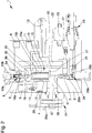
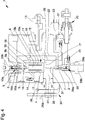
- reference number 1 globally designates a valve assembly connectable to a trailer comprising a first and a second female joint (not shown in the figures) in turn connectable to a first and to a second male joint (also not shown in the figures) respectively, associated with the towing vehicle.
- first female joint is communicating with a control line, able to receive a work fluid at a first pressure as a result of the connection to the first male joint for the power supply of the braking system of the trailer
- second female joint is communicating with at least an additional line, able to receive a work fluid at a second pressure as a result of the connection of the second female joint to the second male joint to control the parking and/or automatic brake of the trailer itself, and to at least a bypass line communicating with a discharge line.
- Valve means are also provided able to put the additional line in communication with the bypass line as a result of the exit of the second male joint from the second female joint.
- the assembly 1 comprises a body 2 inside which are defined: at least a control channel 5 connectable to the control line of the trailer, at least a braking channel 6 connectable to the braking line of the trailer, and at least a connection channel 16 able to put the control channel 5 in communication with the braking channel 6 and along which are placed first valve means 9 able to permit/prevent the flow of the work fluid along the connection channel itself. More particularly, the first valve means 9 are movable between at least a closed position and at least an open position wherein they prevent and permit, respectively, the flow of the work fluid along the connection channel 16.
- the first valve means 9 comprise at least a first and a second shutter 9a and 9b able to obstruct a first and a second passage channel 16a and 16b respectively, of the work fluid inside the connection channel 16 and intended to be moved in sequence to their respective open positions.
- Both shutters 9a and 9b have a respective closed position, wherein they obstruct their passage channel 16a, 16b, and a respective open position, wherein they allow the flow of the work fluid.
- first shutter 9a is slidably inserted within the second shutter 9b, the latter being hollow and defining the first passage channel 16a, moves towards the open position in contrast to first elastic means 10a and protrudes, in its closed position, from the top of the second shutter itself.
- the second shutter 9b rests, in its closed position, against the body 2, so that the second passage channel 16b is positioned outside of the first passage channel 16a.
- the second shutter 9b moves in contrast to the second elastic means 10b.
- the section of the first passage channel 16a is smaller than that of the second passage channel 16b.
- a supply channel 7 connected to a hydraulic accumulator, between which are interposed second valve means 29 able to put in communication/isolate the supply channel 7 with/from the accumulator.
- the second valve means 29 comprise a shutter 29a movable between a closed configuration and an open configuration, wherein it prevents and allows, respectively, the outflow of the work fluid from the accumulator towards the supply channel 7, and elastic means 29b able to counteract the displacement of the shutter 29a towards the open configuration.
- a connecting channel 22 able to put the supply channel 7 in communication with the braking channel 6, and at least an auxiliary channel 20 able to put the control channel 5 in communication with the accumulator and along which are arranged one-way valve means 21 able to prevent the flow of the work fluid from the accumulator to the control channel itself.
- the body 2 are further defined at least an additional channel 11, connectable to the additional line of the trailer, and at least a discharge channel 12, connectable to the discharge line of the trailer.
- the additional channel 11 is connectable to the additional line of the trailer for the deactivation of the parking and/or automatic brake of the trailer itself and the discharge channel 12 can be connectable to a tank, of the dynamic type or not, or without further connections.
- the discharge channel 12 is intended to be put in communication with the additional channel 11, through the bypass channel of the second female joint, as a result of the exit of the second male joint from the relative second female joint.
- the discharge channel 12 is communicating with the control channel 5 and between them is interposed at least a one-way valve 14, which is able to prevent the flow of the work fluid from the control channel 5 towards the discharge channel 12.
- the valve assembly 1 then comprises at least an activation element 15 housed in a sliding manner inside a seat 4 defined in the body 2 and able to interact with the first and second valve means 9 and 29.
- the activation element 15 is then interposed between the first and second valve means 9, 29 and on it act a first thrust chamber 17, facing to the side of the second valve means 29, and a second thrust chamber 18, arranged on the opposite side of the first thrust chamber 17 with respect to the activation element itself and, consequently, facing to the side of the first valve means 9.
- Elastic means 19 are also provided able to act on the activation element 15 towards the first thrust chamber 17. In other words, the elastic means 19 push the activation element 15 in contrast to the force exerted on the same by the first thrust chamber 17.
- the elastic means 19 are therefore arranged inside the second thrust chamber 18.
- the thrust areas of the activation element 15 on which act the first and the second thrust chamber 17 and 18 are substantially equivalent to each other.
- the first and second thrust chambers 17 and 18 are connectable to at least one of the additional channel 11 and the discharge channel 12.
- the valve assembly 1 also comprises a solenoid valve 13, connectable to the power supply of the towing vehicle, and connected to the additional channel 11, to the discharge channel 12 and to the thrust chambers 17 and 18.
- the solenoid valve 13 is movable between at least an inactive configuration, wherein the first and second thrust chambers 17 and 18 are communicating with each other, and at least an active configuration, wherein the first thrust chamber 17 is connected to the additional channel 11 and the second thrust chamber 18 is connected to the discharge channel 12.
- the second thrust chamber 18 is put in communication with the discharge channel 12 and the solenoid valve 13 is interposed between the first thrust chamber 17, the second thrust chamber 18 and the additional channel 11.
- the solenoid valve 13 puts the first thrust chamber 17 in communication with the additional channel 11 isolating the first thrust chamber 17 from the second thrust chamber 18, while in its inactive configuration the solenoid valve 13 puts the first thrust chamber 17 in communication with the second thrust chamber 18 isolating the first thrust chamber 17 from the additional channel 11.
- first thrust chamber 17 is put in communication with the additional channel 11 and the solenoid valve 13 is interposed among the first thrust chamber 17, the second thrust chamber 18 and the discharge channel 12, and wherein in its inactive configuration the solenoid valve 13 puts the second thrust chamber 18 in communication with the first thrust chamber 17, and therefore with the additional channel 11, isolating the second thrust chamber from the discharge channel 12, and an active configuration, wherein the solenoid valve 13 puts the second thrust chamber 18 in communication with the discharge channel 12, isolating the second thrust chamber from the additional channel 11.
- the solenoid valve 13 is positioned in the inactive configuration as a result of the decoupling of the trailer from the towing vehicle or if the latter does not send any electrical signal to the trailer itself.
- a first interaction element 30, e.g. of the cylinder type is interposed between the activation element 15 and the first valve means 9 between the activation element 15 and the first valve means 9 between the activation element 15 and the first valve means 9 between the activation element 15 and the first valve means 9 positioned at least a first interaction element 30, e.g. of the cylinder type.
- a second interaction element 31 e.g. of the cylinder type.
- the activation element 15 comprises a first thrust element 15a, e.g. of the glass-shaped type and able to cooperate with the second interaction element 31, and a second thrust element 15b, housed inside the first thrust element 15a and able to cooperate with the first interaction element 30.
- the elastic means 19 are interposed between the first and the second thrust elements 15a, 15b.
- the activation element 15 is movable between at least a normal operating position and an emergency position.
- the normal operating position corresponds to the condition wherein the male joints are inserted inside the relative female joints, the solenoid valve 13 is in the active configuration, and wherein the additional channel 11 is pressurized and isolated from the discharge channel 12.
- the activation element 15 moves in contrast to the elastic means 19 due to the pressure in the first thrust chamber 17, the second thrust chamber 18 being connected to the discharge channel 12.
- the second thrust chamber 18 can be released in the control channel 5, by means of the one-way valve 14, in the event of this being at a lower pressure than that in the discharge channel 12, e.g. as a result of the interruption of the braking in the towing vehicle.
- the activation element 15 interacts in sequence with the first and with the second shutter 9a, 9b, through the first interaction element 30, thus opening the first passage channel 16a and, subsequently, the second passage channel 16b.
- the first interaction element 30 is then pushed by the activation element 15 towards the first valve means 9 so as to move in sequence the first and the second shutter 9a, 9b to their respective open positions in contrast to the elastic means 10a, 10b.
- the accumulator is charged when the pressure of the work fluid along the control channel 5 is higher than that found in the accumulator itself.
- An auxiliary channel 20 is communicating on one side with the control channel 5 and on the other side with the accumulator, and along which one-way valve means 21 are arranged able to prevent the flow of the work fluid from the accumulator towards the control channel 5, by means of which one part of the work fluid that flows through the control channel itself is conveyed into the accumulator.
- a pressure switch 23 is also connected to the accumulator.
- the assembly 1 also comprises an electric device (not shown in the figures) operatively connected to the pressure switch, to the solenoid valve 13 and to the power supply of the towing vehicle and able to maintain the solenoid valve 13 in the active configuration until the pressure in the accumulator reaches a predefined value.
- an electric device (not shown in the figures) operatively connected to the pressure switch, to the solenoid valve 13 and to the power supply of the towing vehicle and able to maintain the solenoid valve 13 in the active configuration until the pressure in the accumulator reaches a predefined value.
- the auxiliary channel 20 is directly put in communication with the accumulator.
- the activation element 15 then reaches the emergency position as a result of the drop in pressure in the additional channel 11 (e.g. due to the operation of the parking brake of the towing vehicle) or of the connection of the latter with the discharge channel 12 (e.g. due to the exit of the second male joint from the second female joint) or of the displacement of the solenoid valve 13 to the inactive configuration, the activation element itself is moved by the elastic means 19 towards the second valve means 29 to allow the outflow of the work fluid from the accumulator into the supply channel 7 and from the latter into the braking channel 6 through the connecting channel 22.
- the displacement of the activation element 15 towards the emergency position causes the displacement of the second interaction element 31, which interacts with the shutter 29a of the second valve means 29, moving it to its open position.
- the first valve means 9 are in the closed position, isolating the control channel 5 from the braking channel 6.
- the work fluid contained in the accumulator then flows out through the supply channel 7 and supplies the braking system of the trailer by means of the braking channel 6.
- the first thrust chamber 17 is put in communication with the additional channel 11 and is isolated from the discharge channel 12, consequently the activation element 15 is pushed in contrast to the elastic means 19 moving to the normal operating position.
- both the first and the second valve means 9, 29 are in the closed position. More in detail, when the activation element 15 is arranged against one of the first and the second interaction element 30 and 31 it is spaced at the same time from the other of the second and the first interaction element 31 and 30.
- the assembly 1 comprises manual command means 24, which are operable to command the displacement of the activation element 15 to at least a predefined position.
- the command means 24 are able to be operated as a result of the exit of the male joints from the relative female joints.
- the command means 24 are movable between a neutral position, wherein the activation element 15 is free to move between the normal operating position and the emergency position, and at least a first work position, wherein the activation element 15 is pushed in contrast to the elastic means 19, starting from the emergency position it takes on as a result of the connection between the additional channel 11 and the discharge channel 12 following the exit of the male joints from the female joints, and wherein both the first and the second valve means 9 and 29 are in the closed position.
- the assembly 1 comprises pumping means 25 positioned along the auxiliary channel 20 and operable, with the command means 24 in the first work position, to aspirate the work fluid in the control channel 5 and send it inside the accumulator.
- the pumping means 25 are also able to aspirate the work fluid along the additional channel 11 in the event of the latter being put in communication with the discharge channel 12 as a result of the exit of the second male joint from its second female joint; as mentioned above, in fact, the discharge channel 12 is communicating with the control channel 5.
- the pumping means 25 are of the manual type and are interposed between the one-way valve means 21, which comprise at least two one-way valves able to permit the aspiration of the work fluid from the control channel 5 and the sending thereof towards the accumulator but not vice versa.
- the command means 24 are also movable to a second work position, wherein the activation element 15 is pushed further in contrast to the elastic means 19 with respect to the first work position causing the opening of the first valve means 9 and, then, putting the control channel 5 in communication with the braking channel 6.
- the pumping means 25 are also operable to aspirate the work fluid along the braking channel 6, still passing through the control channel 5, and send it inside the accumulator.
- the command means 24 comprise at least an actuation element 26, of the type of a knob, positioned outside of the body 2 and movable in rotation with respect to it, where such knob 26 is connected to a cam element 27 which interacts with the activation element 15.
- the command means 24 also comprise a safety element 26a associated with the actuation element 26 and connectable to the towing vehicle.
- the safety element 26a is displaced so as to move the command means 24 to their neutral position so that the activation element 15 is pushed by the elastic means 19 to the emergency position causing the first valve means 9 to close and the second valve means 29 to open and the consequent braking of the trailer.
- further elastic means 28 are provided associated with the command means 24 and able to exert a torque on them, in contrast to the displacement of the command means themselves from the neutral position towards the aforementioned work positions.
- the further elastic means 28 are the type of a pin spring having a first pin (not visible in detail in the figures) locked together with the body 2 and a second pin (not visible in detail in the figures) locked together with the actuation element 26, the second pin being able to return to the initial position as a result of the rotation of the actuation element itself.
- the valve assembly making the subject of the present invention also allows to release easily the pressure along the various lines of the trailer, i.e. along the control, the additional and the braking lines, so as to allow the subsequent connection of the male joints to the relative female joints.
Landscapes
- Engineering & Computer Science (AREA)
- Transportation (AREA)
- Mechanical Engineering (AREA)
- Physics & Mathematics (AREA)
- Fluid Mechanics (AREA)
- Valves And Accessory Devices For Braking Systems (AREA)
- Forging (AREA)
- Pens And Brushes (AREA)
Claims (15)
- Ventilbaugruppe (1), insbesondere für Anhänger, die ein erstes und ein zweites weibliches Verbindungsstück umfasst, das mit einem ersten und einem zweiten männlichen Verbindungsstück verbindbar ist, das dem Zugfahrzeug zugeordnet ist, wobei das erste weibliche Verbindungsstück mit einer Steuerleitung des Bremssystems des Anhängers selbst verbunden ist und wobei das zweite weibliche Verbindungsstück mit mindestens einer zusätzlichen Leitung verbunden ist, die auf die Feststell- und/oder automatische Bremse des Anhängers wirkt, die Ventilbaugruppe umfassend
mindestens eine Bypassleitung, die mit einer Auslassleitung verbunden ist, und Ventilmittel, die in der Lage sind, die zusätzliche Leitung als Folge des Austritts des zweiten männlichen Verbindungsstücks aus dem zweiten weiblichen Verbindungsstück in Verbindung mit der Bypassleitung zu bringen, dadurch gekennzeichnet, dass sie umfasst:- einen Körper (2), in dem definiert sind:∘ mindestens ein Steuerkanal (5), der mit der Steuerleitung des Anhängers verbindbar ist;∘ mindestens ein Bremskanal (6), der mit dem Bremssystem des Anhängers verbindbar ist;∘ mindestens ein Verbindungskanal (16), der zwischen dem Steuerkanal (5) und dem Bremskanal (6) angeordnet ist und entlang dem erste Ventilmittel (9) angeordnet sind, um den Fluss des Arbeitsfluids entlang des Verbindungskanals selbst zu ermöglichen/verhindern ;∘ mindestens ein Zuführkanal (7), der mit einem Hydrospeicher verbunden ist, wobei zweite Ventilmittel (29) vorgesehen sind, um den Zuführkanal (7) mit dem Speicher in Verbindung zu setzen/zu trennen;∘ mindestens ein Verbindungskanal (22), um den Zuführkanal (7) in Verbindung mit dem Bremskanal (6) zu bringen;∘ mindestens ein Hilfskanal (20), um den Steuerkanal (5) in Verbindung mit dem Speicher zu bringen, und entlang dessen Einwegventilmittel (21) angeordnet sind, um den Fluidstrom von dem Speicher zu dem Steuerkanal selbst zu verhindern;∘ mindestens ein zusätzlicher Kanal (11), der mit der zusätzlichen Leitung des Anhängers verbindbar ist;∘ mindestens ein Auslasskanal (12), der mit der Auslassleitung des Anhängers verbindbar ist;- mindestens ein Aktivierungselement (15), das gleitend in einem in dem Körper (2) definierten Sitz (4) untergebracht ist, zwischen den ersten und zweiten Ventilmitteln (9, 29) angeordnet ist und auf das auf gegenüberliegenden Seiten derselben mindestens eine erste Schubkammer (17), die der Seite der zweiten Ventilmittel (29) zugewandt ist, und eine zweite Schubkammer (18), die der Seite der ersten Ventilmittel (9) zugewandt ist, wirken, wobei auch elastische Mittel (19) vorgesehen sind, die in der Lage sind, auf das Aktivierungselement einzuwirken, um es in Richtung der ersten Schubkammer (17) zu drücken, wobei die ersten und zweiten Schubkammern (17, 18) mit mindestens einem von den zusätzlichen Kanälen (11) und dem Auslasskanal (12) verbindbar sind;- mindestens ein Magnetventil (13), das mit der Energieversorgung des Zugfahrzeugs verbindbar ist und mit dem zusätzlichen Kanal (11), dem Auslasskanal (12) und den ersten und zweiten Schubkammern (17, 18) verbunden ist, wobei das Magnetventil (13) beweglich ist zwischen mindestens einer inaktiven Konfiguration, wobei die ersten und zweiten Schubkammern (17, 18) miteinander verbunden sind, und mindestens einer aktiven Konfiguration, wobei die erste Schubkammer (17) mit dem zusätzlichen Kanal (11) verbunden ist und die zweite Schubkammer (18) mit dem Auslasskanal (12) verbunden ist;- wobei das Aktivierungselement (15) beweglich ist zwischen mindestens:∘ einer normalen Betriebsposition, die dem Betriebszustand entspricht, bei dem der zusätzliche Kanal (11) unter Druck gesetzt wird und das Magnetventil (13) in der aktiven Konfiguration ist, und bei dem sich das Aktivierungselement selbst im Gegensatz zu der durch die elastischen Mittel (19) ausgeübten Kraft bewegt und mit den ersten Ventilmitteln (9) zusammenwirkt, um den Bremskanal (6) mit dem Steuerkanal (5) in Verbindung zu bringen, wobei der letztere den Speicher über den Hilfskanal (20) mit den zweiten Ventilmitteln (29) in der geschlossenen Position versorgt;∘ und einer Notposition, die dem Betriebszustand entspricht, bei dem ein Druckabfall in dem zusätzlichen Kanal (11) oder der Verbindung des letzteren mit dem Auslasskanal (12) als Folge des Austritts des zweiten männlichen Verbindungsstücks aus seinem zweiten weiblichen Verbindungsstück oder der Verschiebung des Magnetventils (13) in die inaktive Position erfolgt, und wobei das Aktivierungselement selbst mit den zweiten Ventilmitteln (29) zusammenwirkt, um den Abfluss des Arbeitsfluids aus dem Speicher in den Zuführkanal (7) und von dort in den Bremskanal (6) durch den Verbindungskanal (22) zu ermöglichen, und wobei die ersten Ventilmittel (9) in der geschlossenen Position sind, das den Steuerkanal (5) vom Bremskanal (6) trennt. - Ventilbaugruppe (1) nach Anspruch 1, dadurch gekennzeichnet, dass sich beim Übergang von der Notposition in die normale Betriebsposition des Aktivierungselements (15) sowohl die ersten als auch die zweiten Ventilmittel (9, 29) in der geschlossenen Position befinden.
- Ventilbaugruppe (1) nach Anspruch 1 oder 2, dadurch gekennzeichnet, dass sie mindestens ein erstes Interaktionselement (30) umfasst, das zwischen dem Aktivierungselement (15) und den ersten Ventilmitteln (9) angeordnet ist, wobei das Aktivierungselement (15) in der Verschiebung in die normale Betriebsposition in der Lage ist, das erste Interaktionselement (30) in Richtung der ersten Ventilmittel (9) zu schieben, um die letzteren in die offene Position zu bewegen.
- Ventilbaugruppe (1) nach einem oder mehreren der vorhergehenden Ansprüche, dadurch gekennzeichnet, dass sie mindestens ein zweites Interaktionselement (31) umfasst, das zwischen dem Aktivierungselement (15) und den zweiten Ventilmitteln (29) angeordnet ist, wobei das Aktivierungselement (15) in der Verschiebung in die Notposition in der Lage ist, das zweite Interaktionselement (31) in Richtung der zweiten Ventilmittel (29) zu drücken, um die letzteren in die offene Position zu bewegen.
- Ventilbaugruppe (1) nach den Ansprüchen 3 und 4, dadurch gekennzeichnet, dass, wenn das Aktivierungselement (15) an einem der ersten und zweiten Interaktionselemente (30, 31) anliegt, es von dem anderen des zweiten und des ersten Interaktionselements (31, 30) beabstandet ist.
- Ventilbaugruppe (1) nach einem oder mehreren der vorhergehenden Ansprüche, dadurch gekennzeichnet, dass die ersten Ventilmittel (9) mindestens einen ersten und einen zweiten Verschluss (9a, 9b) umfassen, die in der Lage sind, jeweils einen ersten und einen zweiten Durchlasskanal (16a, 16b) des Arbeitsfluids entlang des Verbindungskanals (16) zu blockieren, wobei das Aktivierungselement (15) in der Lage ist, den ersten und zweiten Verschluss (9a, 9b) nacheinander in ihre jeweiligen offenen Positionen zu bewegen, während der Verschiebung hiervon in die normale Betriebsposition.
- Ventilbaugruppe (1) nach Anspruch 6, dadurch gekennzeichnet, dass der erste Verschluss (9a) verschiebbar in den zweiten Verschluss (9b) eingesetzt ist, wobei der letztere hohl ist und den ersten Durchlasskanal (16a) definiert, und in seiner geschlossenen Position von der Oberseite des zweiten Verschlusses selbst vorsteht, wobei das erste Interaktionselement (30) in der Lage ist, den ersten und den zweiten Verschluss (9a, 9b) während der Verschiebung des Aktivierungselements (15) in Richtung der normalen Betriebsposition nacheinander zu kontaktieren.
- Ventilbaugruppe (1) nach einem oder mehreren der vorhergehenden Ansprüche 6 und 7, dadurch gekennzeichnet, dass der zweite Verschluss (9b) in seiner geschlossenen Position gegen den Körper (2) anliegt, wobei der zweite Durchlasskanal (16b) außerhalb des ersten Durchlasskanals (16a) angeordnet ist.
- Ventilbaugruppe (1) nach einem oder mehreren der vorhergehenden Ansprüche, dadurch gekennzeichnet, dass das Aktivierungselement (15) ein erstes Schubelement (15a) mit einer Glasform umfasst, das mit dem zweiten Interaktionselement (31) zusammenwirken kann, und ein zweites Schubelement (15b), das in dem ersten Schubelement (15a) untergebracht ist und mit dem ersten Interaktionselement (30) zusammenwirken kann, wobei die elastischen Mittel (19) zwischen dem ersten und dem zweiten Schubelement (15a, 15b) angeordnet ist.
- Ventilbaugruppe (1) nach einem oder mehreren der vorhergehenden Ansprüche, dadurch gekennzeichnet, dass sie manuelle Befehlsmittel (24) umfasst, die bedienbar sind, um die Verschiebung des Aktivierungselements (15) in mindestens eine vordefinierte Position innerhalb des Sitzes (4) zu befehlen.
- Ventilbaugruppe (1) nach Anspruch 10, dadurch gekennzeichnet, dass die Befehlsmittel (24) zwischen einer neutralen Position, in der sich das Aktivierungselement (15) frei zwischen der normalen Betriebsposition und der Notposition bewegen kann, und mindestens einer ersten Arbeitsposition, in der das Aktivierungselement (15) ausgehend von der Notposition im Gegensatz zu den elastischen Mitteln (19) gedrückt wird, und in der sich die ersten und zweiten Ventilmittel (9, 29) in der geschlossenen Position befinden, beweglich sind.
- Ventilbaugruppe (1) nach Anspruch 11, dadurch gekennzeichnet, dass sie Pumpmittel (25) umfasst, die entlang des Hilfskanals (20) angeordnet und mit den Befehlsmitteln (24) in der ersten Arbeitsposition bedienbar sind, um das Arbeitsfluid in den Steuerkanal (5) zu saugen und an den Speicher zu senden; wobei die Pumpmittel (25) auch in der Lage sind, das Arbeitsfluid in den zusätzlichen Kanal (11) zu saugen, falls dieser als Folge des Austritts des zweiten männlichen Verbindungsstücks aus seinem zweiten weiblichen Verbindungsstück mit dem Auslasskanal (12) in Verbindung gebracht wird, wobei der Auslasskanal (12) mit dem Steuerkanal (5) in Verbindung steht.
- Ventilbaugruppe (1) nach einem oder mehreren der Ansprüche 10 bis 12, dadurch gekennzeichnet, dass die Befehlsmittel (24) auch in eine zweite Arbeitsposition beweglich sind, wobei das Aktivierungselement (15) im Gegensatz zu den elastischen Mitteln (19) in Bezug auf die erste Arbeitsposition weitergeschoben wird und die ersten Ventilmittel (9) in der geöffneten Position sind.
- Ventilbaugruppe (1) nach Anspruch 13, dadurch gekennzeichnet, dass die Pumpmittel (25) mit den Befehlsmitteln (24) in der zweiten Arbeitsposition bedienbar sind, um das Arbeitsfluid entlang des Bremskanals (6) mittels des Steuerkanals (5) zu saugen und an den Speicher zu senden.
- Ventilbaugruppe (1) nach einem oder mehreren der vorhergehenden Ansprüche 10 bis 14, dadurch gekennzeichnet, dass die Befehlsmittel (24) mindestens ein Aktivierungselement (26) umfassen, das außerhalb des Körpers (2) angeordnet ist, der mit einem Nockenelement (27) verbunden ist, das mit dem Aktivierungselement (15) zusammenwirkt und bedienbar ist, um die Befehlsmittel selbst aus der neutralen Position in mindestens eine der Arbeitspositionen und umgekehrt zu bewegen.
Applications Claiming Priority (1)
| Application Number | Priority Date | Filing Date | Title |
|---|---|---|---|
| ITMO2015A000087A ITMO20150087A1 (it) | 2015-04-21 | 2015-04-21 | Blocco valvolare |
Publications (2)
| Publication Number | Publication Date |
|---|---|
| EP3085589A1 EP3085589A1 (de) | 2016-10-26 |
| EP3085589B1 true EP3085589B1 (de) | 2019-06-05 |
Family
ID=53539805
Family Applications (1)
| Application Number | Title | Priority Date | Filing Date |
|---|---|---|---|
| EP16166351.3A Active EP3085589B1 (de) | 2015-04-21 | 2016-04-21 | Ventilanordnung |
Country Status (2)
| Country | Link |
|---|---|
| EP (1) | EP3085589B1 (de) |
| IT (1) | ITMO20150087A1 (de) |
Family Cites Families (2)
| Publication number | Priority date | Publication date | Assignee | Title |
|---|---|---|---|---|
| DE2243472C3 (de) * | 1969-10-17 | 1978-09-14 | Girling Ltd., Birmingham, West Midlands (Grossbritannien) | Zugfahrzeug- und Anhängerbremsanlage mit einer Federspeicherbremse als Feststellbremse in beiden Fahrzeugen |
| FR2897580B1 (fr) * | 2006-02-22 | 2008-05-16 | Poclain Hydraulics Ind Soc Par | Dispositif de commande du freinage hydraulique d'une remorque attelee a un tracteur |
-
2015
- 2015-04-21 IT ITMO2015A000087A patent/ITMO20150087A1/it unknown
-
2016
- 2016-04-21 EP EP16166351.3A patent/EP3085589B1/de active Active
Non-Patent Citations (1)
| Title |
|---|
| None * |
Also Published As
| Publication number | Publication date |
|---|---|
| ITMO20150087A1 (it) | 2016-10-21 |
| EP3085589A1 (de) | 2016-10-26 |
Similar Documents
| Publication | Publication Date | Title |
|---|---|---|
| EP3481685B1 (de) | Bremssystem für ein fahrzeug | |
| RU2738507C1 (ru) | Клапанное устройство парковочного тормоза | |
| CN107635837B (zh) | 用于挂车的气动式制动设备 | |
| CN107771141B (zh) | 机动车用驻车制动机构 | |
| EP3085590B1 (de) | Vorrichtung zur steuerung des bremssystems eines anhängerfahrzeugs | |
| EP2952398B1 (de) | Ventilvorrichtung | |
| EP3085589B1 (de) | Ventilanordnung | |
| EP3000631B1 (de) | Verbindungssystem für zugfahrzeug-anhänger | |
| EP3225473B1 (de) | Vorrichtung zur anhängerbremssteuerung | |
| EP3294596B1 (de) | Bremssystem | |
| EP3000672B1 (de) | Anhängerventilanordnung | |
| EP3368385B1 (de) | Bremsvorrichtung für anhänger von landwirtschaftlichen maschinen | |
| EA012540B1 (ru) | Способ для отпускания по меньшей мере одного тормозного механизма с пружинным энергоаккумулятором, приводимого в действие средой, передающей давление, а также устройство и гидравлическая схема для осуществления способа | |
| CN108602503B (zh) | 用于挂车的驻车释放阀 | |
| SU795446A3 (ru) | Пневмоуправл емый клапан дл ТОРМОзНОй СиСТЕМы АВТОМОбил | |
| EP3064408B1 (de) | Anhängerbremssteuergerät | |
| EP3401176A1 (de) | Gerät zum kontrollieren der bremsen eines anhängers | |
| EP2955073B1 (de) | Anordnung zur Verbindung Zugfahrzeug-Anhängerfahrzeug | |
| US20190031167A1 (en) | Brake System for a Motor Vehicle, and Method for Operating the Brake System | |
| EP3611063B1 (de) | Zugfahrzeug-anhänger-verbindungsanordnung | |
| EP3650293A1 (de) | Vorrichtung zur steuerung der bremsung eines anhängers | |
| EP3243715B1 (de) | Hydraulischer verteiler zum bremsen eines geräteanhängers | |
| EP4054907B1 (de) | Gerät zum steuern der bremsung eines anhängers | |
| EP4574596A1 (de) | Vorrichtung zur steuerung der bremsung eines anhängers | |
| US20070296267A1 (en) | Apparatus for braking systems of articulated vehicles |
Legal Events
| Date | Code | Title | Description |
|---|---|---|---|
| PUAI | Public reference made under article 153(3) epc to a published international application that has entered the european phase |
Free format text: ORIGINAL CODE: 0009012 |
|
| AK | Designated contracting states |
Kind code of ref document: A1 Designated state(s): AL AT BE BG CH CY CZ DE DK EE ES FI FR GB GR HR HU IE IS IT LI LT LU LV MC MK MT NL NO PL PT RO RS SE SI SK SM TR |
|
| AX | Request for extension of the european patent |
Extension state: BA ME |
|
| 17P | Request for examination filed |
Effective date: 20170426 |
|
| RBV | Designated contracting states (corrected) |
Designated state(s): AL AT BE BG CH CY CZ DE DK EE ES FI FR GB GR HR HU IE IS IT LI LT LU LV MC MK MT NL NO PL PT RO RS SE SI SK SM TR |
|
| STAA | Information on the status of an ep patent application or granted ep patent |
Free format text: STATUS: REQUEST FOR EXAMINATION WAS MADE |
|
| 111Z | Information provided on other rights and legal means of execution |
Free format text: AL AT BE BG CH CY CZ DE DK EE ES FI FR GB GR HR HU IE IS IT LT LU LV MC MK MT NL NO PL PT RO RS SE SI SK SM TR Effective date: 20180208 |
|
| RAP1 | Party data changed (applicant data changed or rights of an application transferred) |
Owner name: SAFIM S.P.A. |
|
| GRAP | Despatch of communication of intention to grant a patent |
Free format text: ORIGINAL CODE: EPIDOSNIGR1 |
|
| STAA | Information on the status of an ep patent application or granted ep patent |
Free format text: STATUS: GRANT OF PATENT IS INTENDED |
|
| INTG | Intention to grant announced |
Effective date: 20181114 |
|
| GRAS | Grant fee paid |
Free format text: ORIGINAL CODE: EPIDOSNIGR3 |
|
| RIN1 | Information on inventor provided before grant (corrected) |
Inventor name: MAMEI, ENRICO Inventor name: MAMEI, ANDREA Inventor name: MAMEI, ERONNE |
|
| GRAA | (expected) grant |
Free format text: ORIGINAL CODE: 0009210 |
|
| STAA | Information on the status of an ep patent application or granted ep patent |
Free format text: STATUS: THE PATENT HAS BEEN GRANTED |
|
| AK | Designated contracting states |
Kind code of ref document: B1 Designated state(s): AL AT BE BG CH CY CZ DE DK EE ES FI FR GB GR HR HU IE IS IT LI LT LU LV MC MK MT NL NO PL PT RO RS SE SI SK SM TR |
|
| REG | Reference to a national code |
Ref country code: GB Ref legal event code: FG4D |
|
| REG | Reference to a national code |
Ref country code: CH Ref legal event code: EP |
|
| REG | Reference to a national code |
Ref country code: AT Ref legal event code: REF Ref document number: 1139676 Country of ref document: AT Kind code of ref document: T Effective date: 20190615 |
|
| REG | Reference to a national code |
Ref country code: DE Ref legal event code: R096 Ref document number: 602016014704 Country of ref document: DE |
|
| REG | Reference to a national code |
Ref country code: IE Ref legal event code: FG4D |
|
| REG | Reference to a national code |
Ref country code: NL Ref legal event code: MP Effective date: 20190605 |
|
| REG | Reference to a national code |
Ref country code: LT Ref legal event code: MG4D |
|
| PG25 | Lapsed in a contracting state [announced via postgrant information from national office to epo] |
Ref country code: FI Free format text: LAPSE BECAUSE OF FAILURE TO SUBMIT A TRANSLATION OF THE DESCRIPTION OR TO PAY THE FEE WITHIN THE PRESCRIBED TIME-LIMIT Effective date: 20190605 Ref country code: AL Free format text: LAPSE BECAUSE OF FAILURE TO SUBMIT A TRANSLATION OF THE DESCRIPTION OR TO PAY THE FEE WITHIN THE PRESCRIBED TIME-LIMIT Effective date: 20190605 Ref country code: HR Free format text: LAPSE BECAUSE OF FAILURE TO SUBMIT A TRANSLATION OF THE DESCRIPTION OR TO PAY THE FEE WITHIN THE PRESCRIBED TIME-LIMIT Effective date: 20190605 Ref country code: NO Free format text: LAPSE BECAUSE OF FAILURE TO SUBMIT A TRANSLATION OF THE DESCRIPTION OR TO PAY THE FEE WITHIN THE PRESCRIBED TIME-LIMIT Effective date: 20190905 Ref country code: SE Free format text: LAPSE BECAUSE OF FAILURE TO SUBMIT A TRANSLATION OF THE DESCRIPTION OR TO PAY THE FEE WITHIN THE PRESCRIBED TIME-LIMIT Effective date: 20190605 Ref country code: ES Free format text: LAPSE BECAUSE OF FAILURE TO SUBMIT A TRANSLATION OF THE DESCRIPTION OR TO PAY THE FEE WITHIN THE PRESCRIBED TIME-LIMIT Effective date: 20190605 Ref country code: LT Free format text: LAPSE BECAUSE OF FAILURE TO SUBMIT A TRANSLATION OF THE DESCRIPTION OR TO PAY THE FEE WITHIN THE PRESCRIBED TIME-LIMIT Effective date: 20190605 |
|
| PG25 | Lapsed in a contracting state [announced via postgrant information from national office to epo] |
Ref country code: LV Free format text: LAPSE BECAUSE OF FAILURE TO SUBMIT A TRANSLATION OF THE DESCRIPTION OR TO PAY THE FEE WITHIN THE PRESCRIBED TIME-LIMIT Effective date: 20190605 Ref country code: BG Free format text: LAPSE BECAUSE OF FAILURE TO SUBMIT A TRANSLATION OF THE DESCRIPTION OR TO PAY THE FEE WITHIN THE PRESCRIBED TIME-LIMIT Effective date: 20190905 Ref country code: RS Free format text: LAPSE BECAUSE OF FAILURE TO SUBMIT A TRANSLATION OF THE DESCRIPTION OR TO PAY THE FEE WITHIN THE PRESCRIBED TIME-LIMIT Effective date: 20190605 Ref country code: GR Free format text: LAPSE BECAUSE OF FAILURE TO SUBMIT A TRANSLATION OF THE DESCRIPTION OR TO PAY THE FEE WITHIN THE PRESCRIBED TIME-LIMIT Effective date: 20190906 |
|
| REG | Reference to a national code |
Ref country code: AT Ref legal event code: MK05 Ref document number: 1139676 Country of ref document: AT Kind code of ref document: T Effective date: 20190605 |
|
| PG25 | Lapsed in a contracting state [announced via postgrant information from national office to epo] |
Ref country code: CZ Free format text: LAPSE BECAUSE OF FAILURE TO SUBMIT A TRANSLATION OF THE DESCRIPTION OR TO PAY THE FEE WITHIN THE PRESCRIBED TIME-LIMIT Effective date: 20190605 Ref country code: PT Free format text: LAPSE BECAUSE OF FAILURE TO SUBMIT A TRANSLATION OF THE DESCRIPTION OR TO PAY THE FEE WITHIN THE PRESCRIBED TIME-LIMIT Effective date: 20191007 Ref country code: SK Free format text: LAPSE BECAUSE OF FAILURE TO SUBMIT A TRANSLATION OF THE DESCRIPTION OR TO PAY THE FEE WITHIN THE PRESCRIBED TIME-LIMIT Effective date: 20190605 Ref country code: AT Free format text: LAPSE BECAUSE OF FAILURE TO SUBMIT A TRANSLATION OF THE DESCRIPTION OR TO PAY THE FEE WITHIN THE PRESCRIBED TIME-LIMIT Effective date: 20190605 Ref country code: EE Free format text: LAPSE BECAUSE OF FAILURE TO SUBMIT A TRANSLATION OF THE DESCRIPTION OR TO PAY THE FEE WITHIN THE PRESCRIBED TIME-LIMIT Effective date: 20190605 Ref country code: RO Free format text: LAPSE BECAUSE OF FAILURE TO SUBMIT A TRANSLATION OF THE DESCRIPTION OR TO PAY THE FEE WITHIN THE PRESCRIBED TIME-LIMIT Effective date: 20190605 Ref country code: NL Free format text: LAPSE BECAUSE OF FAILURE TO SUBMIT A TRANSLATION OF THE DESCRIPTION OR TO PAY THE FEE WITHIN THE PRESCRIBED TIME-LIMIT Effective date: 20190605 |
|
| PG25 | Lapsed in a contracting state [announced via postgrant information from national office to epo] |
Ref country code: SM Free format text: LAPSE BECAUSE OF FAILURE TO SUBMIT A TRANSLATION OF THE DESCRIPTION OR TO PAY THE FEE WITHIN THE PRESCRIBED TIME-LIMIT Effective date: 20190605 Ref country code: IS Free format text: LAPSE BECAUSE OF FAILURE TO SUBMIT A TRANSLATION OF THE DESCRIPTION OR TO PAY THE FEE WITHIN THE PRESCRIBED TIME-LIMIT Effective date: 20191005 |
|
| REG | Reference to a national code |
Ref country code: DE Ref legal event code: R097 Ref document number: 602016014704 Country of ref document: DE |
|
| PG25 | Lapsed in a contracting state [announced via postgrant information from national office to epo] |
Ref country code: TR Free format text: LAPSE BECAUSE OF FAILURE TO SUBMIT A TRANSLATION OF THE DESCRIPTION OR TO PAY THE FEE WITHIN THE PRESCRIBED TIME-LIMIT Effective date: 20190605 |
|
| PLBE | No opposition filed within time limit |
Free format text: ORIGINAL CODE: 0009261 |
|
| STAA | Information on the status of an ep patent application or granted ep patent |
Free format text: STATUS: NO OPPOSITION FILED WITHIN TIME LIMIT |
|
| PG25 | Lapsed in a contracting state [announced via postgrant information from national office to epo] |
Ref country code: PL Free format text: LAPSE BECAUSE OF FAILURE TO SUBMIT A TRANSLATION OF THE DESCRIPTION OR TO PAY THE FEE WITHIN THE PRESCRIBED TIME-LIMIT Effective date: 20190605 Ref country code: DK Free format text: LAPSE BECAUSE OF FAILURE TO SUBMIT A TRANSLATION OF THE DESCRIPTION OR TO PAY THE FEE WITHIN THE PRESCRIBED TIME-LIMIT Effective date: 20190605 |
|
| 26N | No opposition filed |
Effective date: 20200306 |
|
| PG25 | Lapsed in a contracting state [announced via postgrant information from national office to epo] |
Ref country code: SI Free format text: LAPSE BECAUSE OF FAILURE TO SUBMIT A TRANSLATION OF THE DESCRIPTION OR TO PAY THE FEE WITHIN THE PRESCRIBED TIME-LIMIT Effective date: 20190605 |
|
| PG25 | Lapsed in a contracting state [announced via postgrant information from national office to epo] |
Ref country code: MC Free format text: LAPSE BECAUSE OF FAILURE TO SUBMIT A TRANSLATION OF THE DESCRIPTION OR TO PAY THE FEE WITHIN THE PRESCRIBED TIME-LIMIT Effective date: 20190605 |
|
| REG | Reference to a national code |
Ref country code: CH Ref legal event code: PL |
|
| PG25 | Lapsed in a contracting state [announced via postgrant information from national office to epo] |
Ref country code: FR Free format text: LAPSE BECAUSE OF NON-PAYMENT OF DUE FEES Effective date: 20200430 Ref country code: LI Free format text: LAPSE BECAUSE OF NON-PAYMENT OF DUE FEES Effective date: 20200430 Ref country code: CH Free format text: LAPSE BECAUSE OF NON-PAYMENT OF DUE FEES Effective date: 20200430 Ref country code: LU Free format text: LAPSE BECAUSE OF NON-PAYMENT OF DUE FEES Effective date: 20200421 |
|
| REG | Reference to a national code |
Ref country code: BE Ref legal event code: MM Effective date: 20200430 |
|
| PG25 | Lapsed in a contracting state [announced via postgrant information from national office to epo] |
Ref country code: BE Free format text: LAPSE BECAUSE OF NON-PAYMENT OF DUE FEES Effective date: 20200430 |
|
| GBPC | Gb: european patent ceased through non-payment of renewal fee |
Effective date: 20200421 |
|
| PG25 | Lapsed in a contracting state [announced via postgrant information from national office to epo] |
Ref country code: GB Free format text: LAPSE BECAUSE OF NON-PAYMENT OF DUE FEES Effective date: 20200421 Ref country code: IE Free format text: LAPSE BECAUSE OF NON-PAYMENT OF DUE FEES Effective date: 20200421 |
|
| PG25 | Lapsed in a contracting state [announced via postgrant information from national office to epo] |
Ref country code: MT Free format text: LAPSE BECAUSE OF FAILURE TO SUBMIT A TRANSLATION OF THE DESCRIPTION OR TO PAY THE FEE WITHIN THE PRESCRIBED TIME-LIMIT Effective date: 20190605 Ref country code: CY Free format text: LAPSE BECAUSE OF FAILURE TO SUBMIT A TRANSLATION OF THE DESCRIPTION OR TO PAY THE FEE WITHIN THE PRESCRIBED TIME-LIMIT Effective date: 20190605 |
|
| PG25 | Lapsed in a contracting state [announced via postgrant information from national office to epo] |
Ref country code: MK Free format text: LAPSE BECAUSE OF FAILURE TO SUBMIT A TRANSLATION OF THE DESCRIPTION OR TO PAY THE FEE WITHIN THE PRESCRIBED TIME-LIMIT Effective date: 20190605 |
|
| P01 | Opt-out of the competence of the unified patent court (upc) registered |
Effective date: 20230527 |
|
| PGFP | Annual fee paid to national office [announced via postgrant information from national office to epo] |
Ref country code: DE Payment date: 20250429 Year of fee payment: 10 |
|
| PGFP | Annual fee paid to national office [announced via postgrant information from national office to epo] |
Ref country code: IT Payment date: 20250414 Year of fee payment: 10 |