EP3294968B1 - Supporting system for above-ground flooring - Google Patents
Supporting system for above-ground flooring Download PDFInfo
- Publication number
- EP3294968B1 EP3294968B1 EP16732751.9A EP16732751A EP3294968B1 EP 3294968 B1 EP3294968 B1 EP 3294968B1 EP 16732751 A EP16732751 A EP 16732751A EP 3294968 B1 EP3294968 B1 EP 3294968B1
- Authority
- EP
- European Patent Office
- Prior art keywords
- seat
- arched
- supporting system
- grid
- leg
- Prior art date
- Legal status (The legal status is an assumption and is not a legal conclusion. Google has not performed a legal analysis and makes no representation as to the accuracy of the status listed.)
- Active
Links
Images



Classifications
-
- E—FIXED CONSTRUCTIONS
- E04—BUILDING
- E04F—FINISHING WORK ON BUILDINGS, e.g. STAIRS, FLOORS
- E04F15/00—Flooring
- E04F15/02—Flooring or floor layers composed of a number of similar elements
- E04F15/024—Sectional false floors, e.g. computer floors
- E04F15/02447—Supporting structures
- E04F15/02464—Height adjustable elements for supporting the panels or a panel-supporting framework
- E04F15/0247—Screw jacks
-
- E—FIXED CONSTRUCTIONS
- E04—BUILDING
- E04F—FINISHING WORK ON BUILDINGS, e.g. STAIRS, FLOORS
- E04F15/00—Flooring
- E04F15/02—Flooring or floor layers composed of a number of similar elements
- E04F15/024—Sectional false floors, e.g. computer floors
- E04F15/02405—Floor panels
-
- E—FIXED CONSTRUCTIONS
- E04—BUILDING
- E04F—FINISHING WORK ON BUILDINGS, e.g. STAIRS, FLOORS
- E04F15/00—Flooring
- E04F15/02—Flooring or floor layers composed of a number of similar elements
- E04F15/024—Sectional false floors, e.g. computer floors
- E04F15/02447—Supporting structures
- E04F15/02452—Details of junctions between the supporting structures and the panels or a panel-supporting framework
Definitions
- the present invention refers, in general, to a supporting system for raised floorings. More particularly, the present invention refers to a supporting system that is particularly easy to use.
- the raised floorings are systems of suspended flooring in which the walkable area rests on a structure that is raised off the ground so that an inspectable technical space, for example usable for the passage of cables, is obtained between the ground and the walking surface.
- the known supporting elements utilized for the laying of the raised floorings, usually include columns that rest on the ground and support, directly or indirectly, the elements forming the flooring and the walking surface, for example square or rectangular tiles.
- Said columns support each tile along the relative perimeter since the space covered by the tile must be inspectable.
- the tiles are laid on guides or columns along their perimeter by means of suction cups or other devices.
- the structure of the support bearing the tiles is at first built by positioning all the columns that are adjustable in height independently to obtain a support at the desired level. Then, the guides are positioned and the tiles are supported.
- the laying of the guides is performed starting from a side of the room and proceeding to the opposite side and their arrangement requires an inverse intervention, which complicates the disassembly, or an intervention in different points of the flooring which are not near the side on which the laying has been finished. Indeed, the maintenance of the guides requires that the tiles are lifted starting from where the laying has been completed.
- EP0257237A2 discloses a system showing the features of the preamble of claim 1.
- an aim of the invention is to provide a supporting system for raised floorings in order to overcome the problems of the prior art.
- Another aim of the invention is to provide a supporting system for raised floorings at low costs and easy to use.
- Another aim of the invention is to provide a supporting system for raised floorings which allows flexibility of use and is robust and stable.
- Another aim of the invention is to provide a supporting system for raised floorings which ensures a high safety in case of breakage of one or more tiles in the raised flooring.
- a supporting system for at least one tile to obtain floorings raised with respect to a reference ground comprising a grid having at least three sides defining the perimeter of the grid and a supporting surface on which the tile can rest.
- the supporting system is characterized in that at least one first seat formed within the perimeter of the grid and at least one second seat formed along the perimeter of the grid are comprised in the grid.
- At least one sustaining element is comprised and is adapted to rest on the ground and includes at least one protruding body adapted to be inserted in the at least one first seat or the at least one second seat.
- the first seat may comprise a circular seat and at least one arched seat, said circular seat being communicating laterally with the one or more arched seats.
- the second seat may comprise a single arched seat.
- the sustaining element may comprise a supporting element with a body connected laterally to the protruding body, which may be inserted in the arched seat or the single arched seat.
- the supporting element may comprise four protruding bodies arranged around the body at 90 degrees from each other.
- Four arched seats, arranged at 90 degrees from each other, may be connected laterally to each circular seat so that the supporting element may be inserted in the circular seat and the four protruding bodies may be inserted in the four arched seats.
- the sustaining element may comprise a leg which is threaded externally and a thread may be formed on the inner cylindrical surface of the body so that the leg may be screwed or unscrewed in the body.
- a foot may be comprised which rests on the ground and on which the leg rests, a receiving hole being formed in said foot; said leg may be provided with a pin on the lower part, said pin being adapted to be inserted in the receiving hole.
- the receiving hole may communicate with two opposite lateral openings and two opposite wings may protrude from said pin and are adapted to be received in the two lateral openings. In this way, it is possible to rotate the leg and screw or unscrew the leg in the supporting element by rotating the foot.
- the leg may have a cylindrical structure which is empty internally and is holed on the lower part, and the receiving hole for the foot may be a through hole so as to allow eventual liquids to pass through leg and foot.
- the grid may comprise four sides which are orthogonal to each other and form four corners, an arched recess being formed in correspondence of at least one corner.
- a single arched seat is formed in correspondence of said arched recess.
- the supporting element may support four different grids. It is sufficient to dispose the supporting element at an angle of each of said grids.
- each of the four protruding bodies may be connected to the body through a connecting element lower than the protruding body so that said connecting element supports the edges of the arched seat or the single arched seat.
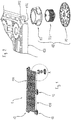
- number 1 denotes a supporting system for raised floorings comprising one or more sustaining elements 10 and a grid 100.
- the sustaining element 10 includes a supporting element 20, a leg 50 and a foot 70, coupled together as described below.
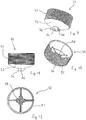
- the supporting element 20 includes a body 21 which is substantially cylindrical, hollow, and internally threaded and which develops in the direction of its central axis.
- a shelf 22 protruding from the lower end of the body 21 develops along the entire circular perimeter of the body 21 since the shelf 22 has a circular shape.
- arched teeth 24 protrude from the shelf 22 vertically and have an upper defined profile 26 and are connected through a respective connecting element 28 to the body 21.
- the four teeth 24 are disposed on the shelf 22 at regular angular intervals of 90 degrees.
- the leg 50 includes a stem 51 which is substantially cylindrical, hollow, and externally threaded and which develops according to its central axis.
- the external thread of the stem 51 is shaped to mate with the internal thread of the body 21 of the supporting element 20.
- a cup 52 and a cylindrical pin 54 protrude from the lower end of the stem 51.
- Two wings 56 protrude from the pin 54.
- a cross-shaped cavity 58 is formed on the internal bottom of the stem 51 and ends with a through hole to allow the eventual passage of fluids or other through the leg 50.
- the foot 70 has a discoid shape and includes a frustum-conical body 71 which forms a single body with a disk 72. Besides, the frustum-conical body 71 and the disk 72 are connected by means of eight ribs 72, only one of them being shown in the figures.
- a cavity 76 is formed inside the frustum-conical body 71.
- a through hole 78 is formed in the center of the cavity and has two openings 80, specular to each other, only one of them being visible in the figure.
- the hole 78 and the openings 80 are shaped so as to receive the pin 54 and the wings 56 of the leg 50.
- the hole 78 may have a diameter greater than the diameter of the pin 54 so as to obtain a coupling with clearance and allow a relative inclination between the leg 50 and the foot 70. Through this coupling with clearance it is thus possible to allow a relative inclination between leg 50 and foot 70 while the sustaining function is ensured by the support of the cup 52 into the cavity 76.
- the openings 80 may have dimensions compatible or smaller than the wings 56 so as to allow the insertion of the wings 56 by an operator who forces the wings in such openings, for example with interference fit, so as to avoid an accidental or unwanted uncoupling of the wings.
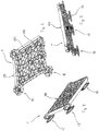
- a grid 100 symmetric to two cross axes, comprises four side edges 104, only one of them being shown in the figure. These four side edges are similar to one another and are connected through a plurality of ribs 102, intersperced with nine circular bodies 106.
- a face of the grid 100 has a flat surface in correspondence of the ribs 102 and circular bodies while the opposite face is more articulated because circular seats 108 are formed in correspondence of the circular bodies 106.
- each circular seat 108 is laterally connected to each circular seat 108.
- the body 21 of a supporting element 20 may be received in each circular seat 108 so that the four arched teeth 24 of the same supporting element 20 are received in the four arched seats 110 corresponding to said circular seat 108, respectively.
- an arched recess 112 is formed in each of the four corners of the grid 100, a single arched seat 114 of the same conformation as the arched seats 110 being obtained in the arched recess 112.
- This configuration allows the coupling of a supporting element 20 also to a corner of the grid 100 by abutting a portion of the relative body 21 on one of the four arched recesses 112 and inserting one of the four teeth in the single arched seat 114 of the arched recess chosen, as shown in Figures 1 and 2 .
- the ribs 102 follow a linear path and are disposed so as to connect the nine circular bodies 106 but it is to be intended that grids comprising a different number of ribs with relative arrangement may be carried out.
- the supporting system for raised floorings provides for the coupling of more grids 100 by utilizing one or more sustaining elements fixed to the corners of one or more grids 100 as visible in Figure 1 .
- each sustaining element 10 consists of a supporting element 20, a leg 50 and a foot 70.
- the stem 51 of the leg 50 is screwed into the body 21 of the supporting element 20 while the wings 56 and the relative pin 54 are received into the openings 80 and hole 78.
- the conformation of the sustaining element 10 allows to adjust the height of the grid 100 by screwing and unscrewing the stem 51 in the body 21.
- the sustaining element 10 may be adapted to any irregularities of conformation of the floor on which the supporting system has be laid since it is possible to incline the foot 70 relative to the leg 50 as described above.
- the conformation of the sustaining element 10 allows to have an assembly flexibility that the sustaining columns or the guides of the prior art do not allow.
- the sustaining element itself may be coupled in a safe, stable way into both the circular seats 108 formed between the ribs of the grids and the arched recesses 112 formed at the corners of the grids without the need of using elements having different shapes.
- the presence of the grid and ribs allows to position tiles or other materials forming the flooring, which have dimensions and/or shapes different from the grid supporting such tiles or other materials while the prior art requires tiles having univocal dimensions determined by the realization of the guides or the positioning of the columns at the corners of the tiles.
- a grid may comprise a number of circular seats different from that described above and represented in the figures.
- arched recesses may be provided not only at the corners of the grid, but also along the side edges.
Landscapes
- Engineering & Computer Science (AREA)
- Architecture (AREA)
- General Engineering & Computer Science (AREA)
- Civil Engineering (AREA)
- Structural Engineering (AREA)
- Floor Finish (AREA)
- Conveying And Assembling Of Building Elements In Situ (AREA)
- Warping, Beaming, Or Leasing (AREA)
- Telephonic Communication Services (AREA)
- Invalid Beds And Related Equipment (AREA)
- Accommodation For Nursing Or Treatment Tables (AREA)
Priority Applications (1)
| Application Number | Priority Date | Filing Date | Title |
|---|---|---|---|
| PL16732751T PL3294968T3 (pl) | 2015-05-12 | 2016-05-11 | Konstrukcja nośna do podłóg podniesionych |
Applications Claiming Priority (2)
| Application Number | Priority Date | Filing Date | Title |
|---|---|---|---|
| ITVR2015A000079A ITVR20150079A1 (it) | 2015-05-12 | 2015-05-12 | Sistema di supporto per pavimentazioni sopraelevate |
| PCT/IB2016/052704 WO2016181328A1 (en) | 2015-05-12 | 2016-05-11 | Supporting system for above-ground flooring |
Publications (2)
| Publication Number | Publication Date |
|---|---|
| EP3294968A1 EP3294968A1 (en) | 2018-03-21 |
| EP3294968B1 true EP3294968B1 (en) | 2019-03-27 |
Family
ID=53794453
Family Applications (1)
| Application Number | Title | Priority Date | Filing Date |
|---|---|---|---|
| EP16732751.9A Active EP3294968B1 (en) | 2015-05-12 | 2016-05-11 | Supporting system for above-ground flooring |
Country Status (10)
| Country | Link |
|---|---|
| US (1) | US10196827B2 (pl) |
| EP (1) | EP3294968B1 (pl) |
| BR (1) | BR112017024307B1 (pl) |
| ES (1) | ES2732680T3 (pl) |
| IT (1) | ITVR20150079A1 (pl) |
| MX (1) | MX375067B (pl) |
| PL (1) | PL3294968T3 (pl) |
| PT (1) | PT3294968T (pl) |
| TR (1) | TR201909488T4 (pl) |
| WO (1) | WO2016181328A1 (pl) |
Cited By (2)
| Publication number | Priority date | Publication date | Assignee | Title |
|---|---|---|---|---|
| DE102022104203A1 (de) | 2022-02-22 | 2023-08-24 | Rainer Burkhardt | Doppelbodensystem |
| EP4696851A1 (de) | 2024-08-15 | 2026-02-18 | Rainer Burkhardt | Doppelbodensystem |
Families Citing this family (13)
| Publication number | Priority date | Publication date | Assignee | Title |
|---|---|---|---|---|
| IT201600107627A1 (it) | 2016-10-25 | 2018-04-25 | Dakota Group S A S Di Zeno Cipriani & C | Sistema di supporto per pavimentazioni sopraelevate e pavimentazione ottenuta con tale sistema di supporto |
| WO2018121892A1 (en) * | 2016-12-27 | 2018-07-05 | Marana Andrea | Support system for raised floors |
| USD868999S1 (en) * | 2017-07-11 | 2019-12-03 | Fxcollaborative Architects Llp | Modular public space structure |
| USD857239S1 (en) * | 2017-07-11 | 2019-08-20 | Fxcollaborative Architects Llp | Modular public space structure |
| USD867621S1 (en) * | 2017-11-30 | 2019-11-19 | Fxcollaborative Architects Llp | Modular public space structure |
| IT201800009593A1 (it) * | 2018-10-19 | 2020-04-19 | Dakota Group Sas Di Zeno Cipriani & C | Spessore livellatore con mezzi flessibili di accoppiamento. |
| US10731350B1 (en) * | 2019-02-18 | 2020-08-04 | Yongzhi Yang | Paver lockdown systems against wind uplift that work with regular pedestals |
| US11168447B2 (en) | 2019-03-19 | 2021-11-09 | Hanover Prest-Paving Company | Paver supporting apparatus |
| US10844613B2 (en) | 2019-03-19 | 2020-11-24 | Hanover Prest-Paving Company | Paver supporting apparatus |
| EP4077834A1 (en) * | 2019-12-17 | 2022-10-26 | Hanover Prest-Paving Company | Paver supporting apparatus |
| IT202000013099A1 (it) * | 2020-06-03 | 2021-12-03 | Geoplast Spa | Sistema di elementi modulari per la realizzazione di pavimentazioni sopraelevate e relativo procedimento |
| CA3201113A1 (en) * | 2020-12-04 | 2022-06-09 | Ramin Tabibnia | Synthetic turf system |
| RU2757724C1 (ru) * | 2021-01-29 | 2021-10-21 | Олег Михайлович Франко | Панель газонной решетки |
Family Cites Families (9)
| Publication number | Priority date | Publication date | Assignee | Title |
|---|---|---|---|---|
| US4736555A (en) * | 1985-05-22 | 1988-04-12 | Sekisui Kagaku Kogyo Kabushiki Kaisha | Free access type floor |
| DE3628772A1 (de) * | 1986-08-25 | 1988-03-03 | Kloeber Fa Hans | Anordnung an doppelboeden |
| JP2707397B2 (ja) * | 1993-04-21 | 1998-01-28 | 住友ゴム工業株式会社 | 床パネル支持脚および二重床 |
| US7454869B2 (en) * | 2006-03-01 | 2008-11-25 | Owen David D | Raised flooring system and method |
| US20080105172A1 (en) * | 2006-11-02 | 2008-05-08 | John Repasky | Pedestal for Ballast Block Decking |
| JP5102598B2 (ja) * | 2007-12-10 | 2012-12-19 | 株式会社ブリヂストン | 床支持具及び床構造 |
| US8011148B2 (en) * | 2008-06-18 | 2011-09-06 | WE Design Partners, LLC | Modular, portable, interlocking decking system |
| US8453391B2 (en) * | 2010-03-26 | 2013-06-04 | Ramin Tabibnia | Apparatus for establishing a paver over a subsurface |
| US9631385B1 (en) * | 2015-06-24 | 2017-04-25 | Brian O. Phillips | Convertible floor panel assembly, composite floor structure, and method for filling an orchestra opening adjacent a theater stage |
-
2015
- 2015-05-12 IT ITVR2015A000079A patent/ITVR20150079A1/it unknown
-
2016
- 2016-05-11 EP EP16732751.9A patent/EP3294968B1/en active Active
- 2016-05-11 TR TR2019/09488T patent/TR201909488T4/tr unknown
- 2016-05-11 US US15/572,854 patent/US10196827B2/en active Active
- 2016-05-11 WO PCT/IB2016/052704 patent/WO2016181328A1/en not_active Ceased
- 2016-05-11 PT PT16732751T patent/PT3294968T/pt unknown
- 2016-05-11 PL PL16732751T patent/PL3294968T3/pl unknown
- 2016-05-11 MX MX2017014109A patent/MX375067B/es active IP Right Grant
- 2016-05-11 BR BR112017024307-5A patent/BR112017024307B1/pt active IP Right Grant
- 2016-05-11 ES ES16732751T patent/ES2732680T3/es active Active
Non-Patent Citations (1)
| Title |
|---|
| None * |
Cited By (2)
| Publication number | Priority date | Publication date | Assignee | Title |
|---|---|---|---|---|
| DE102022104203A1 (de) | 2022-02-22 | 2023-08-24 | Rainer Burkhardt | Doppelbodensystem |
| EP4696851A1 (de) | 2024-08-15 | 2026-02-18 | Rainer Burkhardt | Doppelbodensystem |
Also Published As
| Publication number | Publication date |
|---|---|
| PT3294968T (pt) | 2019-06-11 |
| TR201909488T4 (tr) | 2019-07-22 |
| ES2732680T3 (es) | 2019-11-25 |
| ITVR20150079A1 (it) | 2016-11-12 |
| US10196827B2 (en) | 2019-02-05 |
| WO2016181328A1 (en) | 2016-11-17 |
| BR112017024307B1 (pt) | 2022-08-16 |
| PL3294968T3 (pl) | 2019-09-30 |
| MX2017014109A (es) | 2018-06-19 |
| BR112017024307A2 (pt) | 2018-07-24 |
| MX375067B (es) | 2025-03-06 |
| EP3294968A1 (en) | 2018-03-21 |
| US20180135311A1 (en) | 2018-05-17 |
| CA2985730A1 (en) | 2016-11-17 |
Similar Documents
| Publication | Publication Date | Title |
|---|---|---|
| US10196827B2 (en) | Supporting system for above-ground flooring | |
| EP1304426A2 (en) | Support for raised floors with adjustable height and a swing system | |
| WO2010101089A1 (ja) | プランター支持枠装置 | |
| US20110219687A1 (en) | Post or wall mounted stackable plant pot | |
| KR100772555B1 (ko) | 높낮이 조절 폭이 향상된 건축용 나사형 페데스탈 | |
| KR101243873B1 (ko) | 다양한 형태의 마감재를 지지하는 건축용 페데스탈 | |
| KR101133198B1 (ko) | 경사 조절이 향상된 건축용 페데스탈 | |
| US20190136534A1 (en) | Multifunctional rebar support system for reinforcement of concrete structures | |
| CA2985730C (en) | Supporting system for above-ground flooring | |
| KR101235244B1 (ko) | 높이 조절이 가능한 건축용 블록 | |
| KR101243872B1 (ko) | 뒤틀림 현상을 방지한 건축용 페데스탈 | |
| WO2021024019A1 (en) | Raised floor support with wind resistant coupling head | |
| AU2014203401B2 (en) | Post and Beam Support Block | |
| US12024900B2 (en) | Configurable base for supports for raised floors and support for raised floors comprising said configurable base | |
| KR101055760B1 (ko) | 조정판을 이용한 건축물의 벽체 시공구조 | |
| EP2734686B1 (en) | Supporting element for inclined planes | |
| RU146802U1 (ru) | Регулируемая опорная конструкция, преимущественно для фальшполов | |
| KR20170002145A (ko) | 작물지지대 | |
| EP4239143B1 (en) | Head with reversible adapter for supporting raised floors | |
| KR102936551B1 (ko) | 상하 높이조정이 용이하고, 내진기능을 구비한 물탱크 일체형 건식패드 | |
| KR101470988B1 (ko) | 물탱크 안치 구조체 | |
| EP3192938B1 (en) | Supporting system for raised floors and floor comprising said supporting system | |
| EP4162125A1 (en) | Modular element system for the installation of concrete raised floors and related process | |
| EP2162297A1 (en) | Running gear | |
| RU169484U1 (ru) | Регулируемая опора фальшпола |
Legal Events
| Date | Code | Title | Description |
|---|---|---|---|
| STAA | Information on the status of an ep patent application or granted ep patent |
Free format text: STATUS: THE INTERNATIONAL PUBLICATION HAS BEEN MADE |
|
| PUAI | Public reference made under article 153(3) epc to a published international application that has entered the european phase |
Free format text: ORIGINAL CODE: 0009012 |
|
| STAA | Information on the status of an ep patent application or granted ep patent |
Free format text: STATUS: REQUEST FOR EXAMINATION WAS MADE |
|
| 17P | Request for examination filed |
Effective date: 20171204 |
|
| AK | Designated contracting states |
Kind code of ref document: A1 Designated state(s): AL AT BE BG CH CY CZ DE DK EE ES FI FR GB GR HR HU IE IS IT LI LT LU LV MC MK MT NL NO PL PT RO RS SE SI SK SM TR |
|
| AX | Request for extension of the european patent |
Extension state: BA ME |
|
| DAV | Request for validation of the european patent (deleted) | ||
| DAX | Request for extension of the european patent (deleted) | ||
| GRAP | Despatch of communication of intention to grant a patent |
Free format text: ORIGINAL CODE: EPIDOSNIGR1 |
|
| STAA | Information on the status of an ep patent application or granted ep patent |
Free format text: STATUS: GRANT OF PATENT IS INTENDED |
|
| INTG | Intention to grant announced |
Effective date: 20181016 |
|
| GRAS | Grant fee paid |
Free format text: ORIGINAL CODE: EPIDOSNIGR3 |
|
| GRAA | (expected) grant |
Free format text: ORIGINAL CODE: 0009210 |
|
| STAA | Information on the status of an ep patent application or granted ep patent |
Free format text: STATUS: THE PATENT HAS BEEN GRANTED |
|
| AK | Designated contracting states |
Kind code of ref document: B1 Designated state(s): AL AT BE BG CH CY CZ DE DK EE ES FI FR GB GR HR HU IE IS IT LI LT LU LV MC MK MT NL NO PL PT RO RS SE SI SK SM TR |
|
| REG | Reference to a national code |
Ref country code: GB Ref legal event code: FG4D |
|
| REG | Reference to a national code |
Ref country code: CH Ref legal event code: EP |
|
| REG | Reference to a national code |
Ref country code: AT Ref legal event code: REF Ref document number: 1113262 Country of ref document: AT Kind code of ref document: T Effective date: 20190415 |
|
| REG | Reference to a national code |
Ref country code: IE Ref legal event code: FG4D |
|
| REG | Reference to a national code |
Ref country code: DE Ref legal event code: R096 Ref document number: 602016011630 Country of ref document: DE |
|
| REG | Reference to a national code |
Ref country code: RO Ref legal event code: EPE |
|
| REG | Reference to a national code |
Ref country code: PT Ref legal event code: SC4A Ref document number: 3294968 Country of ref document: PT Date of ref document: 20190611 Kind code of ref document: T Free format text: AVAILABILITY OF NATIONAL TRANSLATION Effective date: 20190529 |
|
| PG25 | Lapsed in a contracting state [announced via postgrant information from national office to epo] |
Ref country code: LT Free format text: LAPSE BECAUSE OF FAILURE TO SUBMIT A TRANSLATION OF THE DESCRIPTION OR TO PAY THE FEE WITHIN THE PRESCRIBED TIME-LIMIT Effective date: 20190327 Ref country code: SE Free format text: LAPSE BECAUSE OF FAILURE TO SUBMIT A TRANSLATION OF THE DESCRIPTION OR TO PAY THE FEE WITHIN THE PRESCRIBED TIME-LIMIT Effective date: 20190327 Ref country code: FI Free format text: LAPSE BECAUSE OF FAILURE TO SUBMIT A TRANSLATION OF THE DESCRIPTION OR TO PAY THE FEE WITHIN THE PRESCRIBED TIME-LIMIT Effective date: 20190327 Ref country code: NO Free format text: LAPSE BECAUSE OF FAILURE TO SUBMIT A TRANSLATION OF THE DESCRIPTION OR TO PAY THE FEE WITHIN THE PRESCRIBED TIME-LIMIT Effective date: 20190627 |
|
| REG | Reference to a national code |
Ref country code: NL Ref legal event code: MP Effective date: 20190327 |
|
| PG25 | Lapsed in a contracting state [announced via postgrant information from national office to epo] |
Ref country code: LV Free format text: LAPSE BECAUSE OF FAILURE TO SUBMIT A TRANSLATION OF THE DESCRIPTION OR TO PAY THE FEE WITHIN THE PRESCRIBED TIME-LIMIT Effective date: 20190327 Ref country code: GR Free format text: LAPSE BECAUSE OF FAILURE TO SUBMIT A TRANSLATION OF THE DESCRIPTION OR TO PAY THE FEE WITHIN THE PRESCRIBED TIME-LIMIT Effective date: 20190628 Ref country code: HR Free format text: LAPSE BECAUSE OF FAILURE TO SUBMIT A TRANSLATION OF THE DESCRIPTION OR TO PAY THE FEE WITHIN THE PRESCRIBED TIME-LIMIT Effective date: 20190327 Ref country code: RS Free format text: LAPSE BECAUSE OF FAILURE TO SUBMIT A TRANSLATION OF THE DESCRIPTION OR TO PAY THE FEE WITHIN THE PRESCRIBED TIME-LIMIT Effective date: 20190327 Ref country code: NL Free format text: LAPSE BECAUSE OF FAILURE TO SUBMIT A TRANSLATION OF THE DESCRIPTION OR TO PAY THE FEE WITHIN THE PRESCRIBED TIME-LIMIT Effective date: 20190327 Ref country code: BG Free format text: LAPSE BECAUSE OF FAILURE TO SUBMIT A TRANSLATION OF THE DESCRIPTION OR TO PAY THE FEE WITHIN THE PRESCRIBED TIME-LIMIT Effective date: 20190627 |
|
| REG | Reference to a national code |
Ref country code: AT Ref legal event code: MK05 Ref document number: 1113262 Country of ref document: AT Kind code of ref document: T Effective date: 20190327 |
|
| REG | Reference to a national code |
Ref country code: SK Ref legal event code: T3 Ref document number: E 31500 Country of ref document: SK |
|
| PG25 | Lapsed in a contracting state [announced via postgrant information from national office to epo] |
Ref country code: EE Free format text: LAPSE BECAUSE OF FAILURE TO SUBMIT A TRANSLATION OF THE DESCRIPTION OR TO PAY THE FEE WITHIN THE PRESCRIBED TIME-LIMIT Effective date: 20190327 Ref country code: AL Free format text: LAPSE BECAUSE OF FAILURE TO SUBMIT A TRANSLATION OF THE DESCRIPTION OR TO PAY THE FEE WITHIN THE PRESCRIBED TIME-LIMIT Effective date: 20190327 |
|
| REG | Reference to a national code |
Ref country code: ES Ref legal event code: FG2A Ref document number: 2732680 Country of ref document: ES Kind code of ref document: T3 Effective date: 20191125 |
|
| PG25 | Lapsed in a contracting state [announced via postgrant information from national office to epo] |
Ref country code: SM Free format text: LAPSE BECAUSE OF FAILURE TO SUBMIT A TRANSLATION OF THE DESCRIPTION OR TO PAY THE FEE WITHIN THE PRESCRIBED TIME-LIMIT Effective date: 20190327 |
|
| REG | Reference to a national code |
Ref country code: CH Ref legal event code: PL |
|
| PG25 | Lapsed in a contracting state [announced via postgrant information from national office to epo] |
Ref country code: IS Free format text: LAPSE BECAUSE OF FAILURE TO SUBMIT A TRANSLATION OF THE DESCRIPTION OR TO PAY THE FEE WITHIN THE PRESCRIBED TIME-LIMIT Effective date: 20190727 Ref country code: AT Free format text: LAPSE BECAUSE OF FAILURE TO SUBMIT A TRANSLATION OF THE DESCRIPTION OR TO PAY THE FEE WITHIN THE PRESCRIBED TIME-LIMIT Effective date: 20190327 |
|
| REG | Reference to a national code |
Ref country code: DE Ref legal event code: R097 Ref document number: 602016011630 Country of ref document: DE |
|
| PG25 | Lapsed in a contracting state [announced via postgrant information from national office to epo] |
Ref country code: MC Free format text: LAPSE BECAUSE OF FAILURE TO SUBMIT A TRANSLATION OF THE DESCRIPTION OR TO PAY THE FEE WITHIN THE PRESCRIBED TIME-LIMIT Effective date: 20190327 Ref country code: CH Free format text: LAPSE BECAUSE OF NON-PAYMENT OF DUE FEES Effective date: 20190531 Ref country code: LI Free format text: LAPSE BECAUSE OF NON-PAYMENT OF DUE FEES Effective date: 20190531 Ref country code: DK Free format text: LAPSE BECAUSE OF FAILURE TO SUBMIT A TRANSLATION OF THE DESCRIPTION OR TO PAY THE FEE WITHIN THE PRESCRIBED TIME-LIMIT Effective date: 20190327 |
|
| REG | Reference to a national code |
Ref country code: BE Ref legal event code: MM Effective date: 20190531 |
|
| PLBE | No opposition filed within time limit |
Free format text: ORIGINAL CODE: 0009261 |
|
| STAA | Information on the status of an ep patent application or granted ep patent |
Free format text: STATUS: NO OPPOSITION FILED WITHIN TIME LIMIT |
|
| PG25 | Lapsed in a contracting state [announced via postgrant information from national office to epo] |
Ref country code: SI Free format text: LAPSE BECAUSE OF FAILURE TO SUBMIT A TRANSLATION OF THE DESCRIPTION OR TO PAY THE FEE WITHIN THE PRESCRIBED TIME-LIMIT Effective date: 20190327 Ref country code: LU Free format text: LAPSE BECAUSE OF NON-PAYMENT OF DUE FEES Effective date: 20190511 |
|
| 26N | No opposition filed |
Effective date: 20200103 |
|
| PG25 | Lapsed in a contracting state [announced via postgrant information from national office to epo] |
Ref country code: IE Free format text: LAPSE BECAUSE OF NON-PAYMENT OF DUE FEES Effective date: 20190511 |
|
| PG25 | Lapsed in a contracting state [announced via postgrant information from national office to epo] |
Ref country code: BE Free format text: LAPSE BECAUSE OF NON-PAYMENT OF DUE FEES Effective date: 20190531 |
|
| PG25 | Lapsed in a contracting state [announced via postgrant information from national office to epo] |
Ref country code: CY Free format text: LAPSE BECAUSE OF FAILURE TO SUBMIT A TRANSLATION OF THE DESCRIPTION OR TO PAY THE FEE WITHIN THE PRESCRIBED TIME-LIMIT Effective date: 20190327 |
|
| PG25 | Lapsed in a contracting state [announced via postgrant information from national office to epo] |
Ref country code: HU Free format text: LAPSE BECAUSE OF FAILURE TO SUBMIT A TRANSLATION OF THE DESCRIPTION OR TO PAY THE FEE WITHIN THE PRESCRIBED TIME-LIMIT; INVALID AB INITIO Effective date: 20160511 Ref country code: MT Free format text: LAPSE BECAUSE OF FAILURE TO SUBMIT A TRANSLATION OF THE DESCRIPTION OR TO PAY THE FEE WITHIN THE PRESCRIBED TIME-LIMIT Effective date: 20190327 |
|
| PG25 | Lapsed in a contracting state [announced via postgrant information from national office to epo] |
Ref country code: MK Free format text: LAPSE BECAUSE OF FAILURE TO SUBMIT A TRANSLATION OF THE DESCRIPTION OR TO PAY THE FEE WITHIN THE PRESCRIBED TIME-LIMIT Effective date: 20190327 |
|
| PGFP | Annual fee paid to national office [announced via postgrant information from national office to epo] |
Ref country code: DE Payment date: 20250528 Year of fee payment: 10 Ref country code: PL Payment date: 20250509 Year of fee payment: 10 |
|
| PGFP | Annual fee paid to national office [announced via postgrant information from national office to epo] |
Ref country code: GB Payment date: 20250528 Year of fee payment: 10 Ref country code: ES Payment date: 20250626 Year of fee payment: 10 |
|
| PGFP | Annual fee paid to national office [announced via postgrant information from national office to epo] |
Ref country code: IT Payment date: 20250521 Year of fee payment: 10 |
|
| PGFP | Annual fee paid to national office [announced via postgrant information from national office to epo] |
Ref country code: PT Payment date: 20250507 Year of fee payment: 10 |
|
| PGFP | Annual fee paid to national office [announced via postgrant information from national office to epo] |
Ref country code: FR Payment date: 20250528 Year of fee payment: 10 |
|
| PGFP | Annual fee paid to national office [announced via postgrant information from national office to epo] |
Ref country code: RO Payment date: 20250508 Year of fee payment: 10 |
|
| PGFP | Annual fee paid to national office [announced via postgrant information from national office to epo] |
Ref country code: TR Payment date: 20250509 Year of fee payment: 10 Ref country code: SK Payment date: 20250509 Year of fee payment: 10 |
|
| PGFP | Annual fee paid to national office [announced via postgrant information from national office to epo] |
Ref country code: CZ Payment date: 20250509 Year of fee payment: 10 |