EP3295154B1 - Method of determining a chemical composition of a slag portion - Google Patents
Method of determining a chemical composition of a slag portion Download PDFInfo
- Publication number
- EP3295154B1 EP3295154B1 EP15729935.5A EP15729935A EP3295154B1 EP 3295154 B1 EP3295154 B1 EP 3295154B1 EP 15729935 A EP15729935 A EP 15729935A EP 3295154 B1 EP3295154 B1 EP 3295154B1
- Authority
- EP
- European Patent Office
- Prior art keywords
- values
- matrix
- order
- slag portion
- chemical composition
- Prior art date
- Legal status (The legal status is an assumption and is not a legal conclusion. Google has not performed a legal analysis and makes no representation as to the accuracy of the status listed.)
- Active
Links
Images

Classifications
-
- G—PHYSICS
- G01—MEASURING; TESTING
- G01J—MEASUREMENT OF INTENSITY, VELOCITY, SPECTRAL CONTENT, POLARISATION, PHASE OR PULSE CHARACTERISTICS OF INFRARED, VISIBLE OR ULTRAVIOLET LIGHT; COLORIMETRY; RADIATION PYROMETRY
- G01J3/00—Spectrometry; Spectrophotometry; Monochromators; Measuring colours
- G01J3/12—Generating the spectrum; Monochromators
- G01J3/14—Generating the spectrum; Monochromators using refracting elements, e.g. prisms
-
- G—PHYSICS
- G01—MEASURING; TESTING
- G01J—MEASUREMENT OF INTENSITY, VELOCITY, SPECTRAL CONTENT, POLARISATION, PHASE OR PULSE CHARACTERISTICS OF INFRARED, VISIBLE OR ULTRAVIOLET LIGHT; COLORIMETRY; RADIATION PYROMETRY
- G01J3/00—Spectrometry; Spectrophotometry; Monochromators; Measuring colours
- G01J3/28—Investigating the spectrum
-
- G—PHYSICS
- G01—MEASURING; TESTING
- G01J—MEASUREMENT OF INTENSITY, VELOCITY, SPECTRAL CONTENT, POLARISATION, PHASE OR PULSE CHARACTERISTICS OF INFRARED, VISIBLE OR ULTRAVIOLET LIGHT; COLORIMETRY; RADIATION PYROMETRY
- G01J3/00—Spectrometry; Spectrophotometry; Monochromators; Measuring colours
- G01J3/28—Investigating the spectrum
- G01J3/2803—Investigating the spectrum using photoelectric array detector
-
- G—PHYSICS
- G01—MEASURING; TESTING
- G01J—MEASUREMENT OF INTENSITY, VELOCITY, SPECTRAL CONTENT, POLARISATION, PHASE OR PULSE CHARACTERISTICS OF INFRARED, VISIBLE OR ULTRAVIOLET LIGHT; COLORIMETRY; RADIATION PYROMETRY
- G01J3/00—Spectrometry; Spectrophotometry; Monochromators; Measuring colours
- G01J3/28—Investigating the spectrum
- G01J3/30—Measuring the intensity of spectral lines directly on the spectrum itself
- G01J3/36—Investigating two or more bands of a spectrum by separate detectors
-
- G—PHYSICS
- G01—MEASURING; TESTING
- G01J—MEASUREMENT OF INTENSITY, VELOCITY, SPECTRAL CONTENT, POLARISATION, PHASE OR PULSE CHARACTERISTICS OF INFRARED, VISIBLE OR ULTRAVIOLET LIGHT; COLORIMETRY; RADIATION PYROMETRY
- G01J3/00—Spectrometry; Spectrophotometry; Monochromators; Measuring colours
- G01J3/28—Investigating the spectrum
- G01J3/42—Absorption spectrometry; Double beam spectrometry; Flicker spectrometry; Reflection spectrometry
-
- G—PHYSICS
- G01—MEASURING; TESTING
- G01N—INVESTIGATING OR ANALYSING MATERIALS BY DETERMINING THEIR CHEMICAL OR PHYSICAL PROPERTIES
- G01N21/00—Investigating or analysing materials by the use of optical means, i.e. using sub-millimetre waves, infrared, visible or ultraviolet light
- G01N21/17—Systems in which incident light is modified in accordance with the properties of the material investigated
- G01N21/25—Colour; Spectral properties, i.e. comparison of effect of material on the light at two or more different wavelengths or wavelength bands
- G01N21/31—Investigating relative effect of material at wavelengths characteristic of specific elements or molecules, e.g. atomic absorption spectrometry
-
- G—PHYSICS
- G01—MEASURING; TESTING
- G01N—INVESTIGATING OR ANALYSING MATERIALS BY DETERMINING THEIR CHEMICAL OR PHYSICAL PROPERTIES
- G01N21/00—Investigating or analysing materials by the use of optical means, i.e. using sub-millimetre waves, infrared, visible or ultraviolet light
- G01N21/17—Systems in which incident light is modified in accordance with the properties of the material investigated
- G01N21/25—Colour; Spectral properties, i.e. comparison of effect of material on the light at two or more different wavelengths or wavelength bands
- G01N21/31—Investigating relative effect of material at wavelengths characteristic of specific elements or molecules, e.g. atomic absorption spectrometry
- G01N21/35—Investigating relative effect of material at wavelengths characteristic of specific elements or molecules, e.g. atomic absorption spectrometry using infrared light
- G01N21/3563—Investigating relative effect of material at wavelengths characteristic of specific elements or molecules, e.g. atomic absorption spectrometry using infrared light for analysing solids; Preparation of samples therefor
-
- G—PHYSICS
- G01—MEASURING; TESTING
- G01N—INVESTIGATING OR ANALYSING MATERIALS BY DETERMINING THEIR CHEMICAL OR PHYSICAL PROPERTIES
- G01N21/00—Investigating or analysing materials by the use of optical means, i.e. using sub-millimetre waves, infrared, visible or ultraviolet light
- G01N21/84—Systems specially adapted for particular applications
- G01N21/85—Investigating moving fluids or granular solids
-
- G—PHYSICS
- G01—MEASURING; TESTING
- G01N—INVESTIGATING OR ANALYSING MATERIALS BY DETERMINING THEIR CHEMICAL OR PHYSICAL PROPERTIES
- G01N33/00—Investigating or analysing materials by specific methods not covered by groups G01N1/00 - G01N31/00
- G01N33/20—Metals
- G01N33/205—Metals in liquid state, e.g. molten metals
Definitions
- the present invention relates to a method of determining a chemical composition of a slag portion.
- the invention also relates to an installation for determining said chemical composition, and to a steel manufacturing method.
- the first route comprises the production of pig iron inside a blast furnace and the transformation of this pig iron into crude steel in an oxygen converter or basic oxygen furnace (BOF).
- the second route consists in melting scraps in an electric arc furnace (EAF) to directly produce crude steel. After any of these routes, crude steel is then refined to obtain the required chemical composition of the steel, this refining step being performed in a ladle furnace (LF).
- EAF electric arc furnace
- pig iron coming from blast furnace is poured into an oxygen converter, possibly comprising scraps.
- Oxygen is blown in the converter to allow decarburization of pig iron and its transformation in liquid steel.
- Mineral additives such as lime and dolomite, are also added in the converter.
- the transformation of pig iron consists of fast oxidation reactions induced by the contact between gaseous oxygen and molten metal, in conditions which are very far from the thermodynamic equilibrium with the other present chemical elements, manganese, silicon or phosphorus for example.
- Such produced oxides, together with the added mineral additives contribute to the formation of a liquid slag, which floats on the surface of the metal bath due to its lower density.
- metal scraps are loaded into a furnace and melted.
- the energy required to melt such solid scraps is mainly provided by electric arcs produced between one or several graphite electrodes and the metallic charge.
- the refining reactions are quite similar to those in the oxygen converter. Oxidation of the unwanted elements is obtained by oxidized impurities in the charge, by pure oxygen injected either through lances or through nozzles in the furnace, or by atmospheric oxygen which enters via furnace orifices.
- the oxidized impurities form the slag.
- Crude steel produced by one of the previous routes is then poured into a ladle to adjust the chemical composition of the steel.
- the analytical quality of the liquid metal is adjusted, including compositional trimming, not only of metallic alloying elements, but also the control of metalloids (C, H, N, O, P, S), to different degrees depending on the grade.
- the type and content of oxide inclusions is controlled, by deoxidation (or "killing") of the steel, generally with aluminum for sheet steels, by calcium treatment to modify their composition, and by controlled floatation.
- Different additives, such as lime, dolomite, fluorspar and/or various fluxes are added in the ladle furnace to perform such treatments.
- the produced impurities form a slag floating on the surface of the molten metal.
- additives are added to remove remaining impurities. So the knowledge of slag composition is of primary importance in order to control the quality of the refined steel.
- the degree of deoxidation and desulfuration of steel is also estimated based on the visual evaluation of slag samples and on the chemical composition of the steel.
- the visual appearance of the cooled down slag is still used during the process.
- adding ferro-alloys and other additives to the batch still has a human component due to the expertise and the subjectivity of the workers.
- spectroscopes are used after the process is completed. This requires additional time for the samples to be prepared.
- An aim of the invention is to provide a method of determining a chemical composition of a slag portion that solves or reduces at least some of the above mentioned issues, in particular that improves the productivity of the manufacturing process and remains easy to implement.
- the invention proposes a method according to claim 1.
- the method comprises one or several of the features corresponding to claims 2 to 7.
- the invention also deals with a method according to claim 8.
- the invention also deals with an installation according to claim 9.
- the installation comprises one or several of the features corresponding to claim 10 and of the following features, taken in isolation or any technical feasible combination:
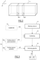
- FIG. 1 With reference to Fig. 1 , there is described an installation 1 performing steps of a method according to the invention.
- the installation 1 is adapted to deal on-line with a slag portion 5.
- the installation 1 comprises a source of light 7, an optical system 10 adapted to collect light L from the slag portion 5, two reference standard elements 12A, 12B located next to the slag portion 5, and optionally a shifting device (not represented) suitable for moving the optical system with respect to the slag portion.
- the slag portion 5 is for example a sample taken from an Electrical Arc Furnace (EAF, not represented) or from a Ladle Furnace (LF, not represented).
- EAF Electrical Arc Furnace
- LF Ladle Furnace
- the slag portion 5 has a chemical composition to be determined.
- the physical aspect of the slag is related to its chemical composition. For example, oxides such as FeO or MnO give a darker aspect to the slag, whereas oxides such as CaO or MgO increase the slag thickness.
- the slag portion 5 has an upper surface S extending along two axes X, Y that are for example substantially perpendicular to each other.
- a third axis Z is also defined as the axis perpendicular to both the axis X and Y.
- the surface S is for example horizontal.
- the chemical composition is for example defined by respective mass fractions of one or several compounds taken from: CaO, SiO2, MgO, Al2O3, S, Fe2O3, FeO, F, MnO,TiO2, Na2O, Cr2O3, Cl, BaO, SrO, P2O5, K2O, ZrO2, ZnO, CuO.
- the source of light 7 is adapted for sending a light beam Li towards the slag portion 5.
- the light source 7 for example includes LED (light emitting diodes) and/or a halogen bulb.
- the two reference standard elements 12A, 12B are for example located on either sides of the slag portion 5 along axis X, advantageously at the same level as the surface S along axis Z.
- the reference standard elements 12A, 12B comprise, for example, stainless steel at a mass fraction of at least 95%, for example AISI 310, with "AISI” meaning "American Iron and Steel Institute”.
- reference standard element 12A As a variant (not represented), a different number of reference standard element(s) is used. For example there is a single one, such as the reference standard element 12A.
- the shifting device is adapted to move the optical system 10 with respect to the surface S for example along axis Y.
- the optical system 10 is suitable for receiving parts L M of the light L from a plurality of points M, of which only one is represented in Fig. 1 .
- the optical system 10 includes at least one CCD or CMOS sensor 25, at least one spectrograph 20, and at least one optical lens 15.
- the plurality of points M are mostly located on the surface S and on the reference standard elements 12A, 12B.
- the points M are advantageously regularly spaced from each other.
- the distance between two M points is, for example, comprised between 0.3 and 1mm,for example 0.5 mm.
- Each point M is for example identified by a first space coordinate x along axis X taken from a first plurality of space coordinate x1, x2, ..., and by a second space coordinate y along axis Y taken from a second plurality of space coordinate y1, y2, ....
- the first plurality of space coordinates x1, x2, ... and the second plurality of space coordinates y1, y2, ... are representative of the plurality of points M.
- the light L is for example light that is reflected by the surface S along axis Z. Surface S is lit by the light source 7. In other embodiments (not represented), the light L is conducted by means of one or multiple optic fiber cables.
- the segment 27 is advantageously substantially parallel to the X axis.
- the segment 27 includes the points M with a same given second space coordinate y , for example y1 as shown in Figure 1 . Due to the optional movement of the optical system 10 along axis Y, the sensor 25 is suitable for scanning successive segments parallel to the segment 27 in order to advantageously cover the whole surface S.
- the spectrograph 20 is for example a Specim V10_04204 imaging spectrograph.
- the spectrograph 20 is able to separate the parts L M of light coming from the point M based on wavelengths represented by a plurality of spectral parameters ⁇ 1, ⁇ 2, ... in order to obtain parts L M, ⁇ 1 , L M, ⁇ 2 , ... which impacts the sensor 25.
- the spectrograph 20 is able to separate the light L coming from the whole segment 27 in order to directly obtain parts L ⁇ 1 , L ⁇ 2 , ... which impact the sensor 25.
- Each part L M, ⁇ is a part of the light L M collected from one of the points M at a given wavelength represented by the spectral parameter ⁇ .
- Each part L ⁇ is a part of the light L collected from the whole segment 27 at a given wavelength represented by the spectral parameter ⁇ .
- Each part L ⁇ contains the parts L M, ⁇ coming from the points M that belong to the segment 27.
- the spectral parameter ⁇ is the wavelength itself in the described example.
- the plurality of spectral parameters ⁇ 1, ⁇ 2, ... is representative of a plurality of wavelengths that are used to determine the chemical composition.
- the plurality of spectral parameters ⁇ 1, ⁇ 2, ... is representative of wavelengths that range between 399 nm and 965 nm.
- the plurality of spectral parameters ⁇ 1, ⁇ 2... is representative of wavelengths that are all comprised between 399 nm and 965 nm.
- the plurality of spectral parameters ⁇ 1, ⁇ 2, ... is regularly spaced and comprises 1024 spectral parameters for example.
- the sensor 25 is adapted for capturing light L.
- the sensor 25 is a CCD or CMOS sensor.
- the sensor 25 is a 2D (two-dimensional) one, for example an IMX174LLJ CMOS sensor.
- the sensor 25 is adapted to receive the parts L M, ⁇ of the light L and to provide values I x,y, ⁇ representative of an intensity of the parts L M, ⁇ .
- the sensor 25 is adapted to generate a block of data B(y1) ( Fig. 2 ) using the parts L ⁇ obtained from the light coming from the segment 27 corresponding to the points M having a second space coordinate equal to y1.
- the sensor 25 is able to generate blocks B(y2), ... corresponding to segments defined by the points M respectively having a second space coordinate equal to y2, .... Altogether the blocks of data B(y) provide the values I x,y, ⁇ .
- the values I x,y, ⁇ form a three-dimensional (3D) matrix ⁇ x,y, ⁇ ( Fig. 2 ), wherein x is one of the first plurality of space coordinates x1, x2, ..., y is one of the second plurality of space coordinates y1, y2, ..., and ⁇ is one of the plurality of spectral parameters ⁇ 1, ⁇ 2, ....Each value I x,y, ⁇ of the matrix ⁇ x,y, ⁇ is for example a gray scale value.
- the matrix is a two-dimensional matrix ⁇ x, ⁇ .
- the matrix ⁇ x,y, ⁇ is usually referred to as a « hyperspectral image » embedding several images ⁇ x,y taken at various wavelengths represented by the spectral parameters ⁇ 1, ⁇ 2, ....
- the installation 1 also comprises at least one computer (not represented) suitable for using the matrix ⁇ x,y, ⁇ in order to determine the chemical composition of the slag portion 5.
- the method 100 aims at determining the chemical composition of the slag portion 5.
- the method 100 is for example intended to be part of a steel production process in which the chemical composition of the slag portion 5 is determined in order to calculate amounts of additives to be added in steel during the process.
- the method 100 comprises a step 110 of providing a data set in the form of a three-dimensional matrix ⁇ x,y, ⁇ , that is to say the hyperspectral image, a step 120 of conditioning the matrix in order to obtain a conditioned matrix, and a step 130 of performing a mathematical algorithm using the conditioned matrix in order to obtain the chemical composition.
- the method 100 further comprises a step 104 of calibration in order to provide values useful for the conditioning step 120, and a training step 106 in order to determine parameters that are used in the conditioning step 120 and the algorithm performance step 130,
- the step 110 of providing the matrix ⁇ x,y, ⁇ includes a substep of providing the slag portion 5, a substep of collecting the light L reflected from the surface S using the optical system 10, and a substep of obtaining a data set from the collected light L, the data set at least defining the matrix ⁇ x,y, ⁇ .
- the data set that is obtained is the matrix ⁇ x,y, ⁇ itself.
- the optical system 10 is moved along axis Y with respect to the surface S in order to scan successive segments of the surface. For each segment, the optical system 10 provides a block of data B(y).
- the blocks of data B(y) altogether form the matrix ⁇ x,y, ⁇ .
- the optical system is not moved with respect to the surface S.
- the step 120 of conditioning includes a substep of segmenting the matrix ⁇ x,y, ⁇ , a substep of normalizing each value I x,y, ⁇ . in the matrix, a substep of spatial smoothing of the values in order to obtain a spectral signature Isig ⁇ , and a substep of size reduction of the spectral signature Isig ⁇ .
- the values I x,y, ⁇ . of the matrix ⁇ x,y, ⁇ are analyzed in order to determine whether the corresponding points M belong to the slag portion 5. Only the values I x,y, ⁇ corresponding to points M belonging to the slag portion 5 are kept in the matrix.
- a derivative of the matrix ⁇ x,y, ⁇ in a single wavelength ⁇ is calculated and values greater than a predetermined threshold are looked for. This allows detecting borders of the slag portion 5 in the hyperspectral image.
- the substep of normalizing provides normalized values Inorm x,y, ⁇ that are free of an influence of an external illumination of the slag portion 5 during the step of collecting the reflected light L. These values Inorm x,y, ⁇ form a matrix Anorm.
- These dark D and white W reference may be obtained in a calibration step 104.
- This calibration step 104 includes a substep of periodic acquisition of a set of dark reference value D and white reference value W.
- the dark reference value D is obtained from an image captured when the optical lens is covered.
- the white reference value W is obtained from a captured image of the reference standard elements 12A, 12B that are in known positions at coordinates X12A and X12B.
- a similar segmentation algorithms than the one described above is used for precise location of the reference standard elements 12A and 12B.
- This calibration step may be performed once at the beginning of the steelmaking campaign or, in a preferred embodiment, it maybe regularly performed to update the reference values.
- the normalization step using this formula allows correcting the hyperspectral image for the impact of the lighting system being not uniform in intensity along different positions x or/and among time or for modifications in the spectral response of the environmental illumination that affect the light received by the sensor 25.
- the substep of spatial smoothing is adapted to provide the spectral signature Isig ⁇ using the normalized values Inorm x,y, ⁇ .
- the spectral signature Isig ⁇ is a more accurate spectral representation of the slag portion 5 as it integrates the noise and acquisition deviations within the sample.
- a spatial smoothing technique is applied to the slag portion 5 within the matrix Anorm. This technique is a computation of a spatial mean at each wavelength over the entire slag portion 5.
- the spectral signature Isig ⁇ may be advantageously completed with additional parameters, for example ratio or subtraction derived from the plurality of spectral parameters ⁇ 1, ⁇ 2... in order to obtain a completed set of values Icomp.
- the plurality of spectral parameters ⁇ 1, ⁇ 2, .... represents 1024 wavelengths.
- the subset of spectral parameters ⁇ ( ⁇ ) to be kept is determined during a sub-step of the training step 106, as described hereunder. It can also be determined through use of abacus, or any adapted method.
- the training step 106 comprises a substep of providing a dataset of Icomp values acquired for a plurality of slag samples of known compositions, and two independent sub-steps 106A and 106B.
- the substep 106A aims at providing the subset of spectral parameters ⁇ ( ⁇ ) to be kept in the size reduction step.
- the substep 106B aims at providing parameters for the algorithm performance step 130, it will be described later.
- the substep 106A uses for example a recursive feature elimination technique where, in order to choose the relevant values, some elements from the completed set of values Icomp are removed.
- a performance parameter of the regression algorithm is for example calculated as the maximum existing correlation between the output of the method according to the invention and the chemical composition of the slag portion 5 that is obtained, for example, from a subset of the training dataset.
- the subset of the training dataset reaching the higher correlation defines the subset of spectral parameters ⁇ ( ⁇ ) to be kept in the size reduction step.
- a subset of values from the completed set of values Icomp is then selected based on the training step 106 and the non-selected values are removed from the signature.
- the values of the selected subset are indexed by the subset of spectral parameters ⁇ ( ⁇ ) selected from the plurality of spectral parameters ⁇ 1, ⁇ 2, ..., said subset of spectral parameters ⁇ ( ⁇ ) being smaller than the plurality of spectral parameters. This allows reducing the size of Icomp in order to obtain a reduced set of values Ired.
- the step 130 of performing a mathematical algorithm comprises a substep of data normalization and a substep of regression.
- the substep of data normalization normalizes the reduced set of values Ired values into a predefined numerical range.
- This substep transforms values measured on different scales to a notionally common scale. It can be based, for example, on subtraction of a minimum value of the dataset and on division by the maximum value of the same dataset.
- the regression step is performed by a regressor which mathematically maps the set of values with an estimated chemical composition values.
- the substep of regression is for example based on a support vector machine model (SVM).
- SVM comprises two different parameters ⁇ (support vectors) and b (offsets) that are determined in the substep 106B of the training step 140.
- Such parameters are known to the skilled person.
- the chemical composition is for example obtained by multiplying the reduced set of values Ired by the vector ⁇ and adding b values. This gives a number that is representative of the chemical composition.
- the training step 106 comprises a substep of providing a dataset of Icomp values acquired for a plurality of slag samples of known compositions, and two independent sub-steps 106A and 106B.
- the substep 106A of providing the subset of spectral parameters ⁇ ( ⁇ ) to be kept in the size reduction step has been previously described.
- the step 106B sets the regressor parameters per each slag compounds for step 130, for example ⁇ and b.
- This substep 106B is based on an off-the-shelf method for SMV training.
- This section includes validation tests that were performed.
- the training dataset composed of LF slag of known composition is divided, for example, into two subsets wherein the first one is used for calculating the regressor parameters and the second one is used for estimating the error and accuracy of the system.
- the error is obtained as the difference between the composition values obtained with a method according to the invention and the actual composition value.
- the composition values are expressed as a percentage.
- the relative standard deviation between compositions obtained with the invention and the XRF known technique range between 5% and 10%. This error assures enough precision in composition during the production process to make a quick assessment of physical state of the slag, so as to define the steel treatment strategy to reach the final process stage at lowest cost.
- the method is fast and does not disrupt the steel production process.
- the method makes it possible to predict the amounts of additives to be added to steel during production in order to obtain a predetermined steel chemical composition.
- the method provides an accurate chemical composition in two to three seconds, whereas prior art methods require sending samples to a laboratory for analysis.
- the slag analyzer system communicates and receives data from the plant, so the evolution of the ladle treatment is known at any time (steel composition, steel and slag weights, additives, temperature). These data together with the information about slag composition extracted allows conducting a global mass balance analysis at any point, so that the thermodynamic equilibrium calculations could be performed using any specific thermodynamic calculation software and the final steel and slag composition could be worked out in equilibrium conditions.
Landscapes
- Physics & Mathematics (AREA)
- Spectroscopy & Molecular Physics (AREA)
- General Physics & Mathematics (AREA)
- Health & Medical Sciences (AREA)
- Life Sciences & Earth Sciences (AREA)
- Chemical & Material Sciences (AREA)
- Immunology (AREA)
- General Health & Medical Sciences (AREA)
- Biochemistry (AREA)
- Pathology (AREA)
- Analytical Chemistry (AREA)
- Engineering & Computer Science (AREA)
- Food Science & Technology (AREA)
- Medicinal Chemistry (AREA)
- Investigating Or Analysing Materials By Optical Means (AREA)
- Treatment Of Steel In Its Molten State (AREA)
- Investigating And Analyzing Materials By Characteristic Methods (AREA)
Applications Claiming Priority (1)
| Application Number | Priority Date | Filing Date | Title |
|---|---|---|---|
| PCT/IB2015/053453 WO2016181185A1 (en) | 2015-05-11 | 2015-05-11 | Method of determining a chemical composition of a slag portion |
Publications (2)
| Publication Number | Publication Date |
|---|---|
| EP3295154A1 EP3295154A1 (en) | 2018-03-21 |
| EP3295154B1 true EP3295154B1 (en) | 2024-10-09 |
Family
ID=53433222
Family Applications (1)
| Application Number | Title | Priority Date | Filing Date |
|---|---|---|---|
| EP15729935.5A Active EP3295154B1 (en) | 2015-05-11 | 2015-05-11 | Method of determining a chemical composition of a slag portion |
Country Status (15)
| Country | Link |
|---|---|
| US (1) | US10677736B2 (pl) |
| EP (1) | EP3295154B1 (pl) |
| JP (1) | JP6905939B2 (pl) |
| KR (1) | KR102093005B1 (pl) |
| CN (1) | CN107787442B (pl) |
| AU (1) | AU2015394657B2 (pl) |
| BR (1) | BR112017024334B1 (pl) |
| CA (1) | CA2985941C (pl) |
| ES (1) | ES2994925T3 (pl) |
| FI (1) | FI3295154T3 (pl) |
| MX (1) | MX386410B (pl) |
| PL (1) | PL3295154T3 (pl) |
| RU (1) | RU2683002C1 (pl) |
| UA (1) | UA120449C2 (pl) |
| WO (1) | WO2016181185A1 (pl) |
Families Citing this family (5)
| Publication number | Priority date | Publication date | Assignee | Title |
|---|---|---|---|---|
| JP6607333B2 (ja) * | 2017-12-15 | 2019-11-20 | Jfeスチール株式会社 | 溶鉄の精錬方法 |
| CN111024228B (zh) * | 2019-12-31 | 2022-08-23 | 杭州高谱成像技术有限公司 | 一种高光谱相机辐射标定装置、方法及系统 |
| US12510485B2 (en) * | 2021-03-10 | 2025-12-30 | Arcelormittal | System and method for determining the chemical composition of liquid metallurgical products |
| JP7111282B1 (ja) * | 2021-05-17 | 2022-08-02 | Jfeスチール株式会社 | スラグの成分分析法、スラグの塩基度分析法および溶融鉄の精錬方法 |
| CN117795323A (zh) * | 2021-07-02 | 2024-03-29 | 诺达技术公司 | 一种用于确定铝生产池中的铝生产熔池的至少一种属性的方法、一种用于确定该至少一种属性的系统、以及一种用于从铝生产池捕获样品的探头 |
Family Cites Families (16)
| Publication number | Priority date | Publication date | Assignee | Title |
|---|---|---|---|---|
| JP3861480B2 (ja) | 1998-11-12 | 2006-12-20 | Jfeスチール株式会社 | スラグの分析方法及び装置 |
| JP2000227396A (ja) * | 1999-02-05 | 2000-08-15 | Kawasaki Steel Corp | スラグ塩基度の決定方法及び装置 |
| CN1795272B (zh) * | 2003-03-27 | 2013-04-24 | 巴特朗医疗成像有限责任公司 | 快速识别病原体、细菌和异常细胞的系统和方法 |
| US6998614B2 (en) | 2003-05-23 | 2006-02-14 | Institute For Technology Development | Hyperspectral imaging workstation having visible/near-infrared and ultraviolet image sensors |
| DE10339595A1 (de) * | 2003-08-26 | 2005-04-07 | Siemens Ag | Verfahren zur Vorhersage und Steuerung der Vergießbarkeit von Flüssigstahl |
| JP2005201636A (ja) | 2004-01-13 | 2005-07-28 | Shizuoka Prefecture | 腐敗部判定方法及び判定装置 |
| DE102004044382A1 (de) | 2004-09-11 | 2006-03-30 | Nowack, Norbert, Prof. Dr.-Ing. | Vorrichtung und Messtechnik zur Erfassung von Schlackenzuständen in der Metallurgie bei hohen Temperaturen durch UV/VIS-Reflektivität |
| US7924414B2 (en) | 2006-05-10 | 2011-04-12 | Abb Schweiz Ag | Non-hazardous bulk material analyzer system |
| EP1862795A1 (en) * | 2006-05-10 | 2007-12-05 | ABB Schweiz AG | Bulk Material Analyzer System |
| WO2008103918A1 (en) * | 2007-02-22 | 2008-08-28 | Wisconsin Alumni Research Foundation | Hyperspectral imaging spectrometer for early detection of skin cancer |
| WO2009142758A1 (en) * | 2008-05-23 | 2009-11-26 | Spectral Image, Inc. | Systems and methods for hyperspectral medical imaging |
| JP5197239B2 (ja) | 2008-08-29 | 2013-05-15 | キヤノン株式会社 | 画像処理装置、画像処理方法及びプログラム |
| JP5715132B2 (ja) * | 2009-08-20 | 2015-05-07 | コーニンクレッカ フィリップス エヌ ヴェ | 画像解析に関する方法及びシステム |
| JP2012098181A (ja) | 2010-11-02 | 2012-05-24 | Sumitomo Electric Ind Ltd | 検出装置及び検出方法 |
| BR112014009061A2 (pt) * | 2011-10-13 | 2017-04-18 | Pioneer Hi Bred Int | método para automaticamente discernir entre pixels de objetos e pixels de não objetos, método para automaticamente discenir entre pixels de planta e pixels de não planta em um cubo hiperespectral de dados de imagem |
| US9237279B2 (en) | 2013-05-06 | 2016-01-12 | Bergen Teknologioverfoering As | Method of investigating a solid sample |
-
2015
- 2015-05-11 KR KR1020177035148A patent/KR102093005B1/ko active Active
- 2015-05-11 CN CN201580081162.5A patent/CN107787442B/zh active Active
- 2015-05-11 JP JP2017559405A patent/JP6905939B2/ja active Active
- 2015-05-11 MX MX2017014474A patent/MX386410B/es unknown
- 2015-05-11 US US15/573,440 patent/US10677736B2/en active Active
- 2015-05-11 FI FIEP15729935.5T patent/FI3295154T3/fi active
- 2015-05-11 CA CA2985941A patent/CA2985941C/en active Active
- 2015-05-11 ES ES15729935T patent/ES2994925T3/es active Active
- 2015-05-11 UA UAA201711993A patent/UA120449C2/uk unknown
- 2015-05-11 EP EP15729935.5A patent/EP3295154B1/en active Active
- 2015-05-11 BR BR112017024334-2A patent/BR112017024334B1/pt active IP Right Grant
- 2015-05-11 PL PL15729935.5T patent/PL3295154T3/pl unknown
- 2015-05-11 AU AU2015394657A patent/AU2015394657B2/en active Active
- 2015-05-11 WO PCT/IB2015/053453 patent/WO2016181185A1/en not_active Ceased
- 2015-05-11 RU RU2017142970A patent/RU2683002C1/ru active
Also Published As
| Publication number | Publication date |
|---|---|
| CN107787442A (zh) | 2018-03-09 |
| MX2017014474A (es) | 2018-04-10 |
| BR112017024334A2 (pt) | 2018-07-24 |
| ES2994925T3 (en) | 2025-02-04 |
| CN107787442B (zh) | 2020-11-03 |
| MX386410B (es) | 2025-03-18 |
| RU2683002C1 (ru) | 2019-03-25 |
| PL3295154T3 (pl) | 2025-02-03 |
| BR112017024334B1 (pt) | 2021-03-02 |
| CA2985941C (en) | 2022-04-26 |
| AU2015394657B2 (en) | 2019-07-11 |
| WO2016181185A1 (en) | 2016-11-17 |
| CA2985941A1 (en) | 2016-11-17 |
| JP2018517903A (ja) | 2018-07-05 |
| EP3295154A1 (en) | 2018-03-21 |
| AU2015394657A1 (en) | 2017-11-30 |
| UA120449C2 (uk) | 2019-12-10 |
| US10677736B2 (en) | 2020-06-09 |
| KR20180004234A (ko) | 2018-01-10 |
| FI3295154T3 (fi) | 2024-11-22 |
| US20180120235A1 (en) | 2018-05-03 |
| JP6905939B2 (ja) | 2021-07-21 |
| KR102093005B1 (ko) | 2020-03-25 |
Similar Documents
| Publication | Publication Date | Title |
|---|---|---|
| US10677736B2 (en) | Method of determining a chemical composition of a slag portion | |
| EP3252457B1 (en) | Metal-body surface state monitoring device and method for monitoring metal-body surface state vorrichtung zur überwachung des oberflächenzustandes von metallkörpern und verfahren zur überwachung des oberflächenzustandes von metallkörpern | |
| CN110989510A (zh) | 一种热镀锌产品全流程质量控制与等级自动判断系统 | |
| CN106670449A (zh) | 一种铁水扒渣测控方法 | |
| Strąkowski et al. | Estimation of FeO content in the steel slag using infrared imaging and artificial neural network | |
| US20220335587A1 (en) | Image inspection apparatus and image inspection method | |
| Picon et al. | Ladle furnace slag characterization through hyperspectral reflectance regression model for secondary metallurgy process optimization | |
| CN111079537B (zh) | 转炉冶炼工况的识别方法、系统、机器可读介质及设备 | |
| Trofimov | Designing an intelligent control system for a basic oxygen furnace based on computer vision | |
| CN117611579B (zh) | 一种钢包内衬在线检测方法及在线检测系统 | |
| RU2710825C2 (ru) | Устройство и способ для управления печью, исходя из измерений образовавшейся окалины | |
| CN120138254A (zh) | 一种转炉炼钢熔池碳含量检测方法、系统、介质及终端 | |
| JP2021166002A (ja) | 焼結鉱の組織構成学習装置、組織構成学習方法及び組織構成学習プログラム | |
| EP1558062B1 (en) | Method for monitoring wear of an electrode | |
| Piva et al. | Calcium-Treated Steel Cleanliness Prediction Using High-Dimensional Steelmaking Process Data | |
| Vicente et al. | Fast method for slag characterization during ladle furnace steelmaking process based on spectral reflectance | |
| KR20100003976A (ko) | 가열로에서 추출된 슬라브의 스케일 등급 판정 시스템 및스케일 저감방법 | |
| JP2022167371A (ja) | ダスト発生速度評価装置及びダスト発生速度評価方法 | |
| Norrena et al. | AMET: platform economy in metals processing | |
| CN121320689A (zh) | 一种基于循环神经网络多渣系算法工艺及应用方法 | |
| CN121504873A (zh) | 一种基于机器视觉的钢包精炼渣化学成分检测方法 | |
| CN121275722A (zh) | 保护渣在线质量检测方法及系统 | |
| CN113740336A (zh) | 一种直接获得连铸坯边部增碳的评价方法 | |
| Toyoda et al. | Prediction of Phosphorus Distribution Ratio between Steel and Slag in Converter using Just-In-Time Modeling and Data-Imputation | |
| da Silva et al. | Digital Transformation in Blast Furnaces: Predictive Model for Intelligent Monitoring of Main Runner Wear |
Legal Events
| Date | Code | Title | Description |
|---|---|---|---|
| STAA | Information on the status of an ep patent application or granted ep patent |
Free format text: STATUS: THE INTERNATIONAL PUBLICATION HAS BEEN MADE |
|
| PUAI | Public reference made under article 153(3) epc to a published international application that has entered the european phase |
Free format text: ORIGINAL CODE: 0009012 |
|
| STAA | Information on the status of an ep patent application or granted ep patent |
Free format text: STATUS: REQUEST FOR EXAMINATION WAS MADE |
|
| 17P | Request for examination filed |
Effective date: 20171110 |
|
| AK | Designated contracting states |
Kind code of ref document: A1 Designated state(s): AL AT BE BG CH CY CZ DE DK EE ES FI FR GB GR HR HU IE IS IT LI LT LU LV MC MK MT NL NO PL PT RO RS SE SI SK SM TR |
|
| AX | Request for extension of the european patent |
Extension state: BA ME |
|
| DAV | Request for validation of the european patent (deleted) | ||
| DAX | Request for extension of the european patent (deleted) | ||
| STAA | Information on the status of an ep patent application or granted ep patent |
Free format text: STATUS: EXAMINATION IS IN PROGRESS |
|
| 17Q | First examination report despatched |
Effective date: 20190604 |
|
| P01 | Opt-out of the competence of the unified patent court (upc) registered |
Effective date: 20230427 |
|
| GRAP | Despatch of communication of intention to grant a patent |
Free format text: ORIGINAL CODE: EPIDOSNIGR1 |
|
| STAA | Information on the status of an ep patent application or granted ep patent |
Free format text: STATUS: GRANT OF PATENT IS INTENDED |
|
| RIC1 | Information provided on ipc code assigned before grant |
Ipc: G01N 33/205 20190101ALI20240506BHEP Ipc: G01J 3/28 20060101ALI20240506BHEP Ipc: G01J 3/14 20060101ALI20240506BHEP Ipc: G01N 21/85 20060101ALI20240506BHEP Ipc: G01N 21/3563 20140101AFI20240506BHEP |
|
| INTG | Intention to grant announced |
Effective date: 20240523 |
|
| GRAS | Grant fee paid |
Free format text: ORIGINAL CODE: EPIDOSNIGR3 |
|
| GRAA | (expected) grant |
Free format text: ORIGINAL CODE: 0009210 |
|
| STAA | Information on the status of an ep patent application or granted ep patent |
Free format text: STATUS: THE PATENT HAS BEEN GRANTED |
|
| AK | Designated contracting states |
Kind code of ref document: B1 Designated state(s): AL AT BE BG CH CY CZ DE DK EE ES FI FR GB GR HR HU IE IS IT LI LT LU LV MC MK MT NL NO PL PT RO RS SE SI SK SM TR |
|
| REG | Reference to a national code |
Ref country code: CH Ref legal event code: EP |
|
| REG | Reference to a national code |
Ref country code: DE Ref legal event code: R096 Ref document number: 602015090080 Country of ref document: DE |
|
| REG | Reference to a national code |
Ref country code: IE Ref legal event code: FG4D |
|
| REG | Reference to a national code |
Ref country code: NL Ref legal event code: FP |
|
| REG | Reference to a national code |
Ref country code: FI Ref legal event code: FGE |
|
| REG | Reference to a national code |
Ref country code: GR Ref legal event code: EP Ref document number: 20240402570 Country of ref document: GR Effective date: 20241209 |
|
| REG | Reference to a national code |
Ref country code: SE Ref legal event code: TRGR |
|
| REG | Reference to a national code |
Ref country code: LT Ref legal event code: MG9D |
|
| REG | Reference to a national code |
Ref country code: ES Ref legal event code: FG2A Ref document number: 2994925 Country of ref document: ES Kind code of ref document: T3 Effective date: 20250204 |
|
| PG25 | Lapsed in a contracting state [announced via postgrant information from national office to epo] |
Ref country code: IS Free format text: LAPSE BECAUSE OF FAILURE TO SUBMIT A TRANSLATION OF THE DESCRIPTION OR TO PAY THE FEE WITHIN THE PRESCRIBED TIME-LIMIT Effective date: 20250209 Ref country code: HR Free format text: LAPSE BECAUSE OF FAILURE TO SUBMIT A TRANSLATION OF THE DESCRIPTION OR TO PAY THE FEE WITHIN THE PRESCRIBED TIME-LIMIT Effective date: 20241009 Ref country code: PT Free format text: LAPSE BECAUSE OF FAILURE TO SUBMIT A TRANSLATION OF THE DESCRIPTION OR TO PAY THE FEE WITHIN THE PRESCRIBED TIME-LIMIT Effective date: 20250210 |
|
| PG25 | Lapsed in a contracting state [announced via postgrant information from national office to epo] |
Ref country code: BG Free format text: LAPSE BECAUSE OF FAILURE TO SUBMIT A TRANSLATION OF THE DESCRIPTION OR TO PAY THE FEE WITHIN THE PRESCRIBED TIME-LIMIT Effective date: 20241009 |
|
| PG25 | Lapsed in a contracting state [announced via postgrant information from national office to epo] |
Ref country code: NO Free format text: LAPSE BECAUSE OF FAILURE TO SUBMIT A TRANSLATION OF THE DESCRIPTION OR TO PAY THE FEE WITHIN THE PRESCRIBED TIME-LIMIT Effective date: 20250109 |
|
| PG25 | Lapsed in a contracting state [announced via postgrant information from national office to epo] |
Ref country code: LV Free format text: LAPSE BECAUSE OF FAILURE TO SUBMIT A TRANSLATION OF THE DESCRIPTION OR TO PAY THE FEE WITHIN THE PRESCRIBED TIME-LIMIT Effective date: 20241009 |
|
| PG25 | Lapsed in a contracting state [announced via postgrant information from national office to epo] |
Ref country code: RS Free format text: LAPSE BECAUSE OF FAILURE TO SUBMIT A TRANSLATION OF THE DESCRIPTION OR TO PAY THE FEE WITHIN THE PRESCRIBED TIME-LIMIT Effective date: 20250109 |
|
| PGFP | Annual fee paid to national office [announced via postgrant information from national office to epo] |
Ref country code: NL Payment date: 20250423 Year of fee payment: 11 |
|
| PGFP | Annual fee paid to national office [announced via postgrant information from national office to epo] |
Ref country code: LU Payment date: 20250423 Year of fee payment: 11 |
|
| PG25 | Lapsed in a contracting state [announced via postgrant information from national office to epo] |
Ref country code: SM Free format text: LAPSE BECAUSE OF FAILURE TO SUBMIT A TRANSLATION OF THE DESCRIPTION OR TO PAY THE FEE WITHIN THE PRESCRIBED TIME-LIMIT Effective date: 20241009 |
|
| PGFP | Annual fee paid to national office [announced via postgrant information from national office to epo] |
Ref country code: FI Payment date: 20250423 Year of fee payment: 11 |
|
| PGFP | Annual fee paid to national office [announced via postgrant information from national office to epo] |
Ref country code: DE Payment date: 20250423 Year of fee payment: 11 Ref country code: PL Payment date: 20250425 Year of fee payment: 11 |
|
| PG25 | Lapsed in a contracting state [announced via postgrant information from national office to epo] |
Ref country code: DK Free format text: LAPSE BECAUSE OF FAILURE TO SUBMIT A TRANSLATION OF THE DESCRIPTION OR TO PAY THE FEE WITHIN THE PRESCRIBED TIME-LIMIT Effective date: 20241009 |
|
| PGFP | Annual fee paid to national office [announced via postgrant information from national office to epo] |
Ref country code: ES Payment date: 20250602 Year of fee payment: 11 |
|
| REG | Reference to a national code |
Ref country code: DE Ref legal event code: R097 Ref document number: 602015090080 Country of ref document: DE |
|
| PGFP | Annual fee paid to national office [announced via postgrant information from national office to epo] |
Ref country code: BE Payment date: 20250423 Year of fee payment: 11 Ref country code: IT Payment date: 20250423 Year of fee payment: 11 |
|
| PG25 | Lapsed in a contracting state [announced via postgrant information from national office to epo] |
Ref country code: EE Free format text: LAPSE BECAUSE OF FAILURE TO SUBMIT A TRANSLATION OF THE DESCRIPTION OR TO PAY THE FEE WITHIN THE PRESCRIBED TIME-LIMIT Effective date: 20241009 |
|
| PGFP | Annual fee paid to national office [announced via postgrant information from national office to epo] |
Ref country code: FR Payment date: 20250423 Year of fee payment: 11 |
|
| PGFP | Annual fee paid to national office [announced via postgrant information from national office to epo] |
Ref country code: GR Payment date: 20250424 Year of fee payment: 11 |
|
| PGFP | Annual fee paid to national office [announced via postgrant information from national office to epo] |
Ref country code: RO Payment date: 20250505 Year of fee payment: 11 Ref country code: AT Payment date: 20250424 Year of fee payment: 11 |
|
| PG25 | Lapsed in a contracting state [announced via postgrant information from national office to epo] |
Ref country code: SK Free format text: LAPSE BECAUSE OF FAILURE TO SUBMIT A TRANSLATION OF THE DESCRIPTION OR TO PAY THE FEE WITHIN THE PRESCRIBED TIME-LIMIT Effective date: 20241009 |
|
| PGFP | Annual fee paid to national office [announced via postgrant information from national office to epo] |
Ref country code: CZ Payment date: 20250429 Year of fee payment: 11 |
|
| PGFP | Annual fee paid to national office [announced via postgrant information from national office to epo] |
Ref country code: SE Payment date: 20250423 Year of fee payment: 11 |
|
| PLBE | No opposition filed within time limit |
Free format text: ORIGINAL CODE: 0009261 |
|
| STAA | Information on the status of an ep patent application or granted ep patent |
Free format text: STATUS: NO OPPOSITION FILED WITHIN TIME LIMIT |
|
| 26N | No opposition filed |
Effective date: 20250710 |
|
| REG | Reference to a national code |
Ref country code: CH Ref legal event code: H13 Free format text: ST27 STATUS EVENT CODE: U-0-0-H10-H13 (AS PROVIDED BY THE NATIONAL OFFICE) Effective date: 20251223 |
|
| REG | Reference to a national code |
Ref country code: AT Ref legal event code: UEP Ref document number: 1731066 Country of ref document: AT Kind code of ref document: T Effective date: 20241009 |
|
| PG25 | Lapsed in a contracting state [announced via postgrant information from national office to epo] |
Ref country code: CH Free format text: LAPSE BECAUSE OF NON-PAYMENT OF DUE FEES Effective date: 20250531 |
|
| PG25 | Lapsed in a contracting state [announced via postgrant information from national office to epo] |
Ref country code: MC Free format text: LAPSE BECAUSE OF FAILURE TO SUBMIT A TRANSLATION OF THE DESCRIPTION OR TO PAY THE FEE WITHIN THE PRESCRIBED TIME-LIMIT Effective date: 20241009 |
|
| PGFP | Annual fee paid to national office [announced via postgrant information from national office to epo] |
Ref country code: GB Payment date: 20260317 Year of fee payment: 12 |
|
| PG25 | Lapsed in a contracting state [announced via postgrant information from national office to epo] |
Ref country code: IE Free format text: LAPSE BECAUSE OF NON-PAYMENT OF DUE FEES Effective date: 20250511 |