EP3295779A1 - Bras supérieur d'attelage pour un bras de relevage à trois points d'un tracteur agricole - Google Patents
Bras supérieur d'attelage pour un bras de relevage à trois points d'un tracteur agricole Download PDFInfo
- Publication number
- EP3295779A1 EP3295779A1 EP17191554.9A EP17191554A EP3295779A1 EP 3295779 A1 EP3295779 A1 EP 3295779A1 EP 17191554 A EP17191554 A EP 17191554A EP 3295779 A1 EP3295779 A1 EP 3295779A1
- Authority
- EP
- European Patent Office
- Prior art keywords
- upper link
- tractor
- universal joint
- sensor module
- insertion opening
- Prior art date
- Legal status (The legal status is an assumption and is not a legal conclusion. Google has not performed a legal analysis and makes no representation as to the accuracy of the status listed.)
- Granted
Links
Images
Classifications
-
- A—HUMAN NECESSITIES
- A01—AGRICULTURE; FORESTRY; ANIMAL HUSBANDRY; HUNTING; TRAPPING; FISHING
- A01B—SOIL WORKING IN AGRICULTURE OR FORESTRY; PARTS, DETAILS, OR ACCESSORIES OF AGRICULTURAL MACHINES OR IMPLEMENTS, IN GENERAL
- A01B59/00—Devices specially adapted for connection between animals or tractors and agricultural machines or implements
- A01B59/002—Details, component parts
- A01B59/006—Latched hooks
-
- A—HUMAN NECESSITIES
- A01—AGRICULTURE; FORESTRY; ANIMAL HUSBANDRY; HUNTING; TRAPPING; FISHING
- A01B—SOIL WORKING IN AGRICULTURE OR FORESTRY; PARTS, DETAILS, OR ACCESSORIES OF AGRICULTURAL MACHINES OR IMPLEMENTS, IN GENERAL
- A01B59/00—Devices specially adapted for connection between animals or tractors and agricultural machines or implements
- A01B59/002—Details, component parts
- A01B59/004—Length-adjustable links
-
- A—HUMAN NECESSITIES
- A01—AGRICULTURE; FORESTRY; ANIMAL HUSBANDRY; HUNTING; TRAPPING; FISHING
- A01B—SOIL WORKING IN AGRICULTURE OR FORESTRY; PARTS, DETAILS, OR ACCESSORIES OF AGRICULTURAL MACHINES OR IMPLEMENTS, IN GENERAL
- A01B59/00—Devices specially adapted for connection between animals or tractors and agricultural machines or implements
- A01B59/06—Devices specially adapted for connection between animals or tractors and agricultural machines or implements for machines mounted on tractors
- A01B59/066—Devices specially adapted for connection between animals or tractors and agricultural machines or implements for machines mounted on tractors of the type comprising at least two lower arms and one upper arm generally arranged in a triangle, e.g. three-point hitches
Definitions
- the invention relates to a length-adjustable upper link for a three-point linkage of an agricultural tractor, with a cylinder body having a cylinder base with a mounting eye on which a universal joint for mounting the tractor side is pivotally mounted.
- Such length-adjustable upper link serve to change the angle of attack of attached to the three-point power lift agricultural implement.
- a rotatable threaded spindle or a hydraulic piston can be guided longitudinally adjustable for the purpose of length adjustment of the upper link.
- the cylinder body is designed as a hydraulic cylinder, which communicates via associated hydraulic lines with a hydraulic control of the agricultural tractor.
- the three-point linkage further includes right and left lower links, which are connected via respective lifting struts with hydraulically pivoting lift arms, so that they can be raised and lowered by operating the hydraulic control of the agricultural tractor.
- the three-point power lift can be provided here in the rear or front area of the agricultural tractor and there serve the attachment of an agricultural attachment or attachment.
- an angle sensor in the form of a potentiometer or incremental rotary encoder is provided for this purpose, which is installed mechanically between a tractor-side attachment point and the universal joint of the upper link.
- a corresponding acceleration sensor is mounted on the outside of the upper link.
- the aforementioned sensors are comparatively sensitive to external damage.
- the top link for a three-point linkage of an agricultural tractor comprises a cylinder body having a cylinder bottom with a mounting eye on which a universal joint for mounting on the tractor side is pivotally mounted. Furthermore, in the universal joint and / or the cylinder bottom an externally accessible insertion opening for receiving a sensor module is formed. A sensor module mounted in it is reliably protected against external damage.
- the sensor module is, in particular, an inertial measuring unit in the form of a so-called MEMS module (MEMS - micro-electro-mechanical system) which contains miniaturized acceleration sensors made of silicon, in particular those for measuring linear accelerations and / or angular velocities or yaw rates (gyroscope sensors). Due to the spatial proximity of the acceleration sensor and to be detected pivotal movement (pivot point) of the top link particularly accurate measurement results can be achieved.
- MEMS module MEMS - micro-electro-mechanical system
- miniaturized acceleration sensors made of silicon, in particular those for measuring linear accelerations and / or angular velocities or yaw rates (gyroscope sensors). Due to the spatial proximity of the acceleration sensor and to be detected pivotal movement (pivot point) of the top link particularly accurate measurement results can be achieved.
- the sensor module typically has the form of an encapsulated module insert, which accommodates the actual measuring system and has on its outside a connector for power supply and for establishing a data connection to a control electronics of the agricultural tractor.
- the transmission can in particular be done digitally via a connectable to the connector CAN data bus.
- a wireless data transmission via short-range radio Bluetooth or the like is possible.
- the module insert is made by injection molding and consists for example of glass fiber reinforced plastic.
- the insertion opening can in principle also be formed elsewhere in the upper link, for example in the region of a catch hook, the hydraulic piston or a universal joint pin, which connects the universal joint pivotally with the attachment eye.
- the cylinder bottom can be reinforced or thickened.
- the insertion opening is in particular pocket-shaped formed within the universal joint and / or cylinder base, so that it is open on only one side to the outside, thus providing a particularly good protection of a sensor module received therein.
- the universal joint forms a aligned with the fastening eye first pivot axis and a perpendicular thereto second pivot axis relative to a pivotable connectable to the universal joint tractor side attachment point, wherein the insertion opening and thus a sensor module therein in the direction of one of the two pivot axes or at a defined angle is oriented
- the sensor module preferably has an arrangement of acceleration sensors, whose respective detection areas coincide with the plane defined by the pivot axes angle planes.
- the acceleration sensors contained in the sensor modules are preassembled ready to install, which simplifies an initial assembly as well as a maintenance-related replacement of the sensor modules.
- the insertion opening may be limited to the outside by a mounting flange, wherein the mounting flange forms a flat surface portion for seat-tight attachment of the sensor module.
- a rubber seal may be located between the sensor module and the mounting flange.
- Universal joint or cylinder bottom are usually produced as a casting, which are planed in the region of the mounting flange.
- the mounting collar may be integral with the injection molded module shelf.
- the upper link according to the invention with an integrated therein, ie in the insertion opening inertial measuring unit can serve in particular for carrying out a method for operating state classification of the upper link on an agricultural tractor.
- the measured data provided by the inertial measuring unit are compared with those of a tractor-proof inertial measuring unit in order, in accordance with the comparison of the linear accelerations contained in the measured data and / or angular velocities with respect to the tractor-side attachment point to determine the current angular position of the upper link in the vertical direction and their temporal change.
- the operating states "transport position", “cultivation process” and "attachment position” can be reliably differentiated.
- the upper link takes in the transport position a solid, almost vertical angular position relative to the agricultural tractor.
- the operator moves the top link, whereby its angular position with respect to the agricultural tractor varies in a characteristic manner in time. If the top link attached to the agricultural attachment or attachment, the top link takes a firm, almost horizontal angular position relative to the agricultural tractor, which clearly differs from the nearly vertical angular position in the transport position.
- An analysis of the current angular position of the upper link as well as the temporal change thus allows a simple way an operating state classification of the upper link.
- the information thus obtained is presented to the operator, for example on a display located in a tractor cab display.
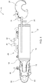
- Fig. 1 shows an embodiment of an upper link according to the invention for a three-point linkage of an agricultural tractor.
- the top link 10 comprises a cylinder body 12 with a cylinder bottom 14, which is an integral part of the cylinder body 12.
- a two-part training is conceivable in which the cylinder base 14 is screwed or compressed pressure-tight with a base 16 of the cylinder body 12.
- the cylinder bottom 14 comprises a fastening eye 18, on which by means of a universal joint pin 20, a universal joint 22 is pivotally mounted.
- a provided at the universal joint 22 receiving opening 24 is used to produce a pivotal connection of the upper link 10 with a (not shown) attachment point of the agricultural tractor.
- the cylinder body 12 is designed as a hydraulic cylinder 26 with a hydraulic piston 28 guided therein.
- the hydraulic piston 28 is connected via associated hydraulic lines 30, 32 with a (not shown) hydraulic control of the agricultural tractor in connection, which makes a length adjustment of the upper link 10 possible.
- a provided in an end portion 34 of the hydraulic piston 28 fishing hooks 36 serves to attach an upper coupling point of an agricultural attachment or accessory, ie a tillage implement, an additional weight, or the like.
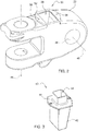
- Fig. 2 shows a perspective view of the covered by the upper link 10 universal joint 22.
- the universal joint 22 is an externally accessible pocket-shaped insertion opening 38 for receiving a in Fig. 3 formed sensor module 40 shown in perspective.
- the sensor module 40 is an inertial measuring unit in the form of a so-called MEMS module (MEMS - micro-electro-mechanical system) which contains miniaturized acceleration sensors made of silicon, in particular those for measuring linear accelerations and / or angular velocities or angular rates (gyroscope sensors).
- MEMS module MEMS - micro-electro-mechanical system
- miniaturized acceleration sensors made of silicon, in particular those for measuring linear accelerations and / or angular velocities or angular rates (gyroscope sensors).
- the sensor module 40 has the shape of an encapsulated module insert 42, which houses the actual measuring system and on its outside a connector 44 for power supply and for establishing a data connection with an electronic control unit of the agricultural tractor.
- the transmission can take place digitally via a CAN data bus connectable to the connector 44.
- a wireless data transmission via short-range radio Bluetooth or the like is possible.
- the module insert 42 is made by injection molding and consists of glass fiber reinforced plastic.
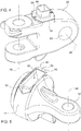
- Fig. 4 shows a perspective view of the universal joint 22 with mounted in the insertion opening 38 sensor module 40th
- the universal joint 22 forms a aligned with the fastening eye 18 first pivot axis 46 and a perpendicular thereto second pivot axis 48 relative to the pivotable with the universal joint 22 tractor-side attachment point, wherein the insertion opening 38 and thus the sensor module 40 therein in the direction of the first pivot axis 46 oriented.
- the respective detection ranges of the acceleration sensors arranged in the sensor module 40 coincide herewith with the angle planes spanned by the pivot axes 46, 48.
- only a vertical pivoting movement of the upper link 10 relative to the tractor-side attachment point should be detected, so that the detection range of the acceleration sensors is reduced in such a case to the plane defined by the second pivot axis 48 angle plane.
- the insertion opening 38 is limited to the outside by a mounting flange 50, wherein the mounting flange 50 forms a flat surface portion 52 for seat-tight attachment of the sensor module 40. Between sensor module 40 and mounting flange 50 is also a rubber seal 54.
- the universal joint 22 is made as a casting, which is planed in the region of the mounting flange 50.
- the mounting collar 60 is an integral part of the module insert 42 made by injection molding.
- the cylinder bottom 14 is designed reinforced or thickened for this purpose, which is apparent from the perspective view Fig. 5 is apparent.
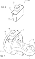
- the sensor module 40 accommodated in the insertion opening 38 is comparable in terms of its construction or function to that of the first embodiment, but has, as in FIG 6 and 7 recognizable, adapted to the installation flatter construction.
Landscapes
- Life Sciences & Earth Sciences (AREA)
- Zoology (AREA)
- Engineering & Computer Science (AREA)
- Mechanical Engineering (AREA)
- Soil Sciences (AREA)
- Environmental Sciences (AREA)
- Lifting Devices For Agricultural Implements (AREA)
- Agricultural Machines (AREA)
Applications Claiming Priority (1)
| Application Number | Priority Date | Filing Date | Title |
|---|---|---|---|
| DE102016217944.6A DE102016217944A1 (de) | 2016-09-20 | 2016-09-20 | Oberlenker für einen Dreipunkt-Kraftheber eines landwirtschaftlichen Traktors |
Publications (2)
| Publication Number | Publication Date |
|---|---|
| EP3295779A1 true EP3295779A1 (fr) | 2018-03-21 |
| EP3295779B1 EP3295779B1 (fr) | 2021-02-24 |
Family
ID=59895220
Family Applications (1)
| Application Number | Title | Priority Date | Filing Date |
|---|---|---|---|
| EP17191554.9A Active EP3295779B1 (fr) | 2016-09-20 | 2017-09-18 | Bras supérieur d'attelage pour un bras de relevage à trois points d'un tracteur agricole |
Country Status (2)
| Country | Link |
|---|---|
| EP (1) | EP3295779B1 (fr) |
| DE (1) | DE102016217944A1 (fr) |
Families Citing this family (2)
| Publication number | Priority date | Publication date | Assignee | Title |
|---|---|---|---|---|
| DE102017210532A1 (de) | 2017-06-22 | 2018-12-27 | Deere & Company | Verfahren zur Bestimmung einer physikalischen Größe eines Oberlenkers |
| DE102018202990A1 (de) | 2018-02-28 | 2019-08-29 | Deere & Company | Verfahren zur Steuerung eines hydraulischen Oberlenkers eines Dreipunkt-Krafthebers |
Citations (8)
| Publication number | Priority date | Publication date | Assignee | Title |
|---|---|---|---|---|
| US4236613A (en) * | 1977-05-09 | 1980-12-02 | Lely Cornelis V D | Coupling member |
| DE2943315A1 (de) * | 1979-10-26 | 1981-05-14 | Erwin Hengstler Hydraulik GmbH, 7613 Hausach | Hydraulisch verstellbarer oberlenker fuer eine dreipunkt-aufhaengung von ackerschleppern |
| US6041582A (en) * | 1998-02-20 | 2000-03-28 | Case Corporation | System for recording soil conditions |
| US6234508B1 (en) * | 1999-09-03 | 2001-05-22 | Case Corporation | Upper link sensing |
| WO2013026661A1 (fr) * | 2011-08-23 | 2013-02-28 | Agco Sa | Système de commande d'attelage côté tracteur agricole |
| EP2769607A1 (fr) * | 2013-02-22 | 2014-08-27 | Cbm - S.P.A. | Stabilisateur latéral pour les machines agricoles |
| DE202015008482U1 (de) * | 2015-12-11 | 2016-02-18 | Alexander Emmrich | Hydraulischer Oberlenker mit integriertem elektonischen Wegmesssystem |
| DE102015201982A1 (de) * | 2015-02-05 | 2016-08-11 | Robert Bosch Gmbh | Verfahren zur Regelung eines Hubwerks einer Arbeitsmaschine |
Family Cites Families (3)
| Publication number | Priority date | Publication date | Assignee | Title |
|---|---|---|---|---|
| US4315548A (en) | 1979-10-01 | 1982-02-16 | Kubota, Ltd. | Tractor with a traction load sensing device |
| DE102010049167A1 (de) | 2010-10-21 | 2012-04-26 | Rauch Landmaschinenfabrik Gmbh | Dreipunkt-Kuppelvorrichtung |
| DE202016003163U1 (de) * | 2016-05-17 | 2016-06-10 | Hans Sauter Gmbh Landtechnik - Stahlbau | Hydraulischer Teleoberlenker mit Druckspeicher |
-
2016
- 2016-09-20 DE DE102016217944.6A patent/DE102016217944A1/de not_active Withdrawn
-
2017
- 2017-09-18 EP EP17191554.9A patent/EP3295779B1/fr active Active
Patent Citations (8)
| Publication number | Priority date | Publication date | Assignee | Title |
|---|---|---|---|---|
| US4236613A (en) * | 1977-05-09 | 1980-12-02 | Lely Cornelis V D | Coupling member |
| DE2943315A1 (de) * | 1979-10-26 | 1981-05-14 | Erwin Hengstler Hydraulik GmbH, 7613 Hausach | Hydraulisch verstellbarer oberlenker fuer eine dreipunkt-aufhaengung von ackerschleppern |
| US6041582A (en) * | 1998-02-20 | 2000-03-28 | Case Corporation | System for recording soil conditions |
| US6234508B1 (en) * | 1999-09-03 | 2001-05-22 | Case Corporation | Upper link sensing |
| WO2013026661A1 (fr) * | 2011-08-23 | 2013-02-28 | Agco Sa | Système de commande d'attelage côté tracteur agricole |
| EP2769607A1 (fr) * | 2013-02-22 | 2014-08-27 | Cbm - S.P.A. | Stabilisateur latéral pour les machines agricoles |
| DE102015201982A1 (de) * | 2015-02-05 | 2016-08-11 | Robert Bosch Gmbh | Verfahren zur Regelung eines Hubwerks einer Arbeitsmaschine |
| DE202015008482U1 (de) * | 2015-12-11 | 2016-02-18 | Alexander Emmrich | Hydraulischer Oberlenker mit integriertem elektonischen Wegmesssystem |
Also Published As
| Publication number | Publication date |
|---|---|
| DE102016217944A1 (de) | 2018-03-22 |
| EP3295779B1 (fr) | 2021-02-24 |
Similar Documents
| Publication | Publication Date | Title |
|---|---|---|
| EP2042276B1 (fr) | Machine agricole et procédé de détermination de position | |
| DE3501568C2 (fr) | ||
| EP2622367B1 (fr) | Porte-capteur pour un capteur de distance | |
| EP3903549B1 (fr) | Machine de traitement du sol, de préférence herse-étrille agricole et procédé de réglage d'une force de précontrainte sur une herse-étrille | |
| EP3494768A1 (fr) | Procédé et dispositif permettant de cartographier un corps étranger existant éventuellement dans un champ | |
| EP4108837A1 (fr) | Système et procédé de localisation d'un outil auxiliaire | |
| DE102012021191B4 (de) | Lader | |
| DE102012021192B4 (de) | Lader | |
| EP0230623A2 (fr) | Véhicule automobile | |
| DE102015102080A1 (de) | Vorrichtung zum Ausbringen von Flüssigkeiten und Verfahren zur Bewegungssteuerung wenigstens zweier Auslegerarme einer landwirtschaftlichen Feldspritze | |
| EP3315926A1 (fr) | Procédé de détermination d'une force pondérale d'une charge utile pour un véhicule utilitaire | |
| DE102018106855A1 (de) | Messeinrichtung zum Messen von Kräften und/oder Momenten zwischen einem motorisierten Fahrzeug und einem davon gezogenen oder geschobenen Anhänger oder Anbaugerät | |
| EP3352141A1 (fr) | Procédé et dispositif d'identification d'un dispositif de montage | |
| DE102019123251A1 (de) | Systeme und verfahren zum kalibrieren eines beschleunigungssensors unter verwendung eines nutzlastsystems | |
| DE102015119073A1 (de) | Regel- oder Steuersystem, landwirtschaftliche Maschine | |
| DE102016117237A1 (de) | Verfahren zum mechanischen Koppeln eines Anbaugerätes mit einem Zugfahrzeug oder einer Anhängevorrichtung | |
| DE102016109425A1 (de) | Messmodul mit Kraft- und Beschleunigungssensoren zur Gewichtsermittlung eines an ein Zugfahrzeug gekoppelten Anhängefahrzeuges | |
| EP3295779B1 (fr) | Bras supérieur d'attelage pour un bras de relevage à trois points d'un tracteur agricole | |
| EP3238515B1 (fr) | Procédé de détermination d'une masse d'équipement porté pour un véhicule utilitaire | |
| EP4133920A2 (fr) | Procédé de mesure d'une hauteur absolue de travail d'une pluralité d'accessoires agricoles | |
| DE60130610T2 (de) | Vorrichtung zum Bearbeiten einer Bodenoberfläche | |
| DE69520556T2 (de) | Vorrichtung zur Detektion der Verschiebung sich bewegender Teile in industriellen Apparaten | |
| EP3311639B1 (fr) | Procédé de calcul de grandeurs géométriques et/ou de réglage caractéristiques d'un relevage à trois points | |
| EP3238516B1 (fr) | Procédé de détermination d'une masse d'équipement porté pour un véhicule utilitaire | |
| EP3143854B1 (fr) | Engin agricole |
Legal Events
| Date | Code | Title | Description |
|---|---|---|---|
| PUAI | Public reference made under article 153(3) epc to a published international application that has entered the european phase |
Free format text: ORIGINAL CODE: 0009012 |
|
| STAA | Information on the status of an ep patent application or granted ep patent |
Free format text: STATUS: THE APPLICATION HAS BEEN PUBLISHED |
|
| AK | Designated contracting states |
Kind code of ref document: A1 Designated state(s): AL AT BE BG CH CY CZ DE DK EE ES FI FR GB GR HR HU IE IS IT LI LT LU LV MC MK MT NL NO PL PT RO RS SE SI SK SM TR |
|
| AX | Request for extension of the european patent |
Extension state: BA ME |
|
| STAA | Information on the status of an ep patent application or granted ep patent |
Free format text: STATUS: REQUEST FOR EXAMINATION WAS MADE |
|
| 17P | Request for examination filed |
Effective date: 20180921 |
|
| RBV | Designated contracting states (corrected) |
Designated state(s): AL AT BE BG CH CY CZ DE DK EE ES FI FR GB GR HR HU IE IS IT LI LT LU LV MC MK MT NL NO PL PT RO RS SE SI SK SM TR |
|
| STAA | Information on the status of an ep patent application or granted ep patent |
Free format text: STATUS: EXAMINATION IS IN PROGRESS |
|
| 17Q | First examination report despatched |
Effective date: 20200129 |
|
| GRAP | Despatch of communication of intention to grant a patent |
Free format text: ORIGINAL CODE: EPIDOSNIGR1 |
|
| STAA | Information on the status of an ep patent application or granted ep patent |
Free format text: STATUS: GRANT OF PATENT IS INTENDED |
|
| RIC1 | Information provided on ipc code assigned before grant |
Ipc: A01B 59/00 20060101AFI20200914BHEP Ipc: A01B 59/06 20060101ALN20200914BHEP |
|
| INTG | Intention to grant announced |
Effective date: 20201001 |
|
| INTG | Intention to grant announced |
Effective date: 20201006 |
|
| INTG | Intention to grant announced |
Effective date: 20201013 |
|
| GRAS | Grant fee paid |
Free format text: ORIGINAL CODE: EPIDOSNIGR3 |
|
| GRAA | (expected) grant |
Free format text: ORIGINAL CODE: 0009210 |
|
| STAA | Information on the status of an ep patent application or granted ep patent |
Free format text: STATUS: THE PATENT HAS BEEN GRANTED |
|
| AK | Designated contracting states |
Kind code of ref document: B1 Designated state(s): AL AT BE BG CH CY CZ DE DK EE ES FI FR GB GR HR HU IE IS IT LI LT LU LV MC MK MT NL NO PL PT RO RS SE SI SK SM TR |
|
| REG | Reference to a national code |
Ref country code: CH Ref legal event code: EP |
|
| REG | Reference to a national code |
Ref country code: AT Ref legal event code: REF Ref document number: 1363282 Country of ref document: AT Kind code of ref document: T Effective date: 20210315 |
|
| REG | Reference to a national code |
Ref country code: IE Ref legal event code: FG4D Free format text: LANGUAGE OF EP DOCUMENT: GERMAN |
|
| REG | Reference to a national code |
Ref country code: DE Ref legal event code: R096 Ref document number: 502017009450 Country of ref document: DE |
|
| REG | Reference to a national code |
Ref country code: LT Ref legal event code: MG9D |
|
| REG | Reference to a national code |
Ref country code: NL Ref legal event code: MP Effective date: 20210224 |
|
| PG25 | Lapsed in a contracting state [announced via postgrant information from national office to epo] |
Ref country code: LT Free format text: LAPSE BECAUSE OF FAILURE TO SUBMIT A TRANSLATION OF THE DESCRIPTION OR TO PAY THE FEE WITHIN THE PRESCRIBED TIME-LIMIT Effective date: 20210224 Ref country code: BG Free format text: LAPSE BECAUSE OF FAILURE TO SUBMIT A TRANSLATION OF THE DESCRIPTION OR TO PAY THE FEE WITHIN THE PRESCRIBED TIME-LIMIT Effective date: 20210524 Ref country code: PT Free format text: LAPSE BECAUSE OF FAILURE TO SUBMIT A TRANSLATION OF THE DESCRIPTION OR TO PAY THE FEE WITHIN THE PRESCRIBED TIME-LIMIT Effective date: 20210624 Ref country code: NO Free format text: LAPSE BECAUSE OF FAILURE TO SUBMIT A TRANSLATION OF THE DESCRIPTION OR TO PAY THE FEE WITHIN THE PRESCRIBED TIME-LIMIT Effective date: 20210524 Ref country code: FI Free format text: LAPSE BECAUSE OF FAILURE TO SUBMIT A TRANSLATION OF THE DESCRIPTION OR TO PAY THE FEE WITHIN THE PRESCRIBED TIME-LIMIT Effective date: 20210224 Ref country code: GR Free format text: LAPSE BECAUSE OF FAILURE TO SUBMIT A TRANSLATION OF THE DESCRIPTION OR TO PAY THE FEE WITHIN THE PRESCRIBED TIME-LIMIT Effective date: 20210525 Ref country code: HR Free format text: LAPSE BECAUSE OF FAILURE TO SUBMIT A TRANSLATION OF THE DESCRIPTION OR TO PAY THE FEE WITHIN THE PRESCRIBED TIME-LIMIT Effective date: 20210224 |
|
| PG25 | Lapsed in a contracting state [announced via postgrant information from national office to epo] |
Ref country code: SE Free format text: LAPSE BECAUSE OF FAILURE TO SUBMIT A TRANSLATION OF THE DESCRIPTION OR TO PAY THE FEE WITHIN THE PRESCRIBED TIME-LIMIT Effective date: 20210224 Ref country code: RS Free format text: LAPSE BECAUSE OF FAILURE TO SUBMIT A TRANSLATION OF THE DESCRIPTION OR TO PAY THE FEE WITHIN THE PRESCRIBED TIME-LIMIT Effective date: 20210224 Ref country code: PL Free format text: LAPSE BECAUSE OF FAILURE TO SUBMIT A TRANSLATION OF THE DESCRIPTION OR TO PAY THE FEE WITHIN THE PRESCRIBED TIME-LIMIT Effective date: 20210224 Ref country code: LV Free format text: LAPSE BECAUSE OF FAILURE TO SUBMIT A TRANSLATION OF THE DESCRIPTION OR TO PAY THE FEE WITHIN THE PRESCRIBED TIME-LIMIT Effective date: 20210224 Ref country code: NL Free format text: LAPSE BECAUSE OF FAILURE TO SUBMIT A TRANSLATION OF THE DESCRIPTION OR TO PAY THE FEE WITHIN THE PRESCRIBED TIME-LIMIT Effective date: 20210224 |
|
| PG25 | Lapsed in a contracting state [announced via postgrant information from national office to epo] |
Ref country code: IS Free format text: LAPSE BECAUSE OF FAILURE TO SUBMIT A TRANSLATION OF THE DESCRIPTION OR TO PAY THE FEE WITHIN THE PRESCRIBED TIME-LIMIT Effective date: 20210624 |
|
| PG25 | Lapsed in a contracting state [announced via postgrant information from national office to epo] |
Ref country code: SM Free format text: LAPSE BECAUSE OF FAILURE TO SUBMIT A TRANSLATION OF THE DESCRIPTION OR TO PAY THE FEE WITHIN THE PRESCRIBED TIME-LIMIT Effective date: 20210224 Ref country code: CZ Free format text: LAPSE BECAUSE OF FAILURE TO SUBMIT A TRANSLATION OF THE DESCRIPTION OR TO PAY THE FEE WITHIN THE PRESCRIBED TIME-LIMIT Effective date: 20210224 Ref country code: EE Free format text: LAPSE BECAUSE OF FAILURE TO SUBMIT A TRANSLATION OF THE DESCRIPTION OR TO PAY THE FEE WITHIN THE PRESCRIBED TIME-LIMIT Effective date: 20210224 |
|
| REG | Reference to a national code |
Ref country code: DE Ref legal event code: R097 Ref document number: 502017009450 Country of ref document: DE |
|
| PG25 | Lapsed in a contracting state [announced via postgrant information from national office to epo] |
Ref country code: DK Free format text: LAPSE BECAUSE OF FAILURE TO SUBMIT A TRANSLATION OF THE DESCRIPTION OR TO PAY THE FEE WITHIN THE PRESCRIBED TIME-LIMIT Effective date: 20210224 Ref country code: RO Free format text: LAPSE BECAUSE OF FAILURE TO SUBMIT A TRANSLATION OF THE DESCRIPTION OR TO PAY THE FEE WITHIN THE PRESCRIBED TIME-LIMIT Effective date: 20210224 Ref country code: SK Free format text: LAPSE BECAUSE OF FAILURE TO SUBMIT A TRANSLATION OF THE DESCRIPTION OR TO PAY THE FEE WITHIN THE PRESCRIBED TIME-LIMIT Effective date: 20210224 |
|
| PLBE | No opposition filed within time limit |
Free format text: ORIGINAL CODE: 0009261 |
|
| STAA | Information on the status of an ep patent application or granted ep patent |
Free format text: STATUS: NO OPPOSITION FILED WITHIN TIME LIMIT |
|
| PG25 | Lapsed in a contracting state [announced via postgrant information from national office to epo] |
Ref country code: AL Free format text: LAPSE BECAUSE OF FAILURE TO SUBMIT A TRANSLATION OF THE DESCRIPTION OR TO PAY THE FEE WITHIN THE PRESCRIBED TIME-LIMIT Effective date: 20210224 Ref country code: ES Free format text: LAPSE BECAUSE OF FAILURE TO SUBMIT A TRANSLATION OF THE DESCRIPTION OR TO PAY THE FEE WITHIN THE PRESCRIBED TIME-LIMIT Effective date: 20210224 |
|
| 26N | No opposition filed |
Effective date: 20211125 |
|
| PG25 | Lapsed in a contracting state [announced via postgrant information from national office to epo] |
Ref country code: SI Free format text: LAPSE BECAUSE OF FAILURE TO SUBMIT A TRANSLATION OF THE DESCRIPTION OR TO PAY THE FEE WITHIN THE PRESCRIBED TIME-LIMIT Effective date: 20210224 |
|
| REG | Reference to a national code |
Ref country code: BE Ref legal event code: MM Effective date: 20210930 |
|
| PG25 | Lapsed in a contracting state [announced via postgrant information from national office to epo] |
Ref country code: IS Free format text: LAPSE BECAUSE OF FAILURE TO SUBMIT A TRANSLATION OF THE DESCRIPTION OR TO PAY THE FEE WITHIN THE PRESCRIBED TIME-LIMIT Effective date: 20210624 Ref country code: MC Free format text: LAPSE BECAUSE OF FAILURE TO SUBMIT A TRANSLATION OF THE DESCRIPTION OR TO PAY THE FEE WITHIN THE PRESCRIBED TIME-LIMIT Effective date: 20210224 |
|
| PG25 | Lapsed in a contracting state [announced via postgrant information from national office to epo] |
Ref country code: LU Free format text: LAPSE BECAUSE OF NON-PAYMENT OF DUE FEES Effective date: 20210918 Ref country code: IE Free format text: LAPSE BECAUSE OF NON-PAYMENT OF DUE FEES Effective date: 20210918 Ref country code: BE Free format text: LAPSE BECAUSE OF NON-PAYMENT OF DUE FEES Effective date: 20210930 |
|
| PG25 | Lapsed in a contracting state [announced via postgrant information from national office to epo] |
Ref country code: HU Free format text: LAPSE BECAUSE OF FAILURE TO SUBMIT A TRANSLATION OF THE DESCRIPTION OR TO PAY THE FEE WITHIN THE PRESCRIBED TIME-LIMIT; INVALID AB INITIO Effective date: 20170918 |
|
| PG25 | Lapsed in a contracting state [announced via postgrant information from national office to epo] |
Ref country code: CY Free format text: LAPSE BECAUSE OF FAILURE TO SUBMIT A TRANSLATION OF THE DESCRIPTION OR TO PAY THE FEE WITHIN THE PRESCRIBED TIME-LIMIT Effective date: 20210224 |
|
| REG | Reference to a national code |
Ref country code: AT Ref legal event code: MM01 Ref document number: 1363282 Country of ref document: AT Kind code of ref document: T Effective date: 20220918 |
|
| PG25 | Lapsed in a contracting state [announced via postgrant information from national office to epo] |
Ref country code: AT Free format text: LAPSE BECAUSE OF NON-PAYMENT OF DUE FEES Effective date: 20220918 |
|
| PG25 | Lapsed in a contracting state [announced via postgrant information from national office to epo] |
Ref country code: MK Free format text: LAPSE BECAUSE OF FAILURE TO SUBMIT A TRANSLATION OF THE DESCRIPTION OR TO PAY THE FEE WITHIN THE PRESCRIBED TIME-LIMIT Effective date: 20210224 |
|
| PG25 | Lapsed in a contracting state [announced via postgrant information from national office to epo] |
Ref country code: MT Free format text: LAPSE BECAUSE OF FAILURE TO SUBMIT A TRANSLATION OF THE DESCRIPTION OR TO PAY THE FEE WITHIN THE PRESCRIBED TIME-LIMIT Effective date: 20210224 |
|
| REG | Reference to a national code |
Ref country code: CH Ref legal event code: U11 Free format text: ST27 STATUS EVENT CODE: U-0-0-U10-U11 (AS PROVIDED BY THE NATIONAL OFFICE) Effective date: 20251001 |
|
| PGFP | Annual fee paid to national office [announced via postgrant information from national office to epo] |
Ref country code: DE Payment date: 20250820 Year of fee payment: 9 |
|
| PGFP | Annual fee paid to national office [announced via postgrant information from national office to epo] |
Ref country code: TR Payment date: 20250908 Year of fee payment: 9 Ref country code: IT Payment date: 20250919 Year of fee payment: 9 |
|
| PGFP | Annual fee paid to national office [announced via postgrant information from national office to epo] |
Ref country code: GB Payment date: 20250929 Year of fee payment: 9 |
|
| PGFP | Annual fee paid to national office [announced via postgrant information from national office to epo] |
Ref country code: FR Payment date: 20250925 Year of fee payment: 9 |
|
| PGFP | Annual fee paid to national office [announced via postgrant information from national office to epo] |
Ref country code: CH Payment date: 20251001 Year of fee payment: 9 |