EP3143854B1 - Engin agricole - Google Patents
Engin agricole Download PDFInfo
- Publication number
- EP3143854B1 EP3143854B1 EP16177685.1A EP16177685A EP3143854B1 EP 3143854 B1 EP3143854 B1 EP 3143854B1 EP 16177685 A EP16177685 A EP 16177685A EP 3143854 B1 EP3143854 B1 EP 3143854B1
- Authority
- EP
- European Patent Office
- Prior art keywords
- working machine
- attachment
- sensor
- sensor unit
- machine according
- Prior art date
- Legal status (The legal status is an assumption and is not a legal conclusion. Google has not performed a legal analysis and makes no representation as to the accuracy of the status listed.)
- Not-in-force
Links
Images

Classifications
-
- A—HUMAN NECESSITIES
- A01—AGRICULTURE; FORESTRY; ANIMAL HUSBANDRY; HUNTING; TRAPPING; FISHING
- A01B—SOIL WORKING IN AGRICULTURE OR FORESTRY; PARTS, DETAILS, OR ACCESSORIES OF AGRICULTURAL MACHINES OR IMPLEMENTS, IN GENERAL
- A01B59/00—Devices specially adapted for connection between animals or tractors and agricultural machines or implements
- A01B59/06—Devices specially adapted for connection between animals or tractors and agricultural machines or implements for machines mounted on tractors
-
- A—HUMAN NECESSITIES
- A01—AGRICULTURE; FORESTRY; ANIMAL HUSBANDRY; HUNTING; TRAPPING; FISHING
- A01B—SOIL WORKING IN AGRICULTURE OR FORESTRY; PARTS, DETAILS, OR ACCESSORIES OF AGRICULTURAL MACHINES OR IMPLEMENTS, IN GENERAL
- A01B59/00—Devices specially adapted for connection between animals or tractors and agricultural machines or implements
- A01B59/06—Devices specially adapted for connection between animals or tractors and agricultural machines or implements for machines mounted on tractors
- A01B59/064—Devices specially adapted for connection between animals or tractors and agricultural machines or implements for machines mounted on tractors for connection to the front of the tractor
Definitions
- the present invention relates to an agricultural working machine according to the preamble of claim 1.
- Agricultural machines especially tractors, are used for a variety of jobs.
- needed attachments are mounted, for example, on a front or rear side of the machine arranged power lift.
- working machines are used when working with straw bales, silage bales and when overloading crops, for example on a trailer, for which a so-called front loader by means of receiving brackets is detachably attachable to the agricultural machine.
- the receiving consoles are usually arranged on both sides of a hood of the working machine, wherein the receiving consoles have a vertical portion to which the front loader can be fixed.
- a front loader can be designed as a Abstellfrontlader, which can be parked in an upright position, whereby the workload for receiving and depositing the front loader can be reduced.
- a device for coupling a device to a working vehicle is known.
- a sensor device is provided.
- An agricultural working machine with a body which comprises at least one cladding element and at least one first receiving device for receiving a working device, wherein according to the invention a working machine side arranged sensor system is provided with at least one sensor unit and an evaluation unit, wherein by the sensor system, a relative position of a male and / or abtubden Attachment of the working machine relative to the working machine can be determined and the body comprises an engine compartment lining, wherein at least one sensor unit for lateral measurement of a distance of an attachment to the body is arranged on the engine compartment lining.
- a relative position of a male and / or to be attached attachment relative to the working machine can be determined.
- the position of the attachment can be determined relative to a body of the machine by the sensor system, wherein the body also includes a cladding element of the machine and / or a receiving device for an attachment.
- the sensor system comprises for determining the position of the attachment at least one sensor unit and an evaluation unit, wherein the sensor unit generates signals from which the position of the attachment by the evaluation unit can be determined.
- a male and / or attached attachment is not or no longer fixedly coupled to the work machine, so that, for example, the machine for recording moved up to the attachment or can be moved away after stopping the attachment of this.
- the relative position to the working machine can be determined by the sensor system when approaching and driving away from the attachment. This has the advantage that, for example, an operator of the work machine at a approach to an attachment in the form of a parked front loader can avoid a collision with the attachment even in adverse visibility, so that damage to the working machine and the attachment can be avoided.
- a relative position of the attachment to the machine by means of a distance measurement can be determined.
- the distance of the attachment to, in particular the body, the working machine can be determined, wherein the sensor unit may be formed as a distance meter.
- the sensor unit may be formed as a distance meter.
- the sensor system comprises at least one sensor unit, by which a distance of an attachment in a longitudinal direction to the body can be measured.
- a lateral distance measurement takes place substantially perpendicular to a longitudinal axis of the work machine, whereas a measurement in the longitudinal direction to the body can be made substantially parallel to the longitudinal axis of the machine.
- a distance measurement can be carried out substantially perpendicular to a surface of the body, in which the sensor unit is arranged.
- a plurality of sensor units may be arranged in pairs, whereby two laterally arranged sensor units or one lateral and one longitudinally measuring sensor unit may be combined.
- two sensor units arranged and measured on opposite sides and in opposite directions may allow an operator to safely enter without contact between two limits, such as a parked front loader.
- two sensor units arranged and measured on opposite sides and in opposite directions may allow an operator to safely enter without contact between two limits, such as a parked front loader.
- an approach to an attachment can be determined reliably, since the sensor units according to the changed relative position of the attachment respond successively along the longitudinal axis. It is also conceivable to arrange sensor units in such a way that both a lateral measurement and a measurement in the longitudinal direction can be made possible on the same side.
- the body comprises an engine compartment lining, wherein at least one sensor unit for laterally measuring a distance of an attachment to the body is arranged on the engine compartment lining.
- At least one sensor unit for measuring a distance in the longitudinal direction is arranged on a receiving device and / or a driver's cab.
- the sensor unit can measure a distance parallel to the longitudinal axis of the working machine and be arranged on the front side and / or rear side, in particular of the body, of the working machine.
- the sensor unit has at least one sensor which operates according to an acoustic, opto-electronic and / or electro-magnetic measuring principle.
- a sensor unit can have a plurality of sensors, wherein the measuring range of the sensor unit can be determined by the number of sensors, the arrangement of the sensors relative to one another and / or the respective measuring principle of the sensors.
- a sensor with an acoustic measuring principle can be, for example, a continuous and / or discontinuous measuring ultrasonic sensor. It is advantageous that ultrasonic sensors are proven and reliable sensors for distance measurement.
- a sensor with an electro-optical measuring principle can be, for example, a laser sensor, a distance-determining stereo camera or a distance-determining camera, a so-called time-of-flight camera. This offers the advantage of being able to cover a larger measuring range with one sensor.
- An electro-magnetic sensor may be, for example, a radar sensor. This has the advantage of being installed concealed and thus particularly protected against contamination and / or damage.
- the sensor unit has a measuring range, wherein a geometric configuration of the measuring range can be determined as a function of a number of sensors, the type of sensors and / or the arrangement of the sensors.
- a measuring range is to be understood as meaning a spatial range within which a distance between the working machine, in particular the body of the working machine, and an attachment can be measured by an activated sensor unit.
- a geometric configuration of a measuring range can be determined for example by a number and the geometric configuration of a sensor unit.
- the measuring range can be influenced differently by the type of measuring principle of the sensor unit.
- the measuring range can be designed differently depending on the attachment and recording device.
- a front loader two sensor units arranged and measuring on opposite sides of the engine compartment lining can be provided, each of which has an elongated, substantially vertical measuring range.
- the elongate measuring range has the advantage that the front loader, regardless of the exact vertical arrangement, for example, its wings, can be reliably detected by the sensor units, since their measuring ranges detect a vertical strip.
- a front and / or rear side to be included attachment of the Be formed wider measuring range for example, to capture an attachment in its full width, so that a rectangular, central approach can be made possible.
- an output unit connected to the evaluation unit is provided, by means of which a distance between the working machine and an attachment, in particular optically and / or acoustically, can be displayed.
- An output unit may be, for example, an operating terminal of the working machine for optically and / or acoustically outputting the determined relative position, and in particular the distance of the attachment to the working machine.
- An output unit may also be in the form of one or more, in particular each sensor unit associated, light bar, for example, light-emitting diodes (LED), may be formed.
- LED light-emitting diodes
- the evaluation unit of the sensor system can be integrated in the output unit.
- a steering system connected to the sensor system is provided, by means of which the work machine is automatically steerable and / or mobile based on the sensor system determined intervals in a recording and / or a discontinuation of the attachment.
- the work machine may have an automatic steering system, wherein the work machine may be automatically steerable and / or movable based on the distances determined by the evaluation unit and / or the relative position of the attachment.
- a receiving device is a mounting bracket for an attachment in the form of a front loader, a power lift and / or a hitch.
- the machine can laterally spaced, in addition to an engine compartment lining on each side have a receiving console, where the Front loader is releasably fixable.
- a power lift can be arranged on the front and / or rear of the work machine and be designed, for example, in the form of a three-point power lift.
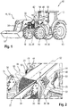
- FIG. 1 an agricultural working machine 10 in the form of a tractor is shown in a perspective view, wherein the basic structure of a tractor is considered to be known in the art.
- An agricultural working machine 10 in the sense of the invention can be any vehicle that can be used for agricultural work, for example a tractor, a front loader, a construction machine or a self-propelled harvesting machine such as a combine harvester or forage harvester.
- the tractor has for receiving an operator to a closed cab 12, wherein within the cab 12 an output unit 14 in the form of a display and control element for displaying information and / or to operate the agricultural machine 10 is arranged.
- FIG. 1 shown agricultural machine 10 in the form of a tractor is equipped with different recording devices 16, depending on how performing work to accommodate different attachments 18 can.
- the receiving devices 16 are in the form of an attachment bracket 20 for an attachment 18 in the form of a front loader 22, a hitch 24 and a rear side arranged linkage (not shown).
- a power lift 26, for example a three-point power lift, can be arranged on the agricultural machine 10 at the front and / or at the rear.
- a hitch 24 may be any device for receiving an attachment 18 such as a front loader 22, a harrow or a trailer.
- the hitch 24 may be formed, for example in the form of a bolt coupling, a tow hook, a coupling ball, a ball coupling or a drawbar.
- the agricultural machine 10 For working with straw bales, silage bales or for overburden crop, the agricultural machine 10 for receiving a front loader 22 attachment brackets 20 on which the front loader 22 is releasably fixed.
- the receiving consoles 20 are arranged substantially vertically on both sides of a covering element 58 of the working machine 10 in the form of an engine compartment lining 28.
- the engine compartment trim 28 can be mounted pivotably.
- a trim element 58 of the body 30 may be any displaceable or fixed trim of the body 30 of the agricultural work machine 10.
- the entire outer shape of the working machine 10 is to be understood, in particular those parts which could come into contact with the attachment 18 when receiving and / or settling an attachment 18, such as a chassis, tires, the Cabin 12, a receiving device 16, or the engine compartment lining 28.
- the front loader 22 has in addition to the actual working device, here in the form of a blade 32, two wings 34, which are each mounted in a mounting frame 36, in particular by hydraulic cylinders.
- the mounting frame 36 are each releasably connectable to the mounting brackets 20 of the machine 10.
- the tractor When picking up a parked front loader 22, the tractor must be moved as far between the mounting frame 36 and the wings 34 until the mounting frame 36 contact the mounting brackets 20.
- the mounting frame 36 and the wings 34 are thereby very close to the body 30 of the work machine 10, for example, between the engine compartment trim 28 and front wheels 40 of the work machine 10, along.
- To stop the front loader 22 is after its Loosen the tractor between the mounting frame 36 and the swing arm 34 to move out.
- this can be constructed in the form of a so-called Abstellfrontladers 22, which has hinged Abstell nun 38 on the wings 34, through which the front loader 22 can be placed in a position in which the mounting frame 36 substantially remain at a level in which they are attached to the mounting brackets 20.
- Abstellfrontladers 22 which has hinged Abstell nun 38 on the wings 34, through which the front loader 22 can be placed in a position in which the mounting frame 36 substantially remain at a level in which they are attached to the mounting brackets 20.
- the agricultural working machine 10 has a working machine-side arranged sensor system 42 with at least one sensor unit 44 and an evaluation unit 46, wherein by the sensor system 42, a relative position of the male and / or mounted attachment 18 relative to the working machine 10 can be determined.
- signals can be generated by the at least one sensor unit 44, which signals are received and evaluated by the evaluation unit 46.
- the evaluation unit 46 determines based on the signals of the at least one sensor unit 44, the relative position of the attachment 18.
- an output unit 14 the operator of the work machine 10, the specific relative position can be transmitted.
- the specific relative position can be transmitted to the operator, for example, by an acoustic and / or optical output unit 14.
- An optical output for example, via each one sensor unit 44 associated beam-shaped lights done, the luminous length, for example, the relative position, in particular a distance between the attachment 18 and body 30, dependent.
- an optical output via a pictorial representation of the relative position for example on an output unit 14 in the form of a display and control unit such as a terminal done.
- the sensor system 42 ( Fig. 2 ) has two sensor units 44, which are arranged on the front side in front of the mounting brackets 20, laterally on opposite sides of the engine compartment lining 28.
- the sensor units 44 each have a plurality of sensors 48, which may be formed, for example, in the form of ultrasonic sensors.
- the sensors 48 are arranged in a row, substantially perpendicular, in particular with an upper-side inclination toward the front of the work machine 10, laterally on the engine compartment lining 28.
- the arrangement of the sensors 48 in a row, the sensor units 44 each have an elongated extent, whereby a measuring range 50 of the sensor unit 44 also has an elongated, in particular substantially vertical, extension.
- the elongate extension and the substantial arrangement of the measuring area 50 has the advantage that the front loader 22 can be reliably detected by the sensor unit 44, regardless of the precise vertical arrangement of its rockers 34 and mounting frame 36.
- a geometric configuration of the measuring region 50 in particular a width and / or extension perpendicular to the body 30, may depend on the type of sensors 48 used in each case.
- a relative position of the front loader 22 to the body 30 of the work machine can be displayed to the operator.
- a distance of the front loader 22, in particular its rocker 34 and / or mounting frame 36, to the body 30 can be determined simultaneously on both sides of the engine compartment lining 28.
- the mutually determined distance between the body 30 and front loader 22 can be displayed to the operator together, so that a collision with the front loader 22 when approaching and / or driving away from the front loader 22 can be avoided.
- the sensor system 42 on the mounting brackets 20 each have a sensor unit 44.
- These sensor units 44 are each arranged and designed such that their measuring range is directed substantially parallel to a longitudinal axis 52 of the work machine 10 in the direction of the front loader 22.
- the measuring area 50 may be cylindrical, for example, in order to determine a distance d to the front loader 22, in particular a mounting frame 36 of the front loader 22, relative to the mounting bracket 20. This allows the operator reliably the distance d in the longitudinal direction between the front loader 22 and the attachment bracket 36, in particular the distance on the left side d L and the right side d R , are displayed.
- FIG. 3 is shown in a plan view of an agricultural machine 10 in the form of a tractor when receiving a parked front loader 22.
- the sensor system 42 on the engine compartment trim 28 has a sensor unit 44 arranged on each side.
- sensor units 44 each have a lateral distance x L, R of the front loader 22 to the body 30 and in particular to the engine compartment lining 28 can be determined.
- the distance d L, R in the longitudinal direction between the mounting brackets 20 and the mounting frame 36 of the front loader 22 can be determined by means of two sensor units 42 which are arranged on the mounting brackets 20 and aligned substantially parallel to the longitudinal axis 52 of the work machine 10 in the direction of the front loader 22 are.
- the agricultural working machine has a further receiving device 16 in the form of a rear-side arranged three-point power lift 54.
- a sensor unit 44 which is arranged, for example, on the driver's cab 12, can have a rear-side aligned measuring area (not shown) upon activation, by which a relative position of a working device (not shown) to be accommodated on the rear-side receiving device 16 can be determined.
- Modern agricultural machines 10 often have an automatic steering system 56, by which at least one automatic steering of the working machine 10 for tracking can be made possible. In addition, an automatic driving of the work machine 10 in both directions can be made possible by the steering system.
- the sensor system 42 in particular the evaluation unit 46, may be connected to such a steering system 56, so that approaching and / or driving away from an attachment 18, in particular in the form of a front loader 22, based on at least one determined by the sensor system 42 relative position of the attachment 18, can be automated.
- the determination of the relative position of an attachment 18 can be made continuously and / or at intervals, for example distance-dependent.
Landscapes
- Life Sciences & Earth Sciences (AREA)
- Zoology (AREA)
- Engineering & Computer Science (AREA)
- Mechanical Engineering (AREA)
- Soil Sciences (AREA)
- Environmental Sciences (AREA)
- Component Parts Of Construction Machinery (AREA)
Claims (9)
- Machine de travail agricole comprenant une carrosserie (30) qui comporte au moins un élément de garniture (58) et au moins un dispositif récepteur (16) pour recevoir un outil de travail (18), au moins un dispositif récepteur (16) étant conçu sous la forme d'une console de montage (20) pour un outil rapporté (18) en forme de chargeur frontal (22), un système de capteur (42) disposé côté machine de travail étant prévu avec au moins une unité de capteur (44) et une unité d'analyse (46), le système de capteur (42) permettant de déterminer une position relative d'un outil rapporté à recevoir et/ou à déposer (18) de la machine de travail (10) par rapport à la machine de travail (10), et la carrosserie (30) comportant une garniture de compartiment-moteur (28), caractérisée en ce qu'au moins une unité de capteur (44) est disposée sur la garniture de compartiment-moteur (28) pour la mesure latérale d'une distance (xL,R) de l'outil rapporté (18) à la carrosserie (30).
- Machine de travail selon la revendication 1, caractérisée en ce qu'une position relative de l'outil rapporté (18) par rapport à la machine de travail (10) peut être déterminée au moyen d'une mesure de distance.
- Machine de travail selon la revendication 1 ou 2, caractérisée en ce que le système de capteur (42) comporte au moins une unité de capteur (42) qui permet de mesurer une distance (xL,R, dL,R) d'un outil rapporté (18) par rapport à la carrosserie (30) dans une direction longitudinale.
- Machine de travail selon une des revendications précédentes, caractérisée en ce qu'au moins une unité de capteur (44) est disposée sur un dispositif récepteur (16, 20) et/ou sur une cabine de conduite (12) pour mesurer une distance (dL,R) dans la direction longitudinale.
- Machine de travail selon une des revendications précédentes, caractérisée en ce que l'unité de capteur (44) comporte au moins un capteur (48) qui fonctionne selon un principe de mesure acoustique, optoélectronique et/ou électromagnétique.
- Machine de travail selon une des revendications précédentes, caractérisée en ce que l'unité de capteur (44) comporte une plage de mesure (50), une configuration géométrique de la plage de mesure (50) pouvant être déterminée en fonction du nombre de capteurs (48), du type des capteurs (48) et/ou de l'agencement des capteurs (48).
- Machine de travail selon une des revendications précédentes, caractérisée en ce qu'il est prévu une unité de sortie (14) qui est reliée à l'unité d'analyse (46) et qui permet d'afficher, en particulier optiquement et/ou acoustiquement, une distance (xL,R, dL,R) entre la machine de travail (10) et un outil rapporté (18).
- Machine de travail selon une des revendications précédentes, caractérisée en ce qu'il est prévu un système de direction (54) qui est relié au système de capteur (42) et qui, lors d'une réception et/ou d'une dépose de l'outil rapporté (18), permet de diriger et/ou de déplacer automatiquement la machine de travail (10) sur la base des distances (xL,R, dL,R) déterminées par le système de capteur (42).
- Machine de travail selon une des revendications précédentes, caractérisée en ce qu'un dispositif récepteur (16) est une console de montage (20) pour un outil rapporté (18) en forme de relevage (54) et/ou de dispositif d'attelage (24).
Applications Claiming Priority (1)
| Application Number | Priority Date | Filing Date | Title |
|---|---|---|---|
| DE102015115704.7A DE102015115704A1 (de) | 2015-09-17 | 2015-09-17 | Landwirtschaftliche Arbeitsmaschine |
Publications (2)
| Publication Number | Publication Date |
|---|---|
| EP3143854A1 EP3143854A1 (fr) | 2017-03-22 |
| EP3143854B1 true EP3143854B1 (fr) | 2019-06-26 |
Family
ID=56321837
Family Applications (1)
| Application Number | Title | Priority Date | Filing Date |
|---|---|---|---|
| EP16177685.1A Not-in-force EP3143854B1 (fr) | 2015-09-17 | 2016-07-04 | Engin agricole |
Country Status (2)
| Country | Link |
|---|---|
| EP (1) | EP3143854B1 (fr) |
| DE (1) | DE102015115704A1 (fr) |
Families Citing this family (2)
| Publication number | Priority date | Publication date | Assignee | Title |
|---|---|---|---|---|
| DE102019206658B4 (de) | 2019-05-09 | 2026-03-05 | Zf Friedrichshafen Ag | Verfahren und Vorrichtung zur Getriebesteuerung einer Arbeitsmaschine |
| DE102019208998B4 (de) | 2019-06-19 | 2021-10-28 | Zf Friedrichshafen Ag | Antriebsstrang für eine Arbeitsmaschine und Verfahren zur Steuerung eines solchen Antriebsstrangs |
Family Cites Families (6)
| Publication number | Priority date | Publication date | Assignee | Title |
|---|---|---|---|---|
| DE3831212A1 (de) | 1988-09-14 | 1990-03-22 | Fendt & Co Xaver | Befestigung eines anbaugeraetes an einem arbeitsfahrzeug, insbesondere eines frontladers an einem ackerschlepper |
| DE10111529A1 (de) * | 2001-03-10 | 2002-09-12 | Deere & Co | Vorrichtung zum Koppeln eines Gerätes an einem Arbeitsfahrzeug |
| DE102006025698A1 (de) * | 2006-06-01 | 2007-12-06 | Alois Pöttinger Maschinenfabrik Gmbh | Verfahren und Vorrichtung zur Steuerung des Anspannens einer Landmaschine an einen Schlepper |
| US8191915B2 (en) * | 2008-10-17 | 2012-06-05 | GM Global Technology Operations LLC | Vehicle docking assistance system |
| US20120283909A1 (en) * | 2011-05-03 | 2012-11-08 | Dix Peter J | System and method for positioning a vehicle with a hitch using an automatic steering system |
| US9880560B2 (en) * | 2013-09-16 | 2018-01-30 | Deere & Company | Vehicle auto-motion control system |
-
2015
- 2015-09-17 DE DE102015115704.7A patent/DE102015115704A1/de not_active Withdrawn
-
2016
- 2016-07-04 EP EP16177685.1A patent/EP3143854B1/fr not_active Not-in-force
Non-Patent Citations (1)
| Title |
|---|
| None * |
Also Published As
| Publication number | Publication date |
|---|---|
| DE102015115704A1 (de) | 2017-03-23 |
| EP3143854A1 (fr) | 2017-03-22 |
Similar Documents
| Publication | Publication Date | Title |
|---|---|---|
| EP2042276B1 (fr) | Machine agricole et procédé de détermination de position | |
| EP2621257B1 (fr) | Combinaison constituée d'un véhicule tracteur et d'un appareil | |
| EP3017438B1 (fr) | Système anticollision pour un véhicule agricole avec détection automatique des dimensions d'une charge | |
| EP2893794B1 (fr) | Montage d'outil agricole | |
| EP2028072B1 (fr) | Véhicule automobile doté d'un système d'assistance au changement de voie ou de suivi de voie ainsi que d'un système d'aide au stationnement | |
| EP3251485A1 (fr) | Système et procédé de surveillance et/ou de contrôle de l'état de marche d'une machine de travail agricole automotrice | |
| EP3300558B1 (fr) | Dispositif et procédé de réglage du fonctionnement d'un appareil isolé hydraulique d'un véhicule | |
| EP3342264B1 (fr) | Dispositif et procédé de réglage du fonctionnement d'un véhicule avec un outil porté ou une remorque | |
| EP2042352B1 (fr) | Dispositif et procédé d'accouplement d'une remorque sur un véhicule de traction agricole | |
| DE102016117237A1 (de) | Verfahren zum mechanischen Koppeln eines Anbaugerätes mit einem Zugfahrzeug oder einer Anhängevorrichtung | |
| EP3915353B1 (fr) | Procédé de détermination de la position d'une caméra agencée sur un chargeur d'une moissonneuse autonome | |
| DE102011051827A1 (de) | Landwirtschaftliche Arbeitsmaschine mit einer Einrichtung zur Erfassung von deren Fahrzeugzuständen | |
| EP2620326B1 (fr) | Procédé et dispositif d'assistance d'accouplement d'une remorque | |
| EP3143854B1 (fr) | Engin agricole | |
| DE102005044485B4 (de) | Hinderniserkennungsvorrichtung für ein Zugfahrzeug sowie Verfahren zur Hinderniserkennung | |
| EP2520155A1 (fr) | Moissonneuse avec au moins un convoyeur transversal | |
| EP3815975B1 (fr) | Machine agricole autonome et procédé d'aide à la conduite d'une machine agricole autonome lors de la conduite de la machine agricole | |
| EP3533307A1 (fr) | Procédé de commande d'un bras supérieur hydraulique d'un attelage trois points | |
| EP1762861B1 (fr) | Procédé et dispositif de mesure de créneaux de stationnement d'un vehicule automobile | |
| EP3295779A1 (fr) | Bras supérieur d'attelage pour un bras de relevage à trois points d'un tracteur agricole | |
| DE102006046329B4 (de) | Arbeitsfahrzeug mit einer Kupplungsvorrichtung zum Anhängen eines Arbeitsgerätes | |
| EP3818797B1 (fr) | Combinaison d'appareil de travail agricole et appareil | |
| EP3725149B1 (fr) | Levier à force de pivotement | |
| EP1769671A1 (fr) | Unité de travail agricole avec une machine de travail et une unité de localisation | |
| WO2025098647A1 (fr) | Véhicule automobile |
Legal Events
| Date | Code | Title | Description |
|---|---|---|---|
| PUAI | Public reference made under article 153(3) epc to a published international application that has entered the european phase |
Free format text: ORIGINAL CODE: 0009012 |
|
| STAA | Information on the status of an ep patent application or granted ep patent |
Free format text: STATUS: THE APPLICATION HAS BEEN PUBLISHED |
|
| AK | Designated contracting states |
Kind code of ref document: A1 Designated state(s): AL AT BE BG CH CY CZ DE DK EE ES FI FR GB GR HR HU IE IS IT LI LT LU LV MC MK MT NL NO PL PT RO RS SE SI SK SM TR |
|
| AX | Request for extension of the european patent |
Extension state: BA ME |
|
| STAA | Information on the status of an ep patent application or granted ep patent |
Free format text: STATUS: REQUEST FOR EXAMINATION WAS MADE |
|
| 17P | Request for examination filed |
Effective date: 20170922 |
|
| RBV | Designated contracting states (corrected) |
Designated state(s): AL AT BE BG CH CY CZ DE DK EE ES FI FR GB GR HR HU IE IS IT LI LT LU LV MC MK MT NL NO PL PT RO RS SE SI SK SM TR |
|
| STAA | Information on the status of an ep patent application or granted ep patent |
Free format text: STATUS: EXAMINATION IS IN PROGRESS |
|
| 17Q | First examination report despatched |
Effective date: 20181018 |
|
| GRAP | Despatch of communication of intention to grant a patent |
Free format text: ORIGINAL CODE: EPIDOSNIGR1 |
|
| STAA | Information on the status of an ep patent application or granted ep patent |
Free format text: STATUS: GRANT OF PATENT IS INTENDED |
|
| INTG | Intention to grant announced |
Effective date: 20190409 |
|
| GRAS | Grant fee paid |
Free format text: ORIGINAL CODE: EPIDOSNIGR3 |
|
| GRAA | (expected) grant |
Free format text: ORIGINAL CODE: 0009210 |
|
| STAA | Information on the status of an ep patent application or granted ep patent |
Free format text: STATUS: THE PATENT HAS BEEN GRANTED |
|
| AK | Designated contracting states |
Kind code of ref document: B1 Designated state(s): AL AT BE BG CH CY CZ DE DK EE ES FI FR GB GR HR HU IE IS IT LI LT LU LV MC MK MT NL NO PL PT RO RS SE SI SK SM TR |
|
| REG | Reference to a national code |
Ref country code: GB Ref legal event code: FG4D Free format text: NOT ENGLISH |
|
| REG | Reference to a national code |
Ref country code: CH Ref legal event code: EP |
|
| REG | Reference to a national code |
Ref country code: AT Ref legal event code: REF Ref document number: 1147209 Country of ref document: AT Kind code of ref document: T Effective date: 20190715 |
|
| REG | Reference to a national code |
Ref country code: DE Ref legal event code: R096 Ref document number: 502016005212 Country of ref document: DE |
|
| REG | Reference to a national code |
Ref country code: IE Ref legal event code: FG4D Free format text: LANGUAGE OF EP DOCUMENT: GERMAN |
|
| REG | Reference to a national code |
Ref country code: NL Ref legal event code: MP Effective date: 20190626 |
|
| PG25 | Lapsed in a contracting state [announced via postgrant information from national office to epo] |
Ref country code: LT Free format text: LAPSE BECAUSE OF FAILURE TO SUBMIT A TRANSLATION OF THE DESCRIPTION OR TO PAY THE FEE WITHIN THE PRESCRIBED TIME-LIMIT Effective date: 20190626 Ref country code: FI Free format text: LAPSE BECAUSE OF FAILURE TO SUBMIT A TRANSLATION OF THE DESCRIPTION OR TO PAY THE FEE WITHIN THE PRESCRIBED TIME-LIMIT Effective date: 20190626 Ref country code: SE Free format text: LAPSE BECAUSE OF FAILURE TO SUBMIT A TRANSLATION OF THE DESCRIPTION OR TO PAY THE FEE WITHIN THE PRESCRIBED TIME-LIMIT Effective date: 20190626 Ref country code: NO Free format text: LAPSE BECAUSE OF FAILURE TO SUBMIT A TRANSLATION OF THE DESCRIPTION OR TO PAY THE FEE WITHIN THE PRESCRIBED TIME-LIMIT Effective date: 20190926 Ref country code: HR Free format text: LAPSE BECAUSE OF FAILURE TO SUBMIT A TRANSLATION OF THE DESCRIPTION OR TO PAY THE FEE WITHIN THE PRESCRIBED TIME-LIMIT Effective date: 20190626 Ref country code: AL Free format text: LAPSE BECAUSE OF FAILURE TO SUBMIT A TRANSLATION OF THE DESCRIPTION OR TO PAY THE FEE WITHIN THE PRESCRIBED TIME-LIMIT Effective date: 20190626 |
|
| REG | Reference to a national code |
Ref country code: LT Ref legal event code: MG4D |
|
| PG25 | Lapsed in a contracting state [announced via postgrant information from national office to epo] |
Ref country code: GR Free format text: LAPSE BECAUSE OF FAILURE TO SUBMIT A TRANSLATION OF THE DESCRIPTION OR TO PAY THE FEE WITHIN THE PRESCRIBED TIME-LIMIT Effective date: 20190927 Ref country code: RS Free format text: LAPSE BECAUSE OF FAILURE TO SUBMIT A TRANSLATION OF THE DESCRIPTION OR TO PAY THE FEE WITHIN THE PRESCRIBED TIME-LIMIT Effective date: 20190626 Ref country code: BG Free format text: LAPSE BECAUSE OF FAILURE TO SUBMIT A TRANSLATION OF THE DESCRIPTION OR TO PAY THE FEE WITHIN THE PRESCRIBED TIME-LIMIT Effective date: 20190926 Ref country code: LV Free format text: LAPSE BECAUSE OF FAILURE TO SUBMIT A TRANSLATION OF THE DESCRIPTION OR TO PAY THE FEE WITHIN THE PRESCRIBED TIME-LIMIT Effective date: 20190626 |
|
| PG25 | Lapsed in a contracting state [announced via postgrant information from national office to epo] |
Ref country code: EE Free format text: LAPSE BECAUSE OF FAILURE TO SUBMIT A TRANSLATION OF THE DESCRIPTION OR TO PAY THE FEE WITHIN THE PRESCRIBED TIME-LIMIT Effective date: 20190626 Ref country code: SK Free format text: LAPSE BECAUSE OF FAILURE TO SUBMIT A TRANSLATION OF THE DESCRIPTION OR TO PAY THE FEE WITHIN THE PRESCRIBED TIME-LIMIT Effective date: 20190626 Ref country code: PT Free format text: LAPSE BECAUSE OF FAILURE TO SUBMIT A TRANSLATION OF THE DESCRIPTION OR TO PAY THE FEE WITHIN THE PRESCRIBED TIME-LIMIT Effective date: 20191028 Ref country code: RO Free format text: LAPSE BECAUSE OF FAILURE TO SUBMIT A TRANSLATION OF THE DESCRIPTION OR TO PAY THE FEE WITHIN THE PRESCRIBED TIME-LIMIT Effective date: 20190626 Ref country code: CZ Free format text: LAPSE BECAUSE OF FAILURE TO SUBMIT A TRANSLATION OF THE DESCRIPTION OR TO PAY THE FEE WITHIN THE PRESCRIBED TIME-LIMIT Effective date: 20190626 Ref country code: NL Free format text: LAPSE BECAUSE OF FAILURE TO SUBMIT A TRANSLATION OF THE DESCRIPTION OR TO PAY THE FEE WITHIN THE PRESCRIBED TIME-LIMIT Effective date: 20190626 |
|
| PG25 | Lapsed in a contracting state [announced via postgrant information from national office to epo] |
Ref country code: SM Free format text: LAPSE BECAUSE OF FAILURE TO SUBMIT A TRANSLATION OF THE DESCRIPTION OR TO PAY THE FEE WITHIN THE PRESCRIBED TIME-LIMIT Effective date: 20190626 Ref country code: ES Free format text: LAPSE BECAUSE OF FAILURE TO SUBMIT A TRANSLATION OF THE DESCRIPTION OR TO PAY THE FEE WITHIN THE PRESCRIBED TIME-LIMIT Effective date: 20190626 Ref country code: IT Free format text: LAPSE BECAUSE OF FAILURE TO SUBMIT A TRANSLATION OF THE DESCRIPTION OR TO PAY THE FEE WITHIN THE PRESCRIBED TIME-LIMIT Effective date: 20190626 Ref country code: IS Free format text: LAPSE BECAUSE OF FAILURE TO SUBMIT A TRANSLATION OF THE DESCRIPTION OR TO PAY THE FEE WITHIN THE PRESCRIBED TIME-LIMIT Effective date: 20191026 |
|
| REG | Reference to a national code |
Ref country code: CH Ref legal event code: PL |
|
| PG25 | Lapsed in a contracting state [announced via postgrant information from national office to epo] |
Ref country code: TR Free format text: LAPSE BECAUSE OF FAILURE TO SUBMIT A TRANSLATION OF THE DESCRIPTION OR TO PAY THE FEE WITHIN THE PRESCRIBED TIME-LIMIT Effective date: 20190626 Ref country code: MC Free format text: LAPSE BECAUSE OF FAILURE TO SUBMIT A TRANSLATION OF THE DESCRIPTION OR TO PAY THE FEE WITHIN THE PRESCRIBED TIME-LIMIT Effective date: 20190626 |
|
| PG25 | Lapsed in a contracting state [announced via postgrant information from national office to epo] |
Ref country code: PL Free format text: LAPSE BECAUSE OF FAILURE TO SUBMIT A TRANSLATION OF THE DESCRIPTION OR TO PAY THE FEE WITHIN THE PRESCRIBED TIME-LIMIT Effective date: 20190626 Ref country code: DK Free format text: LAPSE BECAUSE OF FAILURE TO SUBMIT A TRANSLATION OF THE DESCRIPTION OR TO PAY THE FEE WITHIN THE PRESCRIBED TIME-LIMIT Effective date: 20190626 |
|
| PG25 | Lapsed in a contracting state [announced via postgrant information from national office to epo] |
Ref country code: LU Free format text: LAPSE BECAUSE OF NON-PAYMENT OF DUE FEES Effective date: 20190704 Ref country code: IS Free format text: LAPSE BECAUSE OF FAILURE TO SUBMIT A TRANSLATION OF THE DESCRIPTION OR TO PAY THE FEE WITHIN THE PRESCRIBED TIME-LIMIT Effective date: 20200224 Ref country code: LI Free format text: LAPSE BECAUSE OF NON-PAYMENT OF DUE FEES Effective date: 20190731 Ref country code: CH Free format text: LAPSE BECAUSE OF NON-PAYMENT OF DUE FEES Effective date: 20190731 |
|
| REG | Reference to a national code |
Ref country code: DE Ref legal event code: R097 Ref document number: 502016005212 Country of ref document: DE |
|
| PLBE | No opposition filed within time limit |
Free format text: ORIGINAL CODE: 0009261 |
|
| STAA | Information on the status of an ep patent application or granted ep patent |
Free format text: STATUS: NO OPPOSITION FILED WITHIN TIME LIMIT |
|
| PG2D | Information on lapse in contracting state deleted |
Ref country code: IS |
|
| PG25 | Lapsed in a contracting state [announced via postgrant information from national office to epo] |
Ref country code: IE Free format text: LAPSE BECAUSE OF NON-PAYMENT OF DUE FEES Effective date: 20190704 |
|
| 26N | No opposition filed |
Effective date: 20200603 |
|
| PG25 | Lapsed in a contracting state [announced via postgrant information from national office to epo] |
Ref country code: SI Free format text: LAPSE BECAUSE OF FAILURE TO SUBMIT A TRANSLATION OF THE DESCRIPTION OR TO PAY THE FEE WITHIN THE PRESCRIBED TIME-LIMIT Effective date: 20190626 |
|
| GBPC | Gb: european patent ceased through non-payment of renewal fee |
Effective date: 20200704 |
|
| PG25 | Lapsed in a contracting state [announced via postgrant information from national office to epo] |
Ref country code: GB Free format text: LAPSE BECAUSE OF NON-PAYMENT OF DUE FEES Effective date: 20200704 |
|
| PG25 | Lapsed in a contracting state [announced via postgrant information from national office to epo] |
Ref country code: CY Free format text: LAPSE BECAUSE OF FAILURE TO SUBMIT A TRANSLATION OF THE DESCRIPTION OR TO PAY THE FEE WITHIN THE PRESCRIBED TIME-LIMIT Effective date: 20190626 |
|
| PG25 | Lapsed in a contracting state [announced via postgrant information from national office to epo] |
Ref country code: HU Free format text: LAPSE BECAUSE OF FAILURE TO SUBMIT A TRANSLATION OF THE DESCRIPTION OR TO PAY THE FEE WITHIN THE PRESCRIBED TIME-LIMIT; INVALID AB INITIO Effective date: 20160704 Ref country code: MT Free format text: LAPSE BECAUSE OF FAILURE TO SUBMIT A TRANSLATION OF THE DESCRIPTION OR TO PAY THE FEE WITHIN THE PRESCRIBED TIME-LIMIT Effective date: 20190626 |
|
| PG25 | Lapsed in a contracting state [announced via postgrant information from national office to epo] |
Ref country code: MK Free format text: LAPSE BECAUSE OF FAILURE TO SUBMIT A TRANSLATION OF THE DESCRIPTION OR TO PAY THE FEE WITHIN THE PRESCRIBED TIME-LIMIT Effective date: 20190626 |
|
| REG | Reference to a national code |
Ref country code: AT Ref legal event code: MM01 Ref document number: 1147209 Country of ref document: AT Kind code of ref document: T Effective date: 20210704 |
|
| PG25 | Lapsed in a contracting state [announced via postgrant information from national office to epo] |
Ref country code: AT Free format text: LAPSE BECAUSE OF NON-PAYMENT OF DUE FEES Effective date: 20210704 |
|
| P01 | Opt-out of the competence of the unified patent court (upc) registered |
Effective date: 20230516 |
|
| PGFP | Annual fee paid to national office [announced via postgrant information from national office to epo] |
Ref country code: DE Payment date: 20240719 Year of fee payment: 9 |
|
| PGFP | Annual fee paid to national office [announced via postgrant information from national office to epo] |
Ref country code: BE Payment date: 20240719 Year of fee payment: 9 |
|
| PGFP | Annual fee paid to national office [announced via postgrant information from national office to epo] |
Ref country code: FR Payment date: 20240730 Year of fee payment: 9 |
|
| REG | Reference to a national code |
Ref country code: DE Ref legal event code: R119 Ref document number: 502016005212 Country of ref document: DE |
|
| REG | Reference to a national code |
Ref country code: BE Ref legal event code: MM Effective date: 20250731 |
|
| PG25 | Lapsed in a contracting state [announced via postgrant information from national office to epo] |
Ref country code: DE Free format text: LAPSE BECAUSE OF NON-PAYMENT OF DUE FEES Effective date: 20260203 |
|
| PG25 | Lapsed in a contracting state [announced via postgrant information from national office to epo] |
Ref country code: BE Free format text: LAPSE BECAUSE OF NON-PAYMENT OF DUE FEES Effective date: 20250731 |
|
| PG25 | Lapsed in a contracting state [announced via postgrant information from national office to epo] |
Ref country code: FR Free format text: LAPSE BECAUSE OF NON-PAYMENT OF DUE FEES Effective date: 20250731 |