EP3295871A1 - Procédés, dispositifs et techniques de détection d'escarres - Google Patents
Procédés, dispositifs et techniques de détection d'escarres Download PDFInfo
- Publication number
- EP3295871A1 EP3295871A1 EP17199005.4A EP17199005A EP3295871A1 EP 3295871 A1 EP3295871 A1 EP 3295871A1 EP 17199005 A EP17199005 A EP 17199005A EP 3295871 A1 EP3295871 A1 EP 3295871A1
- Authority
- EP
- European Patent Office
- Prior art keywords
- user
- orientation
- patient
- display unit
- sensor device
- Prior art date
- Legal status (The legal status is an assumption and is not a legal conclusion. Google has not performed a legal analysis and makes no representation as to the accuracy of the status listed.)
- Granted
Links
Images




Classifications
-
- A—HUMAN NECESSITIES
- A61—MEDICAL OR VETERINARY SCIENCE; HYGIENE
- A61B—DIAGNOSIS; SURGERY; IDENTIFICATION
- A61B5/00—Measuring for diagnostic purposes; Identification of persons
- A61B5/44—Detecting, measuring or recording for evaluating the integumentary system, e.g. skin, hair or nails
- A61B5/441—Skin evaluation, e.g. for skin disorder diagnosis
- A61B5/447—Skin evaluation, e.g. for skin disorder diagnosis specially adapted for aiding the prevention of ulcer or pressure sore development, i.e. before the ulcer or sore has developed
-
- A—HUMAN NECESSITIES
- A61—MEDICAL OR VETERINARY SCIENCE; HYGIENE
- A61B—DIAGNOSIS; SURGERY; IDENTIFICATION
- A61B5/00—Measuring for diagnostic purposes; Identification of persons
- A61B5/0002—Remote monitoring of patients using telemetry, e.g. transmission of vital signals via a communication network
- A61B5/0015—Remote monitoring of patients using telemetry, e.g. transmission of vital signals via a communication network characterised by features of the telemetry system
- A61B5/002—Monitoring the patient using a local or closed circuit, e.g. in a room or building
-
- A—HUMAN NECESSITIES
- A61—MEDICAL OR VETERINARY SCIENCE; HYGIENE
- A61B—DIAGNOSIS; SURGERY; IDENTIFICATION
- A61B5/00—Measuring for diagnostic purposes; Identification of persons
- A61B5/103—Measuring devices for testing the shape, pattern, colour, size or movement of the body or parts thereof, for diagnostic purposes
- A61B5/11—Measuring movement of the entire body or parts thereof, e.g. head or hand tremor or mobility of a limb
- A61B5/1113—Local tracking of patients, e.g. in a hospital or private home
- A61B5/1114—Tracking parts of the body
-
- A—HUMAN NECESSITIES
- A61—MEDICAL OR VETERINARY SCIENCE; HYGIENE
- A61B—DIAGNOSIS; SURGERY; IDENTIFICATION
- A61B5/00—Measuring for diagnostic purposes; Identification of persons
- A61B5/68—Arrangements of detecting, measuring or recording means, e.g. sensors, in relation to patient
- A61B5/6887—Arrangements of detecting, measuring or recording means, e.g. sensors, in relation to patient mounted on external non-worn devices, e.g. non-medical devices
- A61B5/6889—Rooms
-
- A—HUMAN NECESSITIES
- A61—MEDICAL OR VETERINARY SCIENCE; HYGIENE
- A61B—DIAGNOSIS; SURGERY; IDENTIFICATION
- A61B5/00—Measuring for diagnostic purposes; Identification of persons
- A61B5/68—Arrangements of detecting, measuring or recording means, e.g. sensors, in relation to patient
- A61B5/6887—Arrangements of detecting, measuring or recording means, e.g. sensors, in relation to patient mounted on external non-worn devices, e.g. non-medical devices
- A61B5/6891—Furniture
Definitions
- aspects of the present invention relate generally to systems, devices and methods for the detection of compromised tissue perfusion and other issues affecting the health of a patient, and more particularly relates to systems, devices and methods for such detection, communicating of relevant information to a host, and providing either appropriate guidance to a caregiver to facilitate proper management of the patient or device instructions for providing automated care.
- Pressure ulcers are very common and they represent a significant source of morbidity and mortality for patients.
- the prevalence of pressure ulcers in the US alone is estimated to be between 1 .5 and 3.0 million people, with two thirds of cases involving patients 70 or older.
- Pressure ulcers will initially appear as areas of red or pink skin discoloration, but these areas can quickly develop into open wounds if left untreated. Open wounds can lead to severe health complications by exposing patients to life-threatening infections.
- the primary goal in the treatment and prevention of pressure ulcers is to relieve pressure on and around affected tissues. Pressure relief can be accomplished by frequently changing the position of immobilized patients and by using support surfaces that minimize surface pressure.
- pressure management is the most critical aspect of any successful treatment program, it is also important to ensure that patients receive adequate nutrition, engage in daily exercise, and follow a good skin care and personal hygiene protocol.
- a patient-associated communicator (“PAC") is capable of sending and/or receiving wireless signals and determining its orientation relative to a patient and/or the environment.
- a plurality of environmental reference communicators (ERCs ) are distributed at fixed or known reference locations.
- the PACs communicate with one or more ERCs, permitting a specific PAC location to be determined.
- the PACs can be affixed to the patient, or can be a beacon or other device affixed to a patient bed.
- the PACs have indicia so that a user such as a caregiver can easily orient the sensor with respect to the patient.
- a camera in communication with either the PACs or the ERCs is used to visually document the presence, absence, current condition, or progression of pressure ulcers for a monitored patient. That data is logged and stored for appropriate analysis.
- Image standardization can be provided to permit visual data obtained from a camera to be standardized to, for example, improve documentation. Image characteristics that may need to be standardized include image orientation, viewing angle, viewing distance, brightness, color, etc. To assist in image standardization, a visual reference may be placed within the field of the image.
- PACs can, in some embodiments, include indicators such as LEDs that can indicate which side the patient is on, when a patient requires a turn, which area of the body has been exposed to the most pressure, which direction a patient should be turned onto, or when a patient has been turned sufficiently to satisfy a turning protocol or to depressurize a given area.
- patient self-roll or repositioning can be encouraged by various means, such as audio, visual or physical/tactile guidance.
- acceleration and orientation monitoring of the patient may be used to monitor for motion caused by an alternating pressure mattress.
- the monitoring system of the present invention by detecting patient accelerations, can determine if a patient is being repositioned sufficiently.
- the system can include a pressure measurement system which can produce a pressure map of reasonable precision that then feeds back to a support surface.
- the system can automatically calculate at least one suggested decompression threshold/interval.
- the decompression threshold/interval refers to the minimum amount of time that an area of the body needs to experience reduced pressure or no pressure in order to adequately re-profuse that area of the body, thereby preventing ischemia and tissue damage.
- the present invention can also detect system can also detect very low to no movement or situations in a patient, such as when the patient's breathing, heartbeat, and other physical motions have stopped.
- a badge, nametag, bracelet, or other wearable device which is recognized by the system of the present invention can be worn or carried by the caregiver.
- the caregiver is associated with one or more wearable devices, which each comprises an identifier (such as a name, number, code, etc.).
- the wearable device wirelessly transmits to base stations that are in known locations.
- the caregiver can communicate with the PAC by physical interaction, such as by tapping on the PAC to indicate a completed turn or other event.
- a wireless communicator is associated with a patient, referred to herein as a patient-associated communicator (PAC).
- the PAC comprises an antenna that is capable of sending or receiving wireless signals.
- the PAC also has a means for determining its orientation (including the orientation of the PAC's antenna) relative to a patient and/or the environment.
- Such means for determining the PAC's orientation include an accelerometer, gyroscope, or magnetometer.
- the PAC has a directional antenna.
- a PAC can communicate with one or more ERCs, and since the location of ERCs is known, the location of PACs can therefore be determined by analyzing the relationship of a PAC to the various ERCs. Since the approximate transmitting range of PACs and ERCs is known, an approximate location for a PAC can be determined simply by knowing which ERCs a PAC is communicating with. If a PAC is communicating with an ERC, then the PAC (and therefore the corresponding patient) must reside within the same general location as the ERC (defined by the transmitting range of the PAC/ERC). Patient location can be determined more accurately by analyzing time of flight, perceived signal strength, or via triangulation of a PAC relative to multiple ERCs. These methods are well known to those familiar in the art.
- the patient- associated communicator is physically attached to a patient, such as on the patient's anterior chest.
- a wireless communicator that is placed on the patient's anterior chest may transmit more effectively in an anterior direction, and less effectively in a posterior direction (since the signal may be attenuated by the body tissue).
- the antenna of the patient-associated communicator can be configured to be directional. Since the human body can have a variety of different shapes, sizes, tissue densities, etc. the amount of signal attenuation can vary from person to person.
- a radio-opaque backing can be applied to one or more sides of the communicator, such that wireless transmission occurs preferentially in one direction.
- a novel method for improving the accuracy of location tracking of a directional PAC by providing information regarding the orientation of the directional PAC relative to ERCs has a means for determining the orientation of its antenna relative to the patient and/or the environment.
- the orientation of the PAC's antenna can be determined using sensors such an accelerometer, gyroscopic sensor, and/or magnetometer.
- the PAC will communicate its spatial orientation relative to an ERC. With knowledge of the orientation of the PAC relative to the patient, the perceived signal strength can be more accurately analyzed to help determine the location of a PAC relative to ERCs.
- a system calibration step can be performed.
- a calibration step can be completed to determine the communication readings (signal strength, time of flight, etc.) from a PAC at a given location for all possible PAC orientations, or a subset of common orientations.
- This calibration step can be done with a calibrating unit that simulates the patient (at least in terms of RF or wireless transmission) and rotates through various different orientations.
- This calibration can be done for bed locations such that bed assignments to patients are automatically made.
- the calibration can also be done for other location of chairs, rooms, lounges, bathrooms to help determine location of a patient. If more than one location is possible after the location analysis, the user may be given a set of possible locations to choose from. This helps by narrowing down the choices to allow for simpler interaction with the system.
- the data of user entries and patient orientation analysis can be used for the system to learn over time to improve its location analysis. It can also be used for detecting, alert, or learning from new obstructions, such as furniture, etc. over time.
- the same orientation based location analysis can be used with time of flight or other location analysis as well.
- the same orientation based location analysis can be used for objects such as equipment as well.
- any object can be determined more accurately using the method and device described herein.
- equipment can be tagged with a communicator. The equipment will attenuate the signal in certain directions. Therefore, if the orientation of the communicator is known, the system can factor this information into the location mapping system to more accurately determine the location of the equipment.
- a user is presented with location information of the PAC.
- the system may have analyzed the location of the PAC incorrectly. A user can then enter the correct information. This corrected information can be used as data to help further train the system. Additional calibration steps can also be used.
- the system can act with no initial calibration, and a user enters the initial location and/or orientation information.
- the system uses one or more user inputs to train the system on the location and orientation information. If the system detects small changes in the communication signal information (signal strength, etc.) between the PAC and ERCs and the location information is still correct, the system can also use that data to train the system as to the range of acceptable signal information for a given location.
- the system can know the location information is correct, by getting confirming input from the user, by getting no corrections from the user, or by receiving position information that is consistent with expected data, etc.
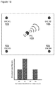
- a wireless communicator associated with each patient location.
- a communicator may be placed relative to each patient bed.
- the sufficiently close proximity between the patient sensor and the bed beacon/communicator will allow for automatic association between a patient and a bed.
- Proximity sensing can be done with various methods including signal strength or time or flight.
- the communication strength of the beacon or sensor can be small as well to prevent ambiguity of assignment, where a patient can be associated with more than one bed or a bed can be associated with more than one patient. If there is ambiguity, the assignment can be narrowed down to a few patients or beds to simplify the association process.
- the bed beacon can be plugged in or battery powered. It can be placed on the bed or the wall, as shown at 100 in Figure 8B . In some embodiments, the beacon can also display information visually or audibly.
- an embodiment in accordance with the present invention provides an improved method for photographic or videographic documentation of certain patient conditions, including skin lesions such as pressure ulcers.
- the PACs can be linked to a specific patient with one or more of the following:
- the camera can communicate with PACs located within transmitting range of the camera, for those implementations where the camera utilizes wireless communications.
- Data from the PACs i.e. patient name, MRN, etc.
- the camera can determine which PACs reside in closest proximity to the camera by analyzing perceived signal strength, time of flight, or other modalities known to those familiar with the art.
- the PACs enable an image to be automatically associated with a patient. This reduces the need for users to enter patient information manually and helps with workflow.
- the relative or absolute distance between the camera and PACs can also be determined.
- the communicating range of the camera and/or PACs can be modified such that more or fewer PACs become visible to the camera.
- the communicating range of the camera and/or PACs can be limited such that only a single PAC becomes visible to the camera.
- the camera may display a list of all possible PACs within communicating range of the camera or of the PACs that are closest to the camera. By displaying the nearby PACs, which may indicate that there are multiple patients that the system could automatically link an image to, the user can select the proper combination of image and medical record.
- the user may then select the PAC that is to be the focus of visual data collection. Any subsequent visual data collected by the camera (pictures, videos) is then automatically linked with data obtained from the selected PAC (i.e. patient name, MRN, etc.), and the linked data is sent to a central server for logging.
- the camera 200 may include a transmitter/transceiver that sends signals 215 to an environmental reference communication device or ERC 210 associated with a patient or the patient's room, to identify with whom any given visual data should be associated. Similar methods as noted above allow for the subject to be identified specifically when more than one ERC can be communicated with.
- the camera location either absolute or relative, can be identified and the determined location of the camera can be associated with the known location of a subject. The location can be identified by proximity to other known entities or locations. Alternatively, the location can be determined via means such as signal strength or time of flight analysis to other transmitters/ transceivers, including nodes, patient sensors 100, or GPS. Other sensors can be available on the camera including temperature, humidity, light sensors, audio sensors/microphones, orientation sensors, etc.
- a patient's name and/or demographic information can be automatically associated with images taken of the patient in real-time.
- One way this is accomplished is by having a wireless sensor associated with a specific patient.
- the sensor has a unique ID, which is then assigned to a patient.
- This assignment process can either be manual (i.e. manually assigning sensor ID to patient's MRN # in computer system) or automatic (i.e. barcode reader scans patient sensor and then patient ID bracelet).
- There are many ways of assigning the patient sensor to a specific patient which are well known to those familiar with the art.
- the camera or multimedia device
- the camera has a built-in wireless transceiver that can detect any patient sensors within its general proximity.
- the sensor ID and/or the name associated with said sensor
- the user selects the correct sensor ID (or patient name), and any pictures or images subsequently obtained are associated with the sensor/patient, until a new sensor/patient is selected.
- Figure 3 illustrates a further aspect of the invention, in which a plurality of transmitters 305 are positioned in fixed or known locations, and one or more sensors 300, each associated with a different patient, move within space observable by the camera 310.
- the camera location can be determined by triangulation with multiple base stations, and the accuracy of the camera location is improved by knowing the orientation of the transceiver on camera.
- patient location can be determined by triangulation with multiple base stations, again with accuracy improved by knowing the orientation of the transceiver, or communicator, on the associated patient. Because the camera is linked to the patient sensor, the camera and the sensor combination associates the visual data with the correct patent.
- the camera can upload the data it captures wirelessly to the system, such as via Bluetooth, Wifi, Zigbee or another established or custom wireless transfer protocol.
- the wireless transfer can be accomplished to a computer or computing station at the nursing station or other central location or it can be accomplished through an existing wireless network, such as the patient sensor network, Wifi, or communication node network.
- the data can also be transferred in a wired fashion, such as by USB, firewire, Ethernet, etc. Alternatively, the data can be transferred by other means such as by USB stick, memory card.
- the location of the image taken of skin or a pressure ulcer can be identified by the user. This can be accomplished by a list of locations or parameters to help define location, free text entry, or 2D or 3D image-based selection, where the user can, for instance, point to or drag and drop a location on a visual representation of the patient.
- a similar 2D or 3D representation can be used to identify areas that are at risk, have existing wounds, or have lines, etc., that be beneficial to avoid or target for repositioning.
- a visual reference 400 may be placed within the field of the image 405, as shown in Figure 4 .
- This visual reference can take the form of a sheet, ruler, or sticker of a known size, shape, and color.
- the visual reference may include standard reference lengths, colors, and orientation indicators.
- the camera, or other image processing functionality provided by the system can then process the image according to the appearance of the reference such that all images conform to the same standard.
- the reference may also take the form of a light source, as shown in Figure 5 .
- one or more lasers 500 can be shone from the camera unit, or from another source, onto the image.
- the laser light is directed towards the area of interest.
- the laser light may have a combination of features, including known size, shape, orientation, and spread. Image standardization can help better track the current condition and progression of an area of skin or a wound.
- laser light is focused on an area of interest (i.e. a pressure ulcer).
- the laser light has a matrix orientation as shown in Figure 5 , which is viewable by an associated camera 600. As the viewing distance increases, the area within individual squares of the matrix increases.
- the laser light also has one or more known wavelengths, such that the color can be standardized.
- the laser light may, but need not, have a wavelength in the visible spectrum as long as that wavelength can be viewed by the associated camera or other imaging device.
- an overlay 610 of a prior image can be projected onto the camera, also as shown in Figure 6 . The user can use this image overlay to help re-approximate viewing angle, distance, orientation, etc.
- indicators 700 on the sensor for example LEDs, which give information about the patient. These indicators may indicate which side the patient is on, when a patient requires a turn, which area of the body has been exposed to the most pressure, which direction a patient should be turned onto, or when a patient has been turned sufficiently to satisfy a turning protocol or to depressurize a given area. For example an LED on the left side may turn on when the patient is on their left side. Similarly, in another implementation or setting, the LED may be used to indicate when a patient should be turned and in which direction a patient should be turned. The LEDs may also indicate the relative pressurization levels at different body regions.
- the threshold of light would be exceeded when the caregiver lifts the sheets or clothing to view the sensor, and the LEDs would then come on.
- the wireless communication can be provided by the caregiver, either by sound or wireless communication generation.
- the caregiver can carry an RF transmitter that transmits a signal to the sensor when the caregiver is near or when the caregiver presses a button on his/her transmitter. The transmitted signal causes the indicators on the sensor to display.
- One or more of these methods can be used in combination either simultaneously or in spatial or temporal relation to one another.
- Certain stimuli may encourage the patient to turn away or towards without waking up or greatly disturbing sleep.
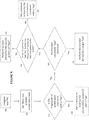
- the light or audio or physical stimuli are examples. Patients may naturally turn away from sound, lights, or nudges. In this way a patient may be encouraged to reposition according to a protocol or avoid pressure on certain areas. A patient self-turn reduces the need for caregiver interaction and promotes patient independence. If a patient does not reposition sufficiently, determined at 815, a caregiver can be notified as shown at 820.
- the stimuli for turning can be external to the patient sensors, such as a unit on the bed, as shown at 850 in Figure 8B .
- the caregiver can also carry components of the system with them.
- the caregiver has a badge, nametag, bracelet, or other wearable device which is recognized by the system of the present invention.
- the caregiver is associated with one or more wearable devices, which each comprises an identifier (such as a name, number, code, etc.).
- the wearable device wirelessly transmits to base stations that are in known locations.
- the system can determine when the caregiver is in a given room, provide information about when the caregiver is interacting with a patient or other caregiver, or can determine when the caregiver is in any particular location, such as a room, the nursing station, supply closet, or handwashing area.
- the location of the caregiver or indication of caregiver-patient interaction can be used to determine when a caregiver helps to reposition a patient. This can be used to determine who is repositioning a patient and to determine if sufficient self turns by the patient are being performed.
- Acceleration and orientation monitoring of the patient may be used to monitor for motion caused by an alternating pressure mattress.
- the monitoring system of the present invention by detecting patient accelerations, can determine if a patient is being repositioned sufficiently. Threshold acceleration values can be set, such that if the acceleration threshold is not met in a specified period of time, then it can be assumed that the patient is not being repositioned sufficiently.
- Alternating pressure mattresses utilize a series of inflatable air cells that inflate in a regular pattern, so as to encourage tissue depressurization of the subject lying on said alternating pressure mattress. This pattern of inflating/deflating air cells will generally cause rhythmic accelerations in a patient lying on the support surface.
- the caregiver wants to activate the PACs onboard LEDs (which can visually display data such as cumulative pressurization time on each side of the body), they can tap the PAC three times at ⁇ 1 Hz.
- the caregiver wants to activate the PACs onboard LEDs (which can visually display data such as cumulative pressurization time on each side of the body)
- they can tap the PAC three times at ⁇ 1 Hz.
- the system can monitor for characteristic movements associated with different indicators of sleep quality. These characteristics include apnea and movement, activity, or orientation during sleep. Reports can then be given about sleep quality to patients and caregivers.
- the system can include a pressure measurement system which can produce a pressure map of reasonable precision that then feeds back to a support surface.
- This pressure sensor system, feedback, and support surface can be a standalone system or it can interact with a sensor network. Knowing where pressure is higher than desired allows for a support surface to automatically respond by optimizing the pressure experienced by a patient. If the support surface is unable, by its automatic response means, to correct for the undesired pressure, it can alert a caregiver to decide about providing further care.
- the data can be used to inform treatment and parameters for care.
- DVT deep venous thrombosis
- a DVT is a blood clot that forms in a vein (typically in the leg veins) and often is a consequence of venous stasis, which can occur from prolonged immobility.
- Patients considered at risk for DVTs will generally receive DVT prophylaxis, which can be pharmacologic or mechanical in nature.
- Pharmacologic DVT prophylaxis consists of systemic anticoagulation (i.e. heparin, enoxaparin) which is delivered to patients via subcutaneous injections.
- Mechanical DVT prophylaxis consists of sequential compression devices (SCDs) which are pneumatic compression stockings that are affixed to the legs of patients and then inflate/deflate in order to promote blood flow and thereby prevent venous stasis.
- SCDs sequential compression devices
- a major risk factor for DVTs is prolonged immobility.
- the monitoring system of the present invention is designed to monitor a patient's movements and activity level, and the system can use this information to generate an 'activity index' value for a given patient, shown at steps 1000- 1075.
- the activity index value, shown at 1035 incorporates factors such as: total activity time, amplitude/frequency of movements, acceleration, sustained inactivity time (i.e. how long are the intervals between activity), etc.
- weighting for all of the variables can be customized by individual physicians, care providers or institutions, such that they can increase/decrease the threshold for DVT prophylaxis.
- a set of default values can be initially provided. The system is designed to help physicians objectively decide what treatment is best for their patients. Currently, physicians have limited objective information to understand how well a patient is ambulating.
- wireless communication via a device with an antenna can be affected by the surface upon which the antenna lies.
- a device on the surface of the skin can have its antenna performance affected by the electromagnetic and dielectric properties of the body.
- the device may have material between the body and the antenna that shields or reduces the relative effect of the body on the antenna performance.
- a material with a high dielectric constant can be placed on the device between the antenna and the body to serve this purpose.
- the system can automatically calculate at least one suggested decompression threshold/interval.
- the decompression threshold/interval refers to the minimum amount of time that an area of the body needs to experience reduced pressure or no pressure in order to adequately re-profuse that area of the body, thereby preventing ischemia and tissue damage. Once an area of the body has surpassed the suggested decompression threshold/interval, that area of the body can once again be pressurized with lower risk for causing tissue damage.
- the decompression threshold/interval can be calculated by taking into account factors selected from a group comprising: patient characteristics (i.e.
- patient variables mobility, activity, moisture, nutrition level, experienced or estimated sheer force, medical conditions, vital signs, health conditions, health status, previous skin conditions, and medications, etc.
- environmental factors type of bed surface, ambient temperature, humidity, etc.
- One or more calculation schemes can be used by the system and selected by the user.
- the system can also allow for a decompression threshold that is variable for any given patient.
- a decompression threshold that is variable for any given patient.
- One common usage is to have a decompression threshold for an area of the body vary with the amount of time the area of the body has experienced pressure.
- the decompression threshold can take the form of: D 0 + D 1 * duration of pressure where DO and D1 are constants that can be set or varied or vary automatically based on data about the patient or facility.
- the system, methods, and devices of the present invention provide an improved method for both calculating the appropriate decompression threshold/interval for a region of the body and also monitoring said region to determine when adequate decompression time has been achieved.
- Variables that may affect calculated decompression threshold include vitals (such as pulse ox, heart rate, breathing rate, blood pressure), time on a given side, duration of pressure orientation, existence of other wounds, patient characteristics (i.e. Braden score, age, comorbidities, size/weight/BM 1/body mass distribution, etc.), patient variables (mobility, activity, moisture, nutrition level, experienced or estimated sheer force, medical conditions, health conditions, health status, previous skin conditions, and medications, etc.), and environmental factors (type of bed surface, ambient temperature, humidity, treatment and prevention techniques used etc.).
- vitals such as pulse ox, heart rate, breathing rate, blood pressure
- time on a given side i.e. Braden score, age, comorbidities, size/weight/BM 1/body mass distribution, etc.
- patient variables mobility, activity, moisture, nutrition level, experienced or estimated sheer force, medical conditions, health conditions, health status, previous skin conditions, and medications, etc.
- environmental factors type of bed surface, ambient temperature, humidity, treatment and prevention techniques
- the system can also detect very low to no movement or situations in a patient. Such a situation occurs when the patient's breathing, heartbeat, and other physical motions have stopped. In such a case, the system can very quickly detect such a condition in the patient such that it can note the status and send an alert quickly. In certain cases it would be able to detect the situation in less than a few seconds or in less than one second and alert those who can provide help, possibly within enough time to help the patient. Detection can be much quicker than for systems that detect patient motions suggestive of an abnormal state such as arrhythmias and decompensation. In certain cases there may be ambient movement detected by the system that are not caused by the patient. These movements may easily be disregarded if they fall below the threshold for movements caused by heartbeat or breathing.
- the system may learn what movements are characteristic that don't arise from the patient.
- the system may utilize a separate sensor not on the patient to determine what movements are not arising from the patient and subtract those.
- the system may use sensors on more than one patient or more than one sensor on the same patient to subtract out the movements that are common, which may be subtracted as those movements arising from outside of the patient.
- Electrical signal detection from the patient can be used similarly and where movement is described above, electrical signals are replaced in another implementation of the system. Electrical signals and movement detection can be combined as well to further increase the accuracy and robustness of the detection.
Landscapes
- Health & Medical Sciences (AREA)
- Life Sciences & Earth Sciences (AREA)
- Engineering & Computer Science (AREA)
- Molecular Biology (AREA)
- Animal Behavior & Ethology (AREA)
- Biophysics (AREA)
- Pathology (AREA)
- Biomedical Technology (AREA)
- Heart & Thoracic Surgery (AREA)
- Medical Informatics (AREA)
- Veterinary Medicine (AREA)
- Surgery (AREA)
- Physics & Mathematics (AREA)
- General Health & Medical Sciences (AREA)
- Public Health (AREA)
- Computer Networks & Wireless Communication (AREA)
- Physiology (AREA)
- Dentistry (AREA)
- Oral & Maxillofacial Surgery (AREA)
- Dermatology (AREA)
- Measuring And Recording Apparatus For Diagnosis (AREA)
- Measurement Of The Respiration, Hearing Ability, Form, And Blood Characteristics Of Living Organisms (AREA)
- Medical Treatment And Welfare Office Work (AREA)
Applications Claiming Priority (3)
| Application Number | Priority Date | Filing Date | Title |
|---|---|---|---|
| US201361888078P | 2013-10-08 | 2013-10-08 | |
| PCT/US2014/059756 WO2015054423A1 (fr) | 2013-10-08 | 2014-10-08 | Procédés, dispositifs et techniques de détection d'escarres |
| EP14851948.1A EP3054846A4 (fr) | 2013-10-08 | 2014-10-08 | Procédés, dispositifs et techniques de détection d'escarres |
Related Parent Applications (1)
| Application Number | Title | Priority Date | Filing Date |
|---|---|---|---|
| EP14851948.1A Division EP3054846A4 (fr) | 2013-10-08 | 2014-10-08 | Procédés, dispositifs et techniques de détection d'escarres |
Publications (2)
| Publication Number | Publication Date |
|---|---|
| EP3295871A1 true EP3295871A1 (fr) | 2018-03-21 |
| EP3295871B1 EP3295871B1 (fr) | 2024-08-28 |
Family
ID=52813623
Family Applications (2)
| Application Number | Title | Priority Date | Filing Date |
|---|---|---|---|
| EP14851948.1A Withdrawn EP3054846A4 (fr) | 2013-10-08 | 2014-10-08 | Procédés, dispositifs et techniques de détection d'escarres |
| EP17199005.4A Active EP3295871B1 (fr) | 2013-10-08 | 2014-10-08 | Dispositif de détection d'escarres |
Family Applications Before (1)
| Application Number | Title | Priority Date | Filing Date |
|---|---|---|---|
| EP14851948.1A Withdrawn EP3054846A4 (fr) | 2013-10-08 | 2014-10-08 | Procédés, dispositifs et techniques de détection d'escarres |
Country Status (4)
| Country | Link |
|---|---|
| EP (2) | EP3054846A4 (fr) |
| JP (2) | JP6530746B2 (fr) |
| CA (1) | CA2926709C (fr) |
| WO (1) | WO2015054423A1 (fr) |
Families Citing this family (19)
| Publication number | Priority date | Publication date | Assignee | Title |
|---|---|---|---|---|
| US11278237B2 (en) | 2010-04-22 | 2022-03-22 | Leaf Healthcare, Inc. | Devices, systems, and methods for preventing, detecting, and treating pressure-induced ischemia, pressure ulcers, and other conditions |
| US10631732B2 (en) | 2009-03-24 | 2020-04-28 | Leaf Healthcare, Inc. | Systems and methods for displaying sensor-based user orientation information |
| US11272860B2 (en) | 2010-04-22 | 2022-03-15 | Leaf Healthcare, Inc. | Sensor device with a selectively activatable display |
| US11980449B2 (en) | 2010-04-22 | 2024-05-14 | Leaf Healthcare, Inc. | Systems and methods for monitoring orientation and biometric data using acceleration data |
| WO2017176667A1 (fr) * | 2010-04-22 | 2017-10-12 | Leaf Healthcare, Inc. | Procédés, dispositifs et techniques de détection d'escarres de décubitus |
| US10140837B2 (en) | 2010-04-22 | 2018-11-27 | Leaf Healthcare, Inc. | Systems, devices and methods for the prevention and treatment of pressure ulcers, bed exits, falls, and other conditions |
| US10588565B2 (en) | 2010-04-22 | 2020-03-17 | Leaf Healthcare, Inc. | Calibrated systems, devices and methods for preventing, detecting, and treating pressure-induced ischemia, pressure ulcers, and other conditions |
| US11051751B2 (en) | 2010-04-22 | 2021-07-06 | Leaf Healthcare, Inc. | Calibrated systems, devices and methods for preventing, detecting, and treating pressure-induced ischemia, pressure ulcers, and other conditions |
| JP6192032B2 (ja) | 2010-04-22 | 2017-09-06 | リーフ ヘルスケア インコーポレイテッド | 患者の生理学的状況をモニタリングするシステム |
| US9655546B2 (en) | 2010-04-22 | 2017-05-23 | Leaf Healthcare, Inc. | Pressure Ulcer Detection Methods, Devices and Techniques |
| US11369309B2 (en) | 2010-04-22 | 2022-06-28 | Leaf Healthcare, Inc. | Systems and methods for managing a position management protocol based on detected inclination angle of a person |
| US10758162B2 (en) | 2010-04-22 | 2020-09-01 | Leaf Healthcare, Inc. | Systems, devices and methods for analyzing a person status based at least on a detected orientation of the person |
| EP3474731B1 (fr) * | 2016-06-22 | 2024-02-28 | Leaf Healthcare, Inc. | Systèmes et procédés pour afficher des informations d'orientation d'utilisateur basées sur un capteur |
| US10842701B2 (en) | 2016-10-14 | 2020-11-24 | Stryker Corporation | Patient support apparatus with stabilization |
| US10339911B2 (en) | 2016-11-01 | 2019-07-02 | Stryker Corporation | Person support apparatuses with noise cancellation |
| CN111742374A (zh) * | 2017-12-28 | 2020-10-02 | 铁佑医疗控股私人有限公司 | 用于获得与创伤相关的数据的系统和方法 |
| CN112336307B (zh) * | 2020-10-30 | 2023-05-23 | 甘肃省人民医院 | 一种基于光学传感器对压力性损伤实时动态预防检测系统 |
| KR102707832B1 (ko) * | 2024-03-28 | 2024-09-25 | 주식회사 이노야드 | 이미지 처리 기반 얼굴 또는 신체의 3d 모델링 및 객체 추출 방법 |
| KR102727591B1 (ko) * | 2024-03-28 | 2024-11-11 | 주식회사 이노야드 | 이미지 처리 기반 상처 객체의 경계 및 상처 정보 생성 방법 |
Citations (3)
| Publication number | Priority date | Publication date | Assignee | Title |
|---|---|---|---|---|
| US20110263950A1 (en) * | 2010-04-22 | 2011-10-27 | Centauri Medical, INC. | Systems, devices and methods for preventing, detecting and treating pressure-induced ischemia, pressure ulcers, and other conditions |
| US20130090571A1 (en) * | 2011-10-06 | 2013-04-11 | The Board Of Regents Of The University Of Texas System | Methods and systems for monitoring and preventing pressure ulcers |
| US8436737B1 (en) * | 2012-03-13 | 2013-05-07 | Steelhead Innovations, Llc | Postural state attitude monitoring, caution, and warning systems and methods |
Family Cites Families (17)
| Publication number | Priority date | Publication date | Assignee | Title |
|---|---|---|---|---|
| JPH08238275A (ja) * | 1995-03-02 | 1996-09-17 | Yokohama Imeeji Syst:Kk | 床ずれ予防警報装置 |
| US6447460B1 (en) * | 1998-12-09 | 2002-09-10 | Kci Licensing, Inc. | Method for automated exclusion of deep venous thrombosis |
| US7378975B1 (en) * | 2000-06-09 | 2008-05-27 | Bed-Check Corporation | Method and apparatus for mitigating the risk of pressure sores |
| JP2004201758A (ja) * | 2002-12-24 | 2004-07-22 | ▲秦▼野 直 | 寝返り監視装置及びシステム並びに褥瘡予防方法 |
| JP4765087B2 (ja) * | 2005-05-23 | 2011-09-07 | 直 ▲秦▼野 | 寝返り管理システム |
| AU2008250975A1 (en) * | 2007-05-15 | 2008-11-20 | David Huber | Interactive patient system |
| WO2009046366A1 (fr) * | 2007-10-04 | 2009-04-09 | Alfred E. Mann Institute For Biomedical Engineering At The University Of Southern California | Procédé et appareil destinés à prévenir les escarres de décubitus et à les traiter |
| EP2285272A4 (fr) * | 2008-04-30 | 2017-01-04 | Board of Regents, The University of Texas System | Système intégré de lit de patient |
| EP2701131A2 (fr) * | 2008-05-12 | 2014-02-26 | Earlysense Ltd. | Surveiller, prévoir et traiter des épisodes cliniques |
| TWI363614B (en) * | 2008-09-17 | 2012-05-11 | Ind Tech Res Inst | Method and system for contour fitting and posture identification, and method for contour model adaptation |
| US10020075B2 (en) * | 2009-03-24 | 2018-07-10 | Leaf Healthcare, Inc. | Systems and methods for monitoring and/or managing patient orientation using a dynamically adjusted relief period |
| WO2013052123A1 (fr) * | 2011-10-03 | 2013-04-11 | Centauri Medical Inc. | Système et procédé permettant d'analyser l'orientation, l'emplacement et le mouvement de patients |
| WO2011087807A2 (fr) * | 2009-12-22 | 2011-07-21 | Health Discovery Corporation | Système et procédé de dépistage de mélanome à distance |
| JP5593746B2 (ja) * | 2010-03-11 | 2014-09-24 | アイシン精機株式会社 | 褥瘡発生リスク提示装置 |
| FR2969915B1 (fr) * | 2011-01-04 | 2014-01-03 | Ergylink | Systeme et procede pour analyser au moins une caracteristique de la peau |
| JP5767833B2 (ja) * | 2011-03-09 | 2015-08-19 | 株式会社日立製作所 | 臥位推定装置、臥位推定システム及び臥位推定方法 |
| US9427177B2 (en) * | 2011-04-11 | 2016-08-30 | Fidelity Investment Corporation | Fall detection methods and devices |
-
2014
- 2014-10-08 CA CA2926709A patent/CA2926709C/fr active Active
- 2014-10-08 EP EP14851948.1A patent/EP3054846A4/fr not_active Withdrawn
- 2014-10-08 EP EP17199005.4A patent/EP3295871B1/fr active Active
- 2014-10-08 JP JP2016521960A patent/JP6530746B2/ja active Active
- 2014-10-08 WO PCT/US2014/059756 patent/WO2015054423A1/fr not_active Ceased
-
2019
- 2019-05-17 JP JP2019093660A patent/JP6599580B1/ja active Active
Patent Citations (3)
| Publication number | Priority date | Publication date | Assignee | Title |
|---|---|---|---|---|
| US20110263950A1 (en) * | 2010-04-22 | 2011-10-27 | Centauri Medical, INC. | Systems, devices and methods for preventing, detecting and treating pressure-induced ischemia, pressure ulcers, and other conditions |
| US20130090571A1 (en) * | 2011-10-06 | 2013-04-11 | The Board Of Regents Of The University Of Texas System | Methods and systems for monitoring and preventing pressure ulcers |
| US8436737B1 (en) * | 2012-03-13 | 2013-05-07 | Steelhead Innovations, Llc | Postural state attitude monitoring, caution, and warning systems and methods |
Also Published As
| Publication number | Publication date |
|---|---|
| JP6599580B1 (ja) | 2019-10-30 |
| WO2015054423A1 (fr) | 2015-04-16 |
| EP3295871B1 (fr) | 2024-08-28 |
| EP3054846A4 (fr) | 2017-10-18 |
| JP2020014833A (ja) | 2020-01-30 |
| JP6530746B2 (ja) | 2019-06-12 |
| EP3054846A1 (fr) | 2016-08-17 |
| CA2926709A1 (fr) | 2015-04-16 |
| CA2926709C (fr) | 2023-01-24 |
| JP2016538900A (ja) | 2016-12-15 |
Similar Documents
| Publication | Publication Date | Title |
|---|---|---|
| US10004447B2 (en) | Systems and methods for collecting and displaying user orientation information on a user-worn sensor device | |
| EP3295871B1 (fr) | Dispositif de détection d'escarres | |
| US12133717B2 (en) | Systems and methods for patient fall detection | |
| US12521039B2 (en) | Systems and methods for monitoring orientation to reduce pressure ulcer formation | |
| US20230000396A1 (en) | Systems and methods for detecting movement | |
| US8647268B2 (en) | Patient monitoring apparatus | |
| US7502498B2 (en) | Patient monitoring apparatus | |
| CA3067778C (fr) | Surveillance de frequence cardiaque sans contact | |
| CA3019931A1 (fr) | Procedes, dispositifs et techniques de detection d'escarres de decubitus | |
| US20240225481A1 (en) | Patient monitoring system | |
| JP2019513457A (ja) | 褥瘡検出方法、デバイスおよび技法 |
Legal Events
| Date | Code | Title | Description |
|---|---|---|---|
| PUAI | Public reference made under article 153(3) epc to a published international application that has entered the european phase |
Free format text: ORIGINAL CODE: 0009012 |
|
| STAA | Information on the status of an ep patent application or granted ep patent |
Free format text: STATUS: THE APPLICATION HAS BEEN PUBLISHED |
|
| AC | Divisional application: reference to earlier application |
Ref document number: 3054846 Country of ref document: EP Kind code of ref document: P |
|
| AK | Designated contracting states |
Kind code of ref document: A1 Designated state(s): AL AT BE BG CH CY CZ DE DK EE ES FI FR GB GR HR HU IE IS IT LI LT LU LV MC MK MT NL NO PL PT RO RS SE SI SK SM TR |
|
| STAA | Information on the status of an ep patent application or granted ep patent |
Free format text: STATUS: REQUEST FOR EXAMINATION WAS MADE |
|
| 17P | Request for examination filed |
Effective date: 20180921 |
|
| RBV | Designated contracting states (corrected) |
Designated state(s): AL AT BE BG CH CY CZ DE DK EE ES FI FR GB GR HR HU IE IS IT LI LT LU LV MC MK MT NL NO PL PT RO RS SE SI SK SM TR |
|
| STAA | Information on the status of an ep patent application or granted ep patent |
Free format text: STATUS: EXAMINATION IS IN PROGRESS |
|
| 17Q | First examination report despatched |
Effective date: 20211222 |
|
| GRAP | Despatch of communication of intention to grant a patent |
Free format text: ORIGINAL CODE: EPIDOSNIGR1 |
|
| STAA | Information on the status of an ep patent application or granted ep patent |
Free format text: STATUS: GRANT OF PATENT IS INTENDED |
|
| RIC1 | Information provided on ipc code assigned before grant |
Ipc: A61B 5/00 20060101ALN20240306BHEP Ipc: A61B 5/11 20060101AFI20240306BHEP |
|
| INTG | Intention to grant announced |
Effective date: 20240327 |
|
| P01 | Opt-out of the competence of the unified patent court (upc) registered |
Effective date: 20240404 |
|
| GRAS | Grant fee paid |
Free format text: ORIGINAL CODE: EPIDOSNIGR3 |
|
| GRAA | (expected) grant |
Free format text: ORIGINAL CODE: 0009210 |
|
| STAA | Information on the status of an ep patent application or granted ep patent |
Free format text: STATUS: THE PATENT HAS BEEN GRANTED |
|
| AC | Divisional application: reference to earlier application |
Ref document number: 3054846 Country of ref document: EP Kind code of ref document: P |
|
| AK | Designated contracting states |
Kind code of ref document: B1 Designated state(s): AL AT BE BG CH CY CZ DE DK EE ES FI FR GB GR HR HU IE IS IT LI LT LU LV MC MK MT NL NO PL PT RO RS SE SI SK SM TR |
|
| REG | Reference to a national code |
Ref country code: GB Ref legal event code: FG4D |
|
| REG | Reference to a national code |
Ref country code: CH Ref legal event code: EP |
|
| REG | Reference to a national code |
Ref country code: DE Ref legal event code: R096 Ref document number: 602014090784 Country of ref document: DE |
|
| REG | Reference to a national code |
Ref country code: IE Ref legal event code: FG4D |
|
| REG | Reference to a national code |
Ref country code: LT Ref legal event code: MG9D |
|
| PG25 | Lapsed in a contracting state [announced via postgrant information from national office to epo] |
Ref country code: NO Free format text: LAPSE BECAUSE OF FAILURE TO SUBMIT A TRANSLATION OF THE DESCRIPTION OR TO PAY THE FEE WITHIN THE PRESCRIBED TIME-LIMIT Effective date: 20241128 |
|
| REG | Reference to a national code |
Ref country code: AT Ref legal event code: MK05 Ref document number: 1717051 Country of ref document: AT Kind code of ref document: T Effective date: 20240828 |
|
| PG25 | Lapsed in a contracting state [announced via postgrant information from national office to epo] |
Ref country code: NL Free format text: LAPSE BECAUSE OF FAILURE TO SUBMIT A TRANSLATION OF THE DESCRIPTION OR TO PAY THE FEE WITHIN THE PRESCRIBED TIME-LIMIT Effective date: 20240828 Ref country code: PT Free format text: LAPSE BECAUSE OF FAILURE TO SUBMIT A TRANSLATION OF THE DESCRIPTION OR TO PAY THE FEE WITHIN THE PRESCRIBED TIME-LIMIT Effective date: 20241230 Ref country code: GR Free format text: LAPSE BECAUSE OF FAILURE TO SUBMIT A TRANSLATION OF THE DESCRIPTION OR TO PAY THE FEE WITHIN THE PRESCRIBED TIME-LIMIT Effective date: 20241129 Ref country code: PL Free format text: LAPSE BECAUSE OF FAILURE TO SUBMIT A TRANSLATION OF THE DESCRIPTION OR TO PAY THE FEE WITHIN THE PRESCRIBED TIME-LIMIT Effective date: 20240828 Ref country code: FI Free format text: LAPSE BECAUSE OF FAILURE TO SUBMIT A TRANSLATION OF THE DESCRIPTION OR TO PAY THE FEE WITHIN THE PRESCRIBED TIME-LIMIT Effective date: 20240828 |
|
| PG25 | Lapsed in a contracting state [announced via postgrant information from national office to epo] |
Ref country code: BG Free format text: LAPSE BECAUSE OF FAILURE TO SUBMIT A TRANSLATION OF THE DESCRIPTION OR TO PAY THE FEE WITHIN THE PRESCRIBED TIME-LIMIT Effective date: 20240828 |
|
| PG25 | Lapsed in a contracting state [announced via postgrant information from national office to epo] |
Ref country code: LV Free format text: LAPSE BECAUSE OF FAILURE TO SUBMIT A TRANSLATION OF THE DESCRIPTION OR TO PAY THE FEE WITHIN THE PRESCRIBED TIME-LIMIT Effective date: 20240828 |
|
| REG | Reference to a national code |
Ref country code: NL Ref legal event code: MP Effective date: 20240828 |
|
| PG25 | Lapsed in a contracting state [announced via postgrant information from national office to epo] |
Ref country code: AT Free format text: LAPSE BECAUSE OF FAILURE TO SUBMIT A TRANSLATION OF THE DESCRIPTION OR TO PAY THE FEE WITHIN THE PRESCRIBED TIME-LIMIT Effective date: 20240828 Ref country code: IS Free format text: LAPSE BECAUSE OF FAILURE TO SUBMIT A TRANSLATION OF THE DESCRIPTION OR TO PAY THE FEE WITHIN THE PRESCRIBED TIME-LIMIT Effective date: 20241228 |
|
| PG25 | Lapsed in a contracting state [announced via postgrant information from national office to epo] |
Ref country code: HR Free format text: LAPSE BECAUSE OF FAILURE TO SUBMIT A TRANSLATION OF THE DESCRIPTION OR TO PAY THE FEE WITHIN THE PRESCRIBED TIME-LIMIT Effective date: 20240828 |
|
| PG25 | Lapsed in a contracting state [announced via postgrant information from national office to epo] |
Ref country code: ES Free format text: LAPSE BECAUSE OF FAILURE TO SUBMIT A TRANSLATION OF THE DESCRIPTION OR TO PAY THE FEE WITHIN THE PRESCRIBED TIME-LIMIT Effective date: 20240828 Ref country code: RS Free format text: LAPSE BECAUSE OF FAILURE TO SUBMIT A TRANSLATION OF THE DESCRIPTION OR TO PAY THE FEE WITHIN THE PRESCRIBED TIME-LIMIT Effective date: 20241128 |
|
| PG25 | Lapsed in a contracting state [announced via postgrant information from national office to epo] |
Ref country code: RS Free format text: LAPSE BECAUSE OF FAILURE TO SUBMIT A TRANSLATION OF THE DESCRIPTION OR TO PAY THE FEE WITHIN THE PRESCRIBED TIME-LIMIT Effective date: 20241128 Ref country code: PT Free format text: LAPSE BECAUSE OF FAILURE TO SUBMIT A TRANSLATION OF THE DESCRIPTION OR TO PAY THE FEE WITHIN THE PRESCRIBED TIME-LIMIT Effective date: 20241230 Ref country code: PL Free format text: LAPSE BECAUSE OF FAILURE TO SUBMIT A TRANSLATION OF THE DESCRIPTION OR TO PAY THE FEE WITHIN THE PRESCRIBED TIME-LIMIT Effective date: 20240828 Ref country code: NO Free format text: LAPSE BECAUSE OF FAILURE TO SUBMIT A TRANSLATION OF THE DESCRIPTION OR TO PAY THE FEE WITHIN THE PRESCRIBED TIME-LIMIT Effective date: 20241128 Ref country code: NL Free format text: LAPSE BECAUSE OF FAILURE TO SUBMIT A TRANSLATION OF THE DESCRIPTION OR TO PAY THE FEE WITHIN THE PRESCRIBED TIME-LIMIT Effective date: 20240828 Ref country code: LV Free format text: LAPSE BECAUSE OF FAILURE TO SUBMIT A TRANSLATION OF THE DESCRIPTION OR TO PAY THE FEE WITHIN THE PRESCRIBED TIME-LIMIT Effective date: 20240828 Ref country code: IS Free format text: LAPSE BECAUSE OF FAILURE TO SUBMIT A TRANSLATION OF THE DESCRIPTION OR TO PAY THE FEE WITHIN THE PRESCRIBED TIME-LIMIT Effective date: 20241228 Ref country code: HR Free format text: LAPSE BECAUSE OF FAILURE TO SUBMIT A TRANSLATION OF THE DESCRIPTION OR TO PAY THE FEE WITHIN THE PRESCRIBED TIME-LIMIT Effective date: 20240828 Ref country code: GR Free format text: LAPSE BECAUSE OF FAILURE TO SUBMIT A TRANSLATION OF THE DESCRIPTION OR TO PAY THE FEE WITHIN THE PRESCRIBED TIME-LIMIT Effective date: 20241129 Ref country code: FI Free format text: LAPSE BECAUSE OF FAILURE TO SUBMIT A TRANSLATION OF THE DESCRIPTION OR TO PAY THE FEE WITHIN THE PRESCRIBED TIME-LIMIT Effective date: 20240828 Ref country code: ES Free format text: LAPSE BECAUSE OF FAILURE TO SUBMIT A TRANSLATION OF THE DESCRIPTION OR TO PAY THE FEE WITHIN THE PRESCRIBED TIME-LIMIT Effective date: 20240828 Ref country code: BG Free format text: LAPSE BECAUSE OF FAILURE TO SUBMIT A TRANSLATION OF THE DESCRIPTION OR TO PAY THE FEE WITHIN THE PRESCRIBED TIME-LIMIT Effective date: 20240828 Ref country code: AT Free format text: LAPSE BECAUSE OF FAILURE TO SUBMIT A TRANSLATION OF THE DESCRIPTION OR TO PAY THE FEE WITHIN THE PRESCRIBED TIME-LIMIT Effective date: 20240828 |
|
| PG25 | Lapsed in a contracting state [announced via postgrant information from national office to epo] |
Ref country code: SM Free format text: LAPSE BECAUSE OF FAILURE TO SUBMIT A TRANSLATION OF THE DESCRIPTION OR TO PAY THE FEE WITHIN THE PRESCRIBED TIME-LIMIT Effective date: 20240828 Ref country code: RO Free format text: LAPSE BECAUSE OF FAILURE TO SUBMIT A TRANSLATION OF THE DESCRIPTION OR TO PAY THE FEE WITHIN THE PRESCRIBED TIME-LIMIT Effective date: 20240828 Ref country code: DK Free format text: LAPSE BECAUSE OF FAILURE TO SUBMIT A TRANSLATION OF THE DESCRIPTION OR TO PAY THE FEE WITHIN THE PRESCRIBED TIME-LIMIT Effective date: 20240828 |
|
| PG25 | Lapsed in a contracting state [announced via postgrant information from national office to epo] |
Ref country code: EE Free format text: LAPSE BECAUSE OF FAILURE TO SUBMIT A TRANSLATION OF THE DESCRIPTION OR TO PAY THE FEE WITHIN THE PRESCRIBED TIME-LIMIT Effective date: 20240828 |
|
| PG25 | Lapsed in a contracting state [announced via postgrant information from national office to epo] |
Ref country code: CZ Free format text: LAPSE BECAUSE OF FAILURE TO SUBMIT A TRANSLATION OF THE DESCRIPTION OR TO PAY THE FEE WITHIN THE PRESCRIBED TIME-LIMIT Effective date: 20240828 |
|
| PG25 | Lapsed in a contracting state [announced via postgrant information from national office to epo] |
Ref country code: IT Free format text: LAPSE BECAUSE OF FAILURE TO SUBMIT A TRANSLATION OF THE DESCRIPTION OR TO PAY THE FEE WITHIN THE PRESCRIBED TIME-LIMIT Effective date: 20240828 Ref country code: SK Free format text: LAPSE BECAUSE OF FAILURE TO SUBMIT A TRANSLATION OF THE DESCRIPTION OR TO PAY THE FEE WITHIN THE PRESCRIBED TIME-LIMIT Effective date: 20240828 |
|
| REG | Reference to a national code |
Ref country code: CH Ref legal event code: PL Ref country code: DE Ref legal event code: R097 Ref document number: 602014090784 Country of ref document: DE |
|
| PLBE | No opposition filed within time limit |
Free format text: ORIGINAL CODE: 0009261 |
|
| STAA | Information on the status of an ep patent application or granted ep patent |
Free format text: STATUS: NO OPPOSITION FILED WITHIN TIME LIMIT |
|
| PG25 | Lapsed in a contracting state [announced via postgrant information from national office to epo] |
Ref country code: MC Free format text: LAPSE BECAUSE OF FAILURE TO SUBMIT A TRANSLATION OF THE DESCRIPTION OR TO PAY THE FEE WITHIN THE PRESCRIBED TIME-LIMIT Effective date: 20240828 |
|
| PG25 | Lapsed in a contracting state [announced via postgrant information from national office to epo] |
Ref country code: LU Free format text: LAPSE BECAUSE OF NON-PAYMENT OF DUE FEES Effective date: 20241008 Ref country code: BE Free format text: LAPSE BECAUSE OF NON-PAYMENT OF DUE FEES Effective date: 20241031 |
|
| PG25 | Lapsed in a contracting state [announced via postgrant information from national office to epo] |
Ref country code: CH Free format text: LAPSE BECAUSE OF NON-PAYMENT OF DUE FEES Effective date: 20241031 |
|
| 26N | No opposition filed |
Effective date: 20250530 |
|
| REG | Reference to a national code |
Ref country code: BE Ref legal event code: MM Effective date: 20241031 |
|
| PG25 | Lapsed in a contracting state [announced via postgrant information from national office to epo] |
Ref country code: SE Free format text: LAPSE BECAUSE OF FAILURE TO SUBMIT A TRANSLATION OF THE DESCRIPTION OR TO PAY THE FEE WITHIN THE PRESCRIBED TIME-LIMIT Effective date: 20240828 |
|
| PGFP | Annual fee paid to national office [announced via postgrant information from national office to epo] |
Ref country code: GB Payment date: 20250918 Year of fee payment: 12 |
|
| PGFP | Annual fee paid to national office [announced via postgrant information from national office to epo] |
Ref country code: FR Payment date: 20250922 Year of fee payment: 12 |
|
| PG25 | Lapsed in a contracting state [announced via postgrant information from national office to epo] |
Ref country code: IE Free format text: LAPSE BECAUSE OF NON-PAYMENT OF DUE FEES Effective date: 20241008 |
|
| PGFP | Annual fee paid to national office [announced via postgrant information from national office to epo] |
Ref country code: DE Payment date: 20250916 Year of fee payment: 12 |
|
| PG25 | Lapsed in a contracting state [announced via postgrant information from national office to epo] |
Ref country code: CY Free format text: LAPSE BECAUSE OF FAILURE TO SUBMIT A TRANSLATION OF THE DESCRIPTION OR TO PAY THE FEE WITHIN THE PRESCRIBED TIME-LIMIT; INVALID AB INITIO Effective date: 20141008 |
|
| PG25 | Lapsed in a contracting state [announced via postgrant information from national office to epo] |
Ref country code: HU Free format text: LAPSE BECAUSE OF FAILURE TO SUBMIT A TRANSLATION OF THE DESCRIPTION OR TO PAY THE FEE WITHIN THE PRESCRIBED TIME-LIMIT; INVALID AB INITIO Effective date: 20141008 |