EP3295996A1 - Procédé de surveillance d'un dispositif de déclenchement d'une installation de protection contre l'incendie au moyen d'un courant d'essai estampé cycliquement ainsi que dispositif de commande de mise hors feu - Google Patents
Procédé de surveillance d'un dispositif de déclenchement d'une installation de protection contre l'incendie au moyen d'un courant d'essai estampé cycliquement ainsi que dispositif de commande de mise hors feu Download PDFInfo
- Publication number
- EP3295996A1 EP3295996A1 EP17188096.6A EP17188096A EP3295996A1 EP 3295996 A1 EP3295996 A1 EP 3295996A1 EP 17188096 A EP17188096 A EP 17188096A EP 3295996 A1 EP3295996 A1 EP 3295996A1
- Authority
- EP
- European Patent Office
- Prior art keywords
- relay
- monitoring
- extinguishing
- fet
- switching element
- Prior art date
- Legal status (The legal status is an assumption and is not a legal conclusion. Google has not performed a legal analysis and makes no representation as to the accuracy of the status listed.)
- Granted
Links
Images
Classifications
-
- A—HUMAN NECESSITIES
- A62—LIFE-SAVING; FIRE-FIGHTING
- A62C—FIRE-FIGHTING
- A62C37/00—Control of fire-fighting equipment
- A62C37/50—Testing or indicating devices for determining the state of readiness of the equipment
-
- A—HUMAN NECESSITIES
- A62—LIFE-SAVING; FIRE-FIGHTING
- A62C—FIRE-FIGHTING
- A62C37/00—Control of fire-fighting equipment
- A62C37/36—Control of fire-fighting equipment an actuating signal being generated by a sensor separate from an outlet device
Definitions
- the invention relates to a method for monitoring a triggering device of a fire extinguishing system.
- the triggering device such as a solenoid valve or pyrotechnic release, is connected via a supply line to a extinguishing control panel. It can also be connected in series several such tripping devices.
- the triggering device activates a pressurized extinguishing agent, such as a fire extinguisher. Nitrogen, released from an extinguishing agent container for fire extinguishing.
- extinguishing control center is also referred to as automatic control and delay device.
- the triggering device is triggered by the extinguishing control panel by means of a relay, wherein in series with the relay, a semiconductor switching element is connected in order to avoid a false triggering of the triggering device due to a mechanical action on the electromechanical relay.
- the switching contacts of a relay are typically operated as normally open.
- Relays are electromechanical components, but their switching contacts can close not only due to an electrical control voltage, but also due to mechanical effects.
- mechanical effects on the relays such as impact, impact, or construction, can cause the relay contacts to close with drill / hammer tools near them.
- the triggering device is energized, and it is triggered an unwanted deletion with the release of extinguishing agent.
- the triggering takes place only when both switching elements, i. both the relay and the semiconductor switching element are driven to close.
- the tripping device must be monitored for its functionality.
- Chap. 4.13.1 b stipulates that the cable routes to the tripping device are to be monitored for short-circuits as well as for interruptions.
- the semiconductor switching element in the event that no fire alarm is received, is repeatedly driven by the extinguishing control center in order to impress a (constant) test current for monitoring the connected tripping device via the supply line.
- This case that no fire alarm is received corresponds to the non-tripped state, ie the idle state, the extinguishing control center.
- the semiconductor switching element is driven cyclically, e.g. every 250 ms.
- the pulse duration of the impressed current is in particular in the range of 5 to 100 ms, typically in a range of 10 to 30 ms. A preferred value is 20 ms.
- the semiconductor switching element is typically a switching transistor. It is preferably a FET (for field effect transistor).
- the essence of the invention lies in the use of a wear-free switching means already present for triggering the tripping device for monitoring the same.
- the triggering device can be monitored in a particularly simple manner and more reliably.
- a processor-based control unit such as e.g. a microcontroller or a microcomputer.
- the program steps representing the method according to the invention in the form of a computer program can then be loaded and executed by the control unit as an application or such a computer program is already stored there non-volatilely for execution.
- an FPGA for Field Programmable Gate Array
- a control unit can be used as a control unit.
- the switching contacts of the relay are monitored by the extinguishing control center for closing.
- a first error message is issued when a closing of the switch contacts of the relay is signaled, although the relay is not activated by the extinguishing control panel. This is the typical case when the switching contacts of the relay close due to mechanical action.
- the first error message can be visually and / or acoustically displayed on the extinguishing control panel. It can alternatively or additionally be output via a connected bus, such as to a control center.
- the switching contacts of the relay are monitored by the extinguishing control center for closing. It is a possible control of the semiconductor switching element for closing the semiconductor switching element prevented when a closing of the switching contacts of the relay is reported, although the relay is not controlled by the extinguishing control panel. This locking advantageously further reduces the probability of a faulty triggering of the triggering device.
- a second error message is output when a monitoring voltage drop across the supply line with the tripping device deviates in an inadmissible manner from a predetermined comparison value.
- the second error message can be visually and / or acoustically displayed on the extinguishing control panel. It may alternatively or additionally be output via a connected bus, e.g. to a control center.
- An impermissible deviation is an indication that there is a short circuit or an interruption of the supply line. This is especially the case when the impermissible deviation is significant and occurs suddenly. In contrast, a slight deviation is an indication of a creeping short circuit or a creeping interruption.
- the object of the invention is further achieved with an extinguishing control center, which is set up for triggering a fire extinguishing system by means of a connected to the extinguishing control center via a supply line triggering device for triggering the fire extinguishing system.
- Such an extinguishing control center has an electronic control unit, an input for receiving a fire alarm, a first and second supply voltage level, a relay, a semiconductor switching element, an electrical connection for connecting the supply line with the triggering device, a current source for impressing a (constant) fürstroms in the connected Supply line with the tripping device via the electrical connection and a voltage measuring device for detecting a voltage applied to the electrical connection monitoring voltage.
- the control unit is preferably a microcontroller or an FPGA.
- the first supply voltage level is preferably positive with respect to the second supply voltage level. The latter can also be referred to as reference potential or as ground. At the first supply voltage level is typically a DC voltage in the range of 12 to 36 volts.
- the voltage measuring device may be, for example, a differential amplifier whose output is connected to an analog / digital converter.
- the electrical connection can be arranged in terms of circuitry in the middle of the series connection, while the first supply voltage level either the relay or the semiconductor switching element is switched and while the second supply voltage level either the semiconductor switching element or the relay is connected.
- the electrical connection can also be connected in terms of circuitry directly to the first or second supply voltage level.
- the sign of the voltage between the first and second supply voltage level is irrelevant.
- the charge carrier type is to be changed from an n-channel type to a p-channel type or vice versa.
- the control unit is configured or programmed to electrically actuate the relay and the semiconductor switching element to close the fire extinguishing system in the event a received fire alarm to trigger by means of the connected triggering device.
- control unit is configured, in the event that no fire alarm is received, repeatedly, in particular cyclically, to impress a (constant) test current for monitoring the tripping device connected via the supply line and to detect a monitoring voltage applied to the connection and to indicate an impermissible deviation to monitor.
- the circuitry complexity for monitoring the connected triggering device is significantly lower in the extinguishing control center according to the invention.
- the current source is sized to supply a current, typically a direct current, in a range of 1 to 20 mA.
- a preferred value is in the range of 3 to 6 mA.
- the resistance value is dimensioned such that a maximum of the aforementioned current values are established.
- the extinguishing control center on a connected to the switching contacts of the relay monitoring device. It is set up to output a monitoring signal in the event of (detected) closed switching contacts.
- the monitoring can be done by means of a resistance measuring device.
- the switching contacts provided for triggering further switching contacts of the relay, which are forcibly guided with former switching contacts, "queried" are. In this case, a switching voltage can be detected and evaluated.
- the erase control center has a logic unit which is adapted to receive first and second control signals from the control unit to it based on generating and outputting first and second switching signals for electrically driving the relay and the semiconductor device.
- the logic unit is also configured to output the second switching signal for the semiconductor switching element only when the first control signal and the monitoring signal are received.
- This circuit-based locking significantly reduces the probability of a false trip.
- the logic unit can be set up to output a first error message to the control unit when a monitoring signal and at the same time no first control signal are received. This error message can then be displayed acoustically and / or visually to a user.
- the extinguishing control center on a logic unit, which is adapted to receive a first, second and third control signal from the control unit to generate based thereon a first and second switching signal for electrically driving the relay and for driving the semiconductor switching element and issue.
- the logic unit is set up to output the second switching signal for the semiconductor switching element only when the third control signal and at the same time no monitoring signal are received.
- the functionality of the monitoring unit and / or that of the logic unit is integrated in the control unit, such as in a microcontroller or in an FPGA. This reduces the circuit complexity again.
- control unit is set up or programmed to detect the monitoring voltage applied to the terminal and to monitor it with a first comparison value at least for a creeping short circuit and with a second comparison value at least for a creeping interruption.
- control unit may have an already integrated A / D converter.
- the control unit is set up or programmed to output a second error message to the extinguishing control center and / or via a communication interface in the case of a respective undershoot or overshoot.
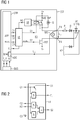
- FIG. 1 shows an exemplary extinguishing control center EST with attached triggering device AE according to the invention.
- the extinguishing control center EST has an electrical connection AN, to which a tripping device AE is connected.
- Such an electrically triggerable triggering device AE is, for example, a solenoid valve V or a pyrotechnic release PYR.
- a pyrotechnic trigger PYR is an electric ignitable detonator, as used in a similar manner when operating an airbag in a motor vehicle.
- a plunger is moved in the cylinder valve of the extinguishing agent container in order to release the outflow of the pressurized extinguishing agent.
- the ohmic resistance of a supply line not further indicated symbolizes.
- a supply line can be several meters to 100 meters long. Accordingly, the ohmic resistance increases with the same conductor cross-section of the supply line.
- the extinguishing control center EST shown has, for example, a single triggering channel K1. It is therefore a single-zone extinguishing control center.
- the extinguishing control center EST is designed as a multigrade extinguishing control center, then the at least one connected tripping device AE according to the standard VdS 2496, Chap. 4.3.2, to operate over a redundant line path.
- the extinguishing control unit shown EST two trip channels K1, K2, to trigger the connected triggering device AE in parallel.
- decoupling diodes D are required, which are connected in the respective supply line in series to the common trip device AE.
- the extinguisher control center EST has a microcontroller as the control unit CTR and a separate monitoring device UE and a separate logic unit LE.
- APP refers to a computer program running on the control unit CTR. This computer program APP represents an erase application.
- the monitoring device UE is set up to monitor the switching contacts of an electromechanical relay R for proper closing. It gives a corresponding monitoring signal KG, which is provided to the logic unit LE, for example, as a binary digital signal.
- the logic unit LE is arranged to receive first, second and third control signals C1, C2, C3 from the control unit CTR.
- a first and a second switching signal S1, S2 for the electrical activation of the relay R and of a semiconductor switching element FET.
- the latter is an example of a switching transistor (FET), which is connected in series with the relay R and in series with the electrical connection AN with the triggering device AE connected via the supply line.
- FET switching transistor
- the series connection of relay R, from the terminal AN with the triggering device AE connected via the supply line and from the semiconductor switching element FET is connected to a first supply voltage level V + and to a second supply voltage level V-.
- the voltage applied between the two supply voltage levels is typically in the range of 12 to 36 volts.
- the voltage is set so that when closing the two switching elements R, FET a tripping current iAE can be provided to reliably trigger the triggering device AE.
- the current values for the tripping current iAE are typically in a range of 0.5 to 2 amperes.
- the extinguishing control center EST has a (constant) current source IQ, which is set up to impress a test current iP in the tripping device AE via the supply line.
- the current source IQ may be in their technical design, for example, a current regulator or in the simplest case, an ohmic resistance.
- the test current iP is in the example of the present FIG. 1 fed in parallel to the two switching contacts of the relay R. Alternatively, it can also be fed to the terminals of the electrical connection AN. It is essential that the provided by the current source IQ Test current iP has a maximum current value, which is well below the current value for the tripping current iAE. It is preferably at least two orders of magnitude below the tripping current value.
- the test current iP preferably has current values in the range of a few milliamperes, in particular in a range of 3 to 6 mA.
- the semiconductor switching element FET is repeated in the event that no fire alarm AL is received, in particular cyclically, controlled by the extinguishing control center EST to impress a test current iP for monitoring the connected triggering device AE via the supply line.
- the already "anyway" existing semiconductor switching element FET is also used to turn on in addition to the triggering of the triggering device AE fire alarm AL cyclically and in comparison to the relay R wear-free the test current iP in the triggering device AE via the supply line.
- the connection is made several times a second, e.g. every 250 ms, and with a pulse duration preferably in a range of 10 to 30 ms. Due to the favorable ratio of switch-on time to switch-off time, the average power consumption for monitoring is comparatively low.
- the microcontroller CTR on which the deletion application APP is executed, is set up or programmed to receive a fire alarm AL via a connected communication interface BUS, such as via a P2 bus interface. If this is the case, the microcontroller CTR issues an audible and / or visual alarm in the area to be flooded in order to request any persons present there to leave this area. After a predetermined delay time, such as 10 seconds, the microcontroller CTR outputs the first and second control signal C1, C2. Both signals C1, C2 are output substantially simultaneously, such as a binary digital signal. They arrive at the logic unit LE, which generates and outputs based thereon two switching signals S1, S2 for the electrical control of the relay R and the semiconductor switching element FET.
- a constant test current iP is impressed via the supply line with the tripping device AE. It drops above this supply line from a monitoring voltage UM. If this deviates in an inadmissible manner from a predetermined comparison value, then a second error message F L is output. Their output is analogous to the output of the first error message F K.
- the detection of the falling at the supply line monitoring voltage UM is carried out in the example of FIG. 1 by means of a voltage measuring device MS.
- This converts the detected monitoring voltage UM into a suitable measuring voltage U M ' , which is suitable for electronic further processing.
- the voltage applied to the electrical terminal AN monitoring voltage UM is converted by means of a voltage divider MS to an electrical voltage U M ' , which is only a fraction of the detected monitoring voltage UM.
- This is converted into corresponding digital measured values M by an A / D converter ADC already integrated in the microcontroller CTR and monitored by the microcontroller CTR for monitoring for an impermissible deviation.
- corresponding digital comparison values are stored in the microcontroller CTR.
- the assigned digital measured value M falls below a first comparison value during the impressing of the constant test current iP, this is an indication on a creeping short.
- this is an indication of a (hard) short circuit.
- the assigned digital measured value M exceeds a second comparison value, then this is an indication of a (creeping) line interruption, since a greater electrical voltage drops due to the increase of the ohmic resistance along the supply line.
- the assigned digital measured value M exceeds a fourth comparison value, which is considerably larger in magnitude than the second comparison value, this is an indication of a complete line interruption.
- FIG. 2 shows the functional structure of an exemplary logic unit LE for the monitoring according to the invention in detail.
- the circuit logic shown can also be simulated by appropriate program steps and executed in the microcontroller CTR. It can also be integrated as such in an FPGA.
- both control signals C1, C2 having a logic level "1" are output by the microcontroller CTR and received by the logic unit LE.
- the first control signal C1 is internally processed, such as amplified by means of a transistor not further described, and output as electrical switching signal S1 to the relay R. If this closes, the logic unit LE receives from the monitoring device AE a monitoring signal KG with the logic level "1". This monitoring signal KG initially locks the third control signal C3 via the inverting input of the lower AND gate.
- the cyclically pulsed third control signal C3 which is provided for cyclically driving the semiconductor switching element FET for impressing a correspondingly pulsed test current iP, does not pass via the AND gate and also via the following OR gate to the second switching signal S2.
- the logic block LE In the event that the switching contacts of the relay R according to the invention close, although no first control signal S1 is output, the logic block LE outputs a first error message F K with the logic level "1". In this case, a logic "1" is applied to both inputs of the upper AND gate.
- the logic block LE each receives a logic level "0" for the two switching signals C1, C2. Then, the cyclically pulsed third control signal C3 is forwarded as the switching signal S2 for the semiconductor switching element FET when the monitoring signal KG has the logic level "0", ie when the relay contacts are open.
Landscapes
- Health & Medical Sciences (AREA)
- Public Health (AREA)
- Business, Economics & Management (AREA)
- Emergency Management (AREA)
- Fire Alarms (AREA)
Applications Claiming Priority (1)
| Application Number | Priority Date | Filing Date | Title |
|---|---|---|---|
| DE102016217909.8A DE102016217909B3 (de) | 2016-09-19 | 2016-09-19 | Verfahren zur Überwachung einer Auslöseeinrichtung einer Feuerlöschanlage mittels eines zyklisch eingeprägten Prüfstroms sowie Löschsteuerzentrale |
Publications (2)
| Publication Number | Publication Date |
|---|---|
| EP3295996A1 true EP3295996A1 (fr) | 2018-03-21 |
| EP3295996B1 EP3295996B1 (fr) | 2019-08-21 |
Family
ID=59713924
Family Applications (1)
| Application Number | Title | Priority Date | Filing Date |
|---|---|---|---|
| EP17188096.6A Active EP3295996B1 (fr) | 2016-09-19 | 2017-08-28 | Procédé de surveillance d'un dispositif de déclenchement d'une installation de protection contre l'incendie au moyen d'un courant d'essai estampé cycliquement ainsi que dispositif de commande de mise hors feu |
Country Status (2)
| Country | Link |
|---|---|
| EP (1) | EP3295996B1 (fr) |
| DE (1) | DE102016217909B3 (fr) |
Cited By (1)
| Publication number | Priority date | Publication date | Assignee | Title |
|---|---|---|---|---|
| CN115005702A (zh) * | 2021-03-04 | 2022-09-06 | 天津九安医疗电子股份有限公司 | 一种非接触式洗手机 |
Families Citing this family (1)
| Publication number | Priority date | Publication date | Assignee | Title |
|---|---|---|---|---|
| DE102023201838B4 (de) * | 2023-02-28 | 2024-10-02 | Siemens Schweiz Ag | Überwachte Stromversorgungseinheit, insbesondere zur Speisung von Komponenten eines Brand- oder Gefahrenmeldesystems |
Citations (3)
| Publication number | Priority date | Publication date | Assignee | Title |
|---|---|---|---|---|
| US4005754A (en) * | 1975-03-06 | 1977-02-01 | Gerhard Linden | Process for the automatic reporting and extinguishing of fires |
| US4410882A (en) * | 1979-06-13 | 1983-10-18 | Aktiebolaget Bofors | System for monitoring the ignition function of rapid extinguishing systems |
| DE3941109A1 (de) * | 1989-12-13 | 1991-06-20 | Henkel Kgaa | Steuerungssystem |
Family Cites Families (3)
| Publication number | Priority date | Publication date | Assignee | Title |
|---|---|---|---|---|
| US4101887A (en) | 1976-09-24 | 1978-07-18 | Walter Kidde And Co., Inc. | Monitored fire protection system |
| US5207276A (en) | 1991-04-25 | 1993-05-04 | Pem All Fire Extinguisher Corp. | Wire-sensored fire extinguisher with fault-monitoring control system |
| CA3010256C (fr) | 2012-06-26 | 2020-03-31 | Guardian Safety Solutions International Inc. | Systeme d'extinction d'incendie et methodes de diagnostic |
-
2016
- 2016-09-19 DE DE102016217909.8A patent/DE102016217909B3/de not_active Expired - Fee Related
-
2017
- 2017-08-28 EP EP17188096.6A patent/EP3295996B1/fr active Active
Patent Citations (3)
| Publication number | Priority date | Publication date | Assignee | Title |
|---|---|---|---|---|
| US4005754A (en) * | 1975-03-06 | 1977-02-01 | Gerhard Linden | Process for the automatic reporting and extinguishing of fires |
| US4410882A (en) * | 1979-06-13 | 1983-10-18 | Aktiebolaget Bofors | System for monitoring the ignition function of rapid extinguishing systems |
| DE3941109A1 (de) * | 1989-12-13 | 1991-06-20 | Henkel Kgaa | Steuerungssystem |
Cited By (1)
| Publication number | Priority date | Publication date | Assignee | Title |
|---|---|---|---|---|
| CN115005702A (zh) * | 2021-03-04 | 2022-09-06 | 天津九安医疗电子股份有限公司 | 一种非接触式洗手机 |
Also Published As
| Publication number | Publication date |
|---|---|
| EP3295996B1 (fr) | 2019-08-21 |
| DE102016217909B3 (de) | 2018-03-01 |
Similar Documents
| Publication | Publication Date | Title |
|---|---|---|
| DE69208799T2 (de) | Schutzschalter mit selektiver Verriegelung | |
| DE2833761C3 (de) | Schaltungsanordnung zur Überwachung des Zustands von Signalanlagen, insbesondere von Straßenverkehrs-Lichtsignalanlagen | |
| DE4441070C2 (de) | Sicherheitsschalteranordnung | |
| DE102008037302A1 (de) | Verfahren zum Überprüfen der Funktionsweise eines prozesstechnischen Feldgeräts und prozesstechnisches Feldgerät | |
| WO2019029763A1 (fr) | Module de pilotage et de surveillance | |
| EP3043220B1 (fr) | Dispositif et procede de surveillance fonctionnelle d'un moyen de commutation de securite | |
| EP2277154B1 (fr) | Dispositif de surveillance destiné à surveiller le fonctionnement d'un système de signalisation, système de signalisation et procédé de surveillance | |
| EP3295996B1 (fr) | Procédé de surveillance d'un dispositif de déclenchement d'une installation de protection contre l'incendie au moyen d'un courant d'essai estampé cycliquement ainsi que dispositif de commande de mise hors feu | |
| EP2546852B1 (fr) | Relais de sécurité bistable | |
| DE1513708C3 (de) | Phasenvergleich-Schutzanordnung | |
| DE2459175B2 (de) | Notalarmeinrichtung | |
| EP2117094B1 (fr) | Commutation de surveillance et procédé de contrôle d'une commutation | |
| EP0945950A2 (fr) | Procedéet dispositif pour contrÔler une charge | |
| DE102016218411A1 (de) | Verfahren zur Überwachung einer leitungsredundant angeschlossenen Reihenschaltung von pyrotechnischen Auslösern bei einer Feuerlöschanlage sowie Löschsteuerzentrale | |
| EP2988419B1 (fr) | Procede de determination de l'etat d'un element indicateur formant un court-circuit | |
| DE102014206366B4 (de) | Verfahren zur Prüfung eines Selbsthaltemagneten eines Schalters und Prüfeinrichtung für den Selbsthaltemagneten | |
| DE903349C (de) | Anordnung zur UEberwachung von mehreren Elementen in Betrieb befindlicher fernmeldetechnischer Einrichtungen, bei der der betriebsfaehige Zustand der Elemente aus dem Vorhandensein bestimmter Spannungen oder Stroeme erkennbar ist | |
| EP0730349B1 (fr) | Circuit à enclencher et déclencher une charge électrique | |
| EP3916940A1 (fr) | Agencement de circuit pourvu de disjoncteurs électroniques en cascade et procédé de mise en service de l'agencement de circuit | |
| DE730913C (de) | Meldeanlage fuer die UEbermittlung von Meldungen verschiedener Bedeutung und fuer die Herstellung von Fernsprechverbindungen ueber Schleifenleitungen | |
| DE2051793B2 (de) | Schaltungsanordnung zur leitungsueberwachung | |
| DE3036470C2 (de) | Anordnung zum Prüfen der Isolation einer im Bergbau unter Tage verlegten Hochspannungsversorgungsleitung | |
| DE2710046A1 (de) | Brandmeldesystem | |
| DE2629653B1 (de) | Loescheinrichtung | |
| DE102016012053A1 (de) | Schützeinrichtung für ein Kraftfahrzeug und Verfahren zum Überwachen einer Schützeinrichtung |
Legal Events
| Date | Code | Title | Description |
|---|---|---|---|
| PUAI | Public reference made under article 153(3) epc to a published international application that has entered the european phase |
Free format text: ORIGINAL CODE: 0009012 |
|
| STAA | Information on the status of an ep patent application or granted ep patent |
Free format text: STATUS: THE APPLICATION HAS BEEN PUBLISHED |
|
| AK | Designated contracting states |
Kind code of ref document: A1 Designated state(s): AL AT BE BG CH CY CZ DE DK EE ES FI FR GB GR HR HU IE IS IT LI LT LU LV MC MK MT NL NO PL PT RO RS SE SI SK SM TR |
|
| AX | Request for extension of the european patent |
Extension state: BA ME |
|
| STAA | Information on the status of an ep patent application or granted ep patent |
Free format text: STATUS: REQUEST FOR EXAMINATION WAS MADE |
|
| 17P | Request for examination filed |
Effective date: 20180918 |
|
| RBV | Designated contracting states (corrected) |
Designated state(s): AL AT BE BG CH CY CZ DE DK EE ES FI FR GB GR HR HU IE IS IT LI LT LU LV MC MK MT NL NO PL PT RO RS SE SI SK SM TR |
|
| GRAP | Despatch of communication of intention to grant a patent |
Free format text: ORIGINAL CODE: EPIDOSNIGR1 |
|
| STAA | Information on the status of an ep patent application or granted ep patent |
Free format text: STATUS: GRANT OF PATENT IS INTENDED |
|
| INTG | Intention to grant announced |
Effective date: 20190403 |
|
| GRAS | Grant fee paid |
Free format text: ORIGINAL CODE: EPIDOSNIGR3 |
|
| GRAA | (expected) grant |
Free format text: ORIGINAL CODE: 0009210 |
|
| STAA | Information on the status of an ep patent application or granted ep patent |
Free format text: STATUS: THE PATENT HAS BEEN GRANTED |
|
| AK | Designated contracting states |
Kind code of ref document: B1 Designated state(s): AL AT BE BG CH CY CZ DE DK EE ES FI FR GB GR HR HU IE IS IT LI LT LU LV MC MK MT NL NO PL PT RO RS SE SI SK SM TR |
|
| REG | Reference to a national code |
Ref country code: GB Ref legal event code: FG4D Free format text: NOT ENGLISH |
|
| REG | Reference to a national code |
Ref country code: CH Ref legal event code: EP |
|
| REG | Reference to a national code |
Ref country code: DE Ref legal event code: R096 Ref document number: 502017002071 Country of ref document: DE |
|
| REG | Reference to a national code |
Ref country code: AT Ref legal event code: REF Ref document number: 1169043 Country of ref document: AT Kind code of ref document: T Effective date: 20190915 |
|
| REG | Reference to a national code |
Ref country code: IE Ref legal event code: FG4D Free format text: LANGUAGE OF EP DOCUMENT: GERMAN |
|
| REG | Reference to a national code |
Ref country code: LT Ref legal event code: MG4D |
|
| REG | Reference to a national code |
Ref country code: NL Ref legal event code: MP Effective date: 20190821 |
|
| PG25 | Lapsed in a contracting state [announced via postgrant information from national office to epo] |
Ref country code: FI Free format text: LAPSE BECAUSE OF FAILURE TO SUBMIT A TRANSLATION OF THE DESCRIPTION OR TO PAY THE FEE WITHIN THE PRESCRIBED TIME-LIMIT Effective date: 20190821 Ref country code: NO Free format text: LAPSE BECAUSE OF FAILURE TO SUBMIT A TRANSLATION OF THE DESCRIPTION OR TO PAY THE FEE WITHIN THE PRESCRIBED TIME-LIMIT Effective date: 20191121 Ref country code: PT Free format text: LAPSE BECAUSE OF FAILURE TO SUBMIT A TRANSLATION OF THE DESCRIPTION OR TO PAY THE FEE WITHIN THE PRESCRIBED TIME-LIMIT Effective date: 20191223 Ref country code: BG Free format text: LAPSE BECAUSE OF FAILURE TO SUBMIT A TRANSLATION OF THE DESCRIPTION OR TO PAY THE FEE WITHIN THE PRESCRIBED TIME-LIMIT Effective date: 20191121 Ref country code: SE Free format text: LAPSE BECAUSE OF FAILURE TO SUBMIT A TRANSLATION OF THE DESCRIPTION OR TO PAY THE FEE WITHIN THE PRESCRIBED TIME-LIMIT Effective date: 20190821 Ref country code: NL Free format text: LAPSE BECAUSE OF FAILURE TO SUBMIT A TRANSLATION OF THE DESCRIPTION OR TO PAY THE FEE WITHIN THE PRESCRIBED TIME-LIMIT Effective date: 20190821 Ref country code: HR Free format text: LAPSE BECAUSE OF FAILURE TO SUBMIT A TRANSLATION OF THE DESCRIPTION OR TO PAY THE FEE WITHIN THE PRESCRIBED TIME-LIMIT Effective date: 20190821 Ref country code: LT Free format text: LAPSE BECAUSE OF FAILURE TO SUBMIT A TRANSLATION OF THE DESCRIPTION OR TO PAY THE FEE WITHIN THE PRESCRIBED TIME-LIMIT Effective date: 20190821 |
|
| PG25 | Lapsed in a contracting state [announced via postgrant information from national office to epo] |
Ref country code: IS Free format text: LAPSE BECAUSE OF FAILURE TO SUBMIT A TRANSLATION OF THE DESCRIPTION OR TO PAY THE FEE WITHIN THE PRESCRIBED TIME-LIMIT Effective date: 20191221 Ref country code: LV Free format text: LAPSE BECAUSE OF FAILURE TO SUBMIT A TRANSLATION OF THE DESCRIPTION OR TO PAY THE FEE WITHIN THE PRESCRIBED TIME-LIMIT Effective date: 20190821 Ref country code: RS Free format text: LAPSE BECAUSE OF FAILURE TO SUBMIT A TRANSLATION OF THE DESCRIPTION OR TO PAY THE FEE WITHIN THE PRESCRIBED TIME-LIMIT Effective date: 20190821 Ref country code: AL Free format text: LAPSE BECAUSE OF FAILURE TO SUBMIT A TRANSLATION OF THE DESCRIPTION OR TO PAY THE FEE WITHIN THE PRESCRIBED TIME-LIMIT Effective date: 20190821 Ref country code: ES Free format text: LAPSE BECAUSE OF FAILURE TO SUBMIT A TRANSLATION OF THE DESCRIPTION OR TO PAY THE FEE WITHIN THE PRESCRIBED TIME-LIMIT Effective date: 20190821 Ref country code: GR Free format text: LAPSE BECAUSE OF FAILURE TO SUBMIT A TRANSLATION OF THE DESCRIPTION OR TO PAY THE FEE WITHIN THE PRESCRIBED TIME-LIMIT Effective date: 20191122 |
|
| REG | Reference to a national code |
Ref country code: CH Ref legal event code: NV Representative=s name: SIEMENS SCHWEIZ AG, CH |
|
| REG | Reference to a national code |
Ref country code: DE Ref legal event code: R119 Ref document number: 502017002071 Country of ref document: DE |
|
| PG25 | Lapsed in a contracting state [announced via postgrant information from national office to epo] |
Ref country code: TR Free format text: LAPSE BECAUSE OF FAILURE TO SUBMIT A TRANSLATION OF THE DESCRIPTION OR TO PAY THE FEE WITHIN THE PRESCRIBED TIME-LIMIT Effective date: 20190821 |
|
| PG25 | Lapsed in a contracting state [announced via postgrant information from national office to epo] |
Ref country code: PL Free format text: LAPSE BECAUSE OF FAILURE TO SUBMIT A TRANSLATION OF THE DESCRIPTION OR TO PAY THE FEE WITHIN THE PRESCRIBED TIME-LIMIT Effective date: 20190821 Ref country code: EE Free format text: LAPSE BECAUSE OF FAILURE TO SUBMIT A TRANSLATION OF THE DESCRIPTION OR TO PAY THE FEE WITHIN THE PRESCRIBED TIME-LIMIT Effective date: 20190821 Ref country code: DK Free format text: LAPSE BECAUSE OF FAILURE TO SUBMIT A TRANSLATION OF THE DESCRIPTION OR TO PAY THE FEE WITHIN THE PRESCRIBED TIME-LIMIT Effective date: 20190821 Ref country code: IT Free format text: LAPSE BECAUSE OF FAILURE TO SUBMIT A TRANSLATION OF THE DESCRIPTION OR TO PAY THE FEE WITHIN THE PRESCRIBED TIME-LIMIT Effective date: 20190821 Ref country code: RO Free format text: LAPSE BECAUSE OF FAILURE TO SUBMIT A TRANSLATION OF THE DESCRIPTION OR TO PAY THE FEE WITHIN THE PRESCRIBED TIME-LIMIT Effective date: 20190821 |
|
| PG25 | Lapsed in a contracting state [announced via postgrant information from national office to epo] |
Ref country code: SM Free format text: LAPSE BECAUSE OF FAILURE TO SUBMIT A TRANSLATION OF THE DESCRIPTION OR TO PAY THE FEE WITHIN THE PRESCRIBED TIME-LIMIT Effective date: 20190821 Ref country code: CZ Free format text: LAPSE BECAUSE OF FAILURE TO SUBMIT A TRANSLATION OF THE DESCRIPTION OR TO PAY THE FEE WITHIN THE PRESCRIBED TIME-LIMIT Effective date: 20190821 Ref country code: MC Free format text: LAPSE BECAUSE OF FAILURE TO SUBMIT A TRANSLATION OF THE DESCRIPTION OR TO PAY THE FEE WITHIN THE PRESCRIBED TIME-LIMIT Effective date: 20190821 Ref country code: IS Free format text: LAPSE BECAUSE OF FAILURE TO SUBMIT A TRANSLATION OF THE DESCRIPTION OR TO PAY THE FEE WITHIN THE PRESCRIBED TIME-LIMIT Effective date: 20200224 Ref country code: LU Free format text: LAPSE BECAUSE OF NON-PAYMENT OF DUE FEES Effective date: 20190828 Ref country code: SK Free format text: LAPSE BECAUSE OF FAILURE TO SUBMIT A TRANSLATION OF THE DESCRIPTION OR TO PAY THE FEE WITHIN THE PRESCRIBED TIME-LIMIT Effective date: 20190821 |
|
| REG | Reference to a national code |
Ref country code: BE Ref legal event code: MM Effective date: 20190831 |
|
| PLBE | No opposition filed within time limit |
Free format text: ORIGINAL CODE: 0009261 |
|
| STAA | Information on the status of an ep patent application or granted ep patent |
Free format text: STATUS: NO OPPOSITION FILED WITHIN TIME LIMIT |
|
| PG2D | Information on lapse in contracting state deleted |
Ref country code: IS |
|
| PG25 | Lapsed in a contracting state [announced via postgrant information from national office to epo] |
Ref country code: IE Free format text: LAPSE BECAUSE OF NON-PAYMENT OF DUE FEES Effective date: 20190828 Ref country code: DE Free format text: LAPSE BECAUSE OF NON-PAYMENT OF DUE FEES Effective date: 20200303 |
|
| 26N | No opposition filed |
Effective date: 20200603 |
|
| PG25 | Lapsed in a contracting state [announced via postgrant information from national office to epo] |
Ref country code: SI Free format text: LAPSE BECAUSE OF FAILURE TO SUBMIT A TRANSLATION OF THE DESCRIPTION OR TO PAY THE FEE WITHIN THE PRESCRIBED TIME-LIMIT Effective date: 20190821 Ref country code: BE Free format text: LAPSE BECAUSE OF NON-PAYMENT OF DUE FEES Effective date: 20190831 |
|
| REG | Reference to a national code |
Ref country code: CH Ref legal event code: PL |
|
| PG25 | Lapsed in a contracting state [announced via postgrant information from national office to epo] |
Ref country code: LI Free format text: LAPSE BECAUSE OF NON-PAYMENT OF DUE FEES Effective date: 20200831 Ref country code: CH Free format text: LAPSE BECAUSE OF NON-PAYMENT OF DUE FEES Effective date: 20200831 |
|
| PG25 | Lapsed in a contracting state [announced via postgrant information from national office to epo] |
Ref country code: CY Free format text: LAPSE BECAUSE OF FAILURE TO SUBMIT A TRANSLATION OF THE DESCRIPTION OR TO PAY THE FEE WITHIN THE PRESCRIBED TIME-LIMIT Effective date: 20190821 |
|
| PG25 | Lapsed in a contracting state [announced via postgrant information from national office to epo] |
Ref country code: MT Free format text: LAPSE BECAUSE OF FAILURE TO SUBMIT A TRANSLATION OF THE DESCRIPTION OR TO PAY THE FEE WITHIN THE PRESCRIBED TIME-LIMIT Effective date: 20190821 Ref country code: HU Free format text: LAPSE BECAUSE OF FAILURE TO SUBMIT A TRANSLATION OF THE DESCRIPTION OR TO PAY THE FEE WITHIN THE PRESCRIBED TIME-LIMIT; INVALID AB INITIO Effective date: 20170828 |
|
| GBPC | Gb: european patent ceased through non-payment of renewal fee |
Effective date: 20210828 |
|
| PG25 | Lapsed in a contracting state [announced via postgrant information from national office to epo] |
Ref country code: MK Free format text: LAPSE BECAUSE OF FAILURE TO SUBMIT A TRANSLATION OF THE DESCRIPTION OR TO PAY THE FEE WITHIN THE PRESCRIBED TIME-LIMIT Effective date: 20190821 |
|
| PG25 | Lapsed in a contracting state [announced via postgrant information from national office to epo] |
Ref country code: GB Free format text: LAPSE BECAUSE OF NON-PAYMENT OF DUE FEES Effective date: 20210828 |
|
| P01 | Opt-out of the competence of the unified patent court (upc) registered |
Effective date: 20230523 |
|
| REG | Reference to a national code |
Ref country code: AT Ref legal event code: MM01 Ref document number: 1169043 Country of ref document: AT Kind code of ref document: T Effective date: 20220828 |
|
| PG25 | Lapsed in a contracting state [announced via postgrant information from national office to epo] |
Ref country code: AT Free format text: LAPSE BECAUSE OF NON-PAYMENT OF DUE FEES Effective date: 20220828 |
|
| PGFP | Annual fee paid to national office [announced via postgrant information from national office to epo] |
Ref country code: FR Payment date: 20250827 Year of fee payment: 9 |