EP3296060A1 - Article abrasif et procédé de fabrication - Google Patents
Article abrasif et procédé de fabrication Download PDFInfo
- Publication number
- EP3296060A1 EP3296060A1 EP17197068.4A EP17197068A EP3296060A1 EP 3296060 A1 EP3296060 A1 EP 3296060A1 EP 17197068 A EP17197068 A EP 17197068A EP 3296060 A1 EP3296060 A1 EP 3296060A1
- Authority
- EP
- European Patent Office
- Prior art keywords
- abrasive article
- abrasive
- article
- workpiece
- change
- Prior art date
- Legal status (The legal status is an assumption and is not a legal conclusion. Google has not performed a legal analysis and makes no representation as to the accuracy of the status listed.)
- Withdrawn
Links
Images

Classifications
-
- B—PERFORMING OPERATIONS; TRANSPORTING
- B24—GRINDING; POLISHING
- B24B—MACHINES, DEVICES, OR PROCESSES FOR GRINDING OR POLISHING; DRESSING OR CONDITIONING OF ABRADING SURFACES; FEEDING OF GRINDING, POLISHING, OR LAPPING AGENTS
- B24B49/00—Measuring or gauging equipment for controlling the feed movement of the grinding tool or work; Arrangements of indicating or measuring equipment, e.g. for indicating the start of the grinding operation
- B24B49/18—Measuring or gauging equipment for controlling the feed movement of the grinding tool or work; Arrangements of indicating or measuring equipment, e.g. for indicating the start of the grinding operation taking regard of the presence of dressing tools
- B24B49/186—Measuring or gauging equipment for controlling the feed movement of the grinding tool or work; Arrangements of indicating or measuring equipment, e.g. for indicating the start of the grinding operation taking regard of the presence of dressing tools taking regard of the wear of the dressing tools
-
- B—PERFORMING OPERATIONS; TRANSPORTING
- B24—GRINDING; POLISHING
- B24B—MACHINES, DEVICES, OR PROCESSES FOR GRINDING OR POLISHING; DRESSING OR CONDITIONING OF ABRADING SURFACES; FEEDING OF GRINDING, POLISHING, OR LAPPING AGENTS
- B24B1/00—Processes of grinding or polishing; Use of auxiliary equipment in connection with such processes
-
- B—PERFORMING OPERATIONS; TRANSPORTING
- B24—GRINDING; POLISHING
- B24B—MACHINES, DEVICES, OR PROCESSES FOR GRINDING OR POLISHING; DRESSING OR CONDITIONING OF ABRADING SURFACES; FEEDING OF GRINDING, POLISHING, OR LAPPING AGENTS
- B24B41/00—Component parts such as frames, beds, carriages, headstocks
- B24B41/007—Weight compensation; Temperature compensation; Vibration damping
-
- B—PERFORMING OPERATIONS; TRANSPORTING
- B24—GRINDING; POLISHING
- B24B—MACHINES, DEVICES, OR PROCESSES FOR GRINDING OR POLISHING; DRESSING OR CONDITIONING OF ABRADING SURFACES; FEEDING OF GRINDING, POLISHING, OR LAPPING AGENTS
- B24B49/00—Measuring or gauging equipment for controlling the feed movement of the grinding tool or work; Arrangements of indicating or measuring equipment, e.g. for indicating the start of the grinding operation
- B24B49/02—Measuring or gauging equipment for controlling the feed movement of the grinding tool or work; Arrangements of indicating or measuring equipment, e.g. for indicating the start of the grinding operation according to the instantaneous size and required size of the workpiece acted upon, the measuring or gauging being continuous or intermittent
-
- B—PERFORMING OPERATIONS; TRANSPORTING
- B24—GRINDING; POLISHING
- B24B—MACHINES, DEVICES, OR PROCESSES FOR GRINDING OR POLISHING; DRESSING OR CONDITIONING OF ABRADING SURFACES; FEEDING OF GRINDING, POLISHING, OR LAPPING AGENTS
- B24B5/00—Machines or devices designed for grinding surfaces of revolution on work, including those which also grind adjacent plane surfaces; Accessories therefor
- B24B5/02—Machines or devices designed for grinding surfaces of revolution on work, including those which also grind adjacent plane surfaces; Accessories therefor involving centres or chucks for holding work
- B24B5/04—Machines or devices designed for grinding surfaces of revolution on work, including those which also grind adjacent plane surfaces; Accessories therefor involving centres or chucks for holding work for grinding cylindrical surfaces externally
Definitions
- the following is directed to grinding processes, and more particularly, limiting resonance frequencies during grinding processes.
- Abrasive wheels are typically used for cutting, abrading, and shaping of various materials, such as stone, metal, glass, plastics, among other materials.
- the abrasive wheels can have various phases of materials including abrasive grains, a bonding agent, and some porosity.
- the abrasive wheel can have various designs and configurations. For example, for applications directed to the finishing and cutting of metals, some abrasive wheels are fashioned such that they have a particularly thin profile for efficient cutting.
- the abrasive wheels must be dressed, which is an operation that reconditions the surface of the abrasive article, extending its useful life.
- dressing operations can be conducted to remove used abrasive particles and exposes fresh abrasive particles, allowing a user to continue using the abrasive wheel and reducing likelihood of damage to the workpiece.
- dressing operations may cause damage to the abrasive wheel.
- One of the most prevalent issues with dressing operations is the creation of resonance vibrations in the grinding system. These vibrations can cause variable contact pressure between the wheel and dresser, which subsequently can result in a non-uniform or lobed surface.
- Such an abrasive wheel surface can adversely affect the quality of a ground part (surface damage, dimensional inaccuracy, or poor tolerances), reduce the life of the abrasive wheel, and even damage the entire grinding system.
- a method of conducting a material removal operation includes removing material from a workpiece using an abrasive article, predicting at least one resonance vibration condition based on at least one process parameter selected from the group consisting of a change in a dimension of the abrasive article, a change in dimension of the workpiece, a change in dimension of the dressing article, an operational rate of the abrasive article, an operational rate of the dressing article, an operational rate of the workpiece, a speed ratio between the abrasive article and dressing article, a speed ratio between the abrasive article and the workpiece, and reducing resonance vibrations in response to the at least one resonance vibration condition.
- a method of conducting a material removal operation using a grinding system includes moving an abrasive article relative to a workpiece, detecting a change in a dimension of the abrasive article during moving, and reducing resonance vibrations in the grinding system.
- a method of conducting a material removal operation using a grinding system includes removing material from a workpiece using an abrasive article, continuously monitoring a change in diameter of the abrasive article during removing material from the workpiece, and avoiding resonance vibrations in the grinding system during removing material from the workpiece.
- a method of conducting a material removal operation using a grinding includes removing material from a workpiece using a bonded abrasive, continuously monitoring a change in a diameter of the bonded abrasive during removing material from the workpiece, continuously predicting resonance vibration conditions in the grinding system during removing material from the workpiece, and limiting resonance vibrations in the grinding system based upon the resonance vibration conditions.
- the grinding systems can include abrasive articles, dressing articles, workpieces, and a combination thereof as will be described in more detail herein. It will be appreciated that certain components, including for example, motors, spindles, and the like may be considered part of the grinding systems described herein.
- FIG. 1 includes an illustration of a portion of a grinding system 100.
- the grinding system 100 includes an abrasive article 101 and a workpiece 102.
- the abrasive article 101 can be contacting the surface of the workpiece 102 and conducting a material removal operation to shape a surface of the workpiece 102.
- Material removal operations can be used for removing material from the workpiece 102 and completed by moving the abrasive article relative to the workpiece. While a particular material removal operation is illustrated in FIG.
- any number of grinding operations can be utilized, including but not limited to, surface grinding, centerless grinding, traverse grinding, plunge grinding, edge grinding, gear grinding, cylindrical external (e.g., outer diameter grinding) and internal cylindrical grinding (e.g., inner diameter grinding), and a combination thereof.
- the abrasive article 101 can be a component, such as a bonded abrasive article, suitable for abrading and removing material from the workpiece 102. It will be appreciated any variety of grade and structure of bonded abrasive may be utilized depending upon the operation and workpiece material. According to one embodiment, the abrasive article 101 can be a bonded abrasive having abrasive particles contained in a bond material.
- the abrasive particles can include a material such as an oxide, carbide, nitride, boride, oxycarbide, oxynitride, boron nitride, diamond, cubic boron nitride, and a combination thereof.
- the abrasive particles can include a material having a Vickers hardness of at least about 10 GPa. In other instances, the abrasive particles can have a Vickers hardness of at least about 25 GPa, such as at least about 30 GPa, at least about 40 GPa, at least about 50 GPa, or even at least about 75 GPa.
- the abrasive particles can have a Vickers hardness that is not greater than about 200 GPa, such as not greater than about 150 GPa, or even not greater than about 100 GPa. It will be appreciated that the abrasive particles can have a Vickers hardness within a range between any of the minimum and maximum values noted above.
- the abrasive article can include abrasive particles comprising an average particle size of at least about 0.1 microns, such as at least about 1 micron. Still, in other instances, the average particle size of the abrasive particles can be not greater than about 5 mm, such as not greater than about 1 mm. It will be appreciated that the average particle size may be within a range between any of the above minimum and maximum values.
- the body of the abrasive article can include at least about 1 vol% abrasive particle for the total volume of the body.
- the body of the abrasive article can include at least about 5 vol%, such as at least about 8 vol%, or even at least about 10 vol% abrasive particles for the total volume of the body.
- the body can include not greater than about 60 vol% abrasive particles, such as not greater than about 50 vol%, or even not greater than about 40 vol%. It will be appreciated that the content of abrasive particle with the body can be within a range between any of the above minimum and maximum percentages.
- the abrasive article may include a bond material made of an inorganic material.
- suitable inorganic materials can include glass, ceramic, metal, metal alloys, and a combination thereof.
- the bond material can include an organic material, and more notably, a polymer or resin, such as a phenolic resin.
- the abrasive article can include some content of porosity, which may be present through the entire volume of the body of the abrasive article.
- the porosity may be open porosity, closed porosity, or a combination thereof.
- the body can have a porosity of at least about 0.1 vol% for the total volume of the body.
- the porosity can be at least about 1 vol%, such as at least about 5 vol%, or even at least about 10 vol%.
- the porosity of the body can be not greater than about 70 vol%, such as not greater than about 60 vol%, or even not greater than about 50 vol%. It will be appreciated that the porosity may be within a range between any of the above minimum and maximum percentages.
- the abrasive article comprises a body including at least about 1 vol% bond material for the total volume of the body, at least about 5 vol%, at least about 8 vol%, at least about 10 vol%, and not greater than about 75 vol%, not greater than about 65 vol%, not greater than about 60 vol%.
- the body of the abrasive article is generally illustrated in FIG. 1 as having a shape of a cylinder or disk.
- the body of the abrasive article can have any form suitable for conducting the material removal operation on the workpiece.
- the body can have a particular shaped, such as a cup, a wheel, an annulus, a disk having at least one tapered surface, a raised center disk, a cone, and a combination thereof.
- the workpiece can include various materials, including for example, an organic material, an inorganic material, and a combination thereof.
- the workpiece may include materials such as a metal, a metal alloy, a ceramic, a glass, a composite, abrasives, superabrasives, infiltrated articles, superhard materials, and a combination thereof.
- FIG. 2 includes an illustration of a portion of a grinding system 200.
- the grinding system 200 includes an abrasive article 201 and a dressing article 203.
- the abrasive article 201 can be contacting the surface of the dressing article 203, for finishing or reconditioning of the abrasive article 201.
- the dressing article can include a hard material configured to contact the surface of the abrasive article and remove used material to recondition the surface of the abrasive article 201 and extend the useful life of the abrasive article 201.
- the dressing article 203 can be a component, such as a bonded abrasive article, suitable for reconditioning the surface of the abrasive article 201. It will be appreciated any variety of grade and structure of bonded abrasive may be utilized depending upon the operation and materials of the abrasive article.
- Reference herein to dressing can include dressing or truing operations.
- Dressing can be conducted to re-sharpen the grinding wheel, removing dull portions (grains and bond) and exposing fresh abrasives and opening the abrasive article.
- Truing includes re-shaping the wheel to a desired geometry or profile (e.g., round). Truing can remove eccentricities in the profile. Truing, sharpening, opening, and profiling may all occur simultaneously in a dressing process.
- FIG. 2 illustrates a rotary dressing operation
- other dressing operations are possible, including for example, a plunge dressing operation, a traverse dressing operation, and a combination thereof.
- the dressing operation may be conducted in various manners.
- the dressing article can contact the abrasive article during the material removal operation (See, for example, FIG. 3 ).
- the dressing article can contact the abrasive article at select intervals, which may be during, before, and/or after the material removal operation.
- the dressing article may include abrasive particles contained within a bond material.
- the abrasive particles can include a superabrasive material, and more particularly may include diamond, and even more particularly may consist essentially of diamond.
- the abrasive particles of the dressing article may have an average diamond size greater than an average particle size of abrasive particles of the abrasive article.
- the dressing article may include a bond material to secure the abrasive particles.
- the bond material of the dressing article can include a ceramic, a glass, a metal (e.g., a metal powder), an organic material (e.g., resin), and a combination thereof (e.g., a hybrid bond).
- the bond material of the dressing article can have a hardness greater than the bond material of the abrasive article.
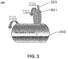
- FIG. 3 includes an illustration of a portion of a grinding system 300.
- the grinding system 300 includes an abrasive article 301 in contact with a workpiece 302 and configured to remove material from at least a portion of the surface of the workpiece 302.
- the system 300 further includes a dressing article 303 in contact with a portion of the surface of the abrasive article 301 and configured to recondition a portion of the surface of the abrasive article 301 during the process of removing material from the surface of the workpiece 302.
- the material removal operation can be conducted by moving the abrasive article relative to the workpiece.
- the abrasive article may be rotated while the workpiece is held stationary, the workpiece may be rotated while the abrasive article is held stationary, or alternatively, the abrasive article and workpiece may both be rotated relative to each other.
- the abrasive article may be traversed along a dimension of the workpiece.
- the abrasive article can be rotated in the same direction as the direction or rotation of the workpiece, or in some instances, in an opposite direction relative to each other.
- the dressing article can be rotated relative to the abrasive article and/or workpiece in a similar manner as described herein.
- the dressing article can be rotated while the workpiece and/or abrasive article are held stationary.
- the dressing article can be rotated while the abrasive article and workpiece may both be rotated relative to each other.
- the direction of rotation of the dressing article, abrasive article, and workpiece may be the same or different relative to each other.
- the process can include detecting a change in a dimension of the abrasive article.
- detecting a change in a dimension of the abrasive article can include detecting a change in any dimension of the abrasive article that may be reduced as a result of conducting the material removal process.
- the process of detecting a change in the dimension of the abrasive article can include detecting a change in the width or the diameter of the abrasive article.
- other dimensions of the abrasive article may change depending upon the orientation of the abrasive article relative to the workpiece.
- the process of detecting a change in a dimension can be conducted using a detection device, such as an optical sensor, mechanical sensor (e.g., accelerometer), mass sensor, force sensor, power sensors, acoustic sensor, and a combination thereof.
- a detection device such as an optical sensor, mechanical sensor (e.g., accelerometer), mass sensor, force sensor, power sensors, acoustic sensor, and a combination thereof.
- one or more types of sensors may be used to monitor various parameters of the grinding operation.
- the output of the accelerometers may be used to measure and/or predict resonance vibrations conditions and further facilitate altering at least one process parameter of the system in response to measured changes to avoid and/or limit resonance vibrations.
- the sensors of the system may be coupled to a computer or data system capable of receiving the input from the sensors, analyzing the input from the sensors, and even adjusting process parameters or suggesting changes to the system to a user.
- the width (w) of an abrasive article can be a dimension between two major surfaces in the case of a disk or the dimension extending in an axial direction in the case of a cone or other similar shape.
- the width of the abrasive article in FIG. 1 is labeled "w".
- the diameter "d" of the abrasive article can include the longest dimension of the abrasive article, particularly the longest dimension in the radial direction extending through a center of the abrasive article, as illustrated in FIG. 1 .
- detecting a change in dimension can include detecting a change in multiple dimensions of the body, including the width and the diameter.
- the process of detecting a change in dimension can be conducted at various times and using various methods.
- the process of detecting a change in dimension can be conducted simultaneously with the material removal process. Detecting may be completed at intervals wherein the process of removing is not occurring.
- the process of detecting a change in dimension can be conducted at regular intervals while the process of removing is occurring or at intervals when the process of removing is not occurring.
- the process of detecting a change of dimension can be conducted continuously throughout the process of removing material.
- detecting can include measuring a change in the dimension of the body of the abrasive article. Additionally, or alternatively, detecting can include calculating. Calculating may include a process wherein a rate of wear for a particular abrasive article is known, and thus the change in dimension of the body of the abrasive article may be calculated for a certain material removal operation. The foregoing processes may be conducted continuously throughout the material removal processes or alternatively, a distinct interval, which may be regular or irregular intervals as decided by an operator.
- the process can include predicting at least one resonance vibration condition.
- the method of predicting the at least one resonance vibration condition can be based on one or more process parameters, such as a change in a dimension of the abrasive article, a change in dimension of the workpiece, a change in dimension of the dressing article, a change in the profile of the abrasive article, a change in the profile of the dressing article, an operational rate of the abrasive article, an operational rate of the dressing article, an operational rate of the workpiece, a speed ratio between the abrasive article and dressing article, a speed ratio between the abrasive article and the workpiece.
- the operational rate can include a rotational rate, which can be measured in revolutions per time, or a linear rate which can be measured in length per time. It will be appreciated that the rotational rate and linear rate can be related by the dimensions of the article (i.e., workpiece, abrasive article, dressing article).
- the speed ratio can be a ratio of the operating rate of one component relative to another.
- a first speed ratio [Vw/Vaa] can describe the relationship between the operational rate of the workpiece [Vw] relative to the operational rate of the abrasive article [Vaa].
- a second speed ratio can describe a relationship between the operational rate [Vaa] of the abrasive article relative to the operational rate of the dressing article [Vda].
- reference herein to a change in a profile of the abrasive article or dressing article can refer to a change in a two-dimensional contour of the article.
- the contour can be measured along an axial plane, radial plane, and a combination thereof.
- reference to a change in profile can include a change in the roundness of the abrasive article, which is a dimension extending circumferentially about the outer perimeter of the abrasive article.
- the profile can be measured and analyzed in light of an intended profile (e.g., the original profile of the abrasive article or a preferred geometric shape). (Is this description adequate to cover the idea of sinusoidally (or otherwise) varying the wheel speed during dressing to vary the speed ratio between dresser and wheel, and thereby the forcing function on the grinding system to avoid chatter during the truing or dressing operation?)
- a resonance vibration condition may be an indicia, a numerical value, a range of values, or a range of conditions, which would likely produce a resonance vibration in the grinding system.
- the resonance vibration condition can be calculated as a value of operational rate of any or all of the components of the grinding system.
- the resonance vibration condition can be calculated as a value of a speed ratio between the abrasive article and workpiece or abrasive article and dressing article. Calculation of the resonance vibration conditions can facilitate prediction of the conditions in the grinding system most likely to cause resonance vibrations and allow a user to limit or avoid the resonance vibration condition.
- the process of predicting at least one resonance vibration condition can be in response to detecting at least one change in at least one dimension of the abrasive article and/or dressing article. Moreover, the process can include calculating at least one resonance vibration condition based on an expected change or a detected change in at least one dimension (e.g., a width, a diameter, and a combination thereof) of the abrasive article or dressing article.
- the foregoing processes may be conducted continuously throughout the material removal processes, or alternatively, a distinct interval, which may be regular or irregular intervals as decided by an operator.
- the process can further include reducing resonance vibrations of the grinding system, which can facilitate improved life of the components in the grinding system and improved results of the material removal process.
- the process of reducing resonance vibrations can be based upon detecting a change in the dimension of the abrasive article. More particularly, the process of reducing resonance vibrations can be based upon detecting a change in one or more dimensions of the abrasive article, calculating a resonance vibration condition based on the change in the one or more dimensions of the abrasive article, and reducing the resonance vibrations in the system based on the calculated resonance vibration condition.
- the process of reducing the resonance vibrations can include altering at least one of the process parameters of the grinding system, particularly any of the process parameters being measured or controlled, to facilitate avoiding and/or limiting resonance vibrations in the grinding system.
- the process can include measuring a change in diameter of the abrasive wheel during the material removal operation and altering one or a combination of speed ratios of the grinding system, based on the change in the diameter of the abrasive wheel to limit the resonance vibrations in the system.
- the process can include measuring one or more process parameters of the system and avoiding resonance vibrations in the system by continuously altering the speed of one or more components (e.g., the workpiece, the abrasive article, the dressing article). More particularly, the speed may be varied according to a known algorithm, mathematical function of the like. For example, a variation of speed over time may be described by a trigonometric function, such as a sinusoidal curve.
- a method of conducting a material removal operation using a grinding system comprises moving an abrasive article relative to a workpiece; detecting a change in a dimension of the abrasive article during moving; and reducing resonance vibrations in the grinding system.
- Item 2 relates to the method of item 1, wherein reducing resonance vibrations in the grinding system is in response to detecting the change in the dimension of the abrasive article.
- Item 3 relates to the method of item 1, wherein the grinding system comprises a dressing article, wherein the dressing article contacts the abrasive article during moving.
- Item 4 relates to the method of item 3, wherein the dressing article comprises abrasive particles contained within a bond material, wherein the abrasive particles comprise a superabrasive material.
- Item 5 relates to the method of item 3, wherein the dressing article is in contact with the abrasive article during moving.
- Item 6 relates to the method of item 1, wherein detecting the change in the dimension includes detecting a change in at least one of a width and a diameter of the abrasive article.
- Item 7 relates to the method of item 1, wherein the abrasive article comprises a bonded abrasive, wherein the bonded abrasive comprises a body including abrasive particles contained in a bond material, wherein the abrasive particles are selected from the group consisting of oxides, carbides, nitrides, borides, oxycarbides, oxynitrides, boron nitride, diamond, and a combination thereof.
- Item 8 relates to the method of item 1, wherein the abrasive article comprises abrasive particles comprising an average particle size of at least about 0.1 microns and not greater than about 5 mm.
- Item 9 relates to the method of item 1, wherein the abrasive article comprises porosity, wherein the porosity comprises closed porosity, wherein the porosity comprises open porosity, wherein the body comprises a porosity of at least about 0.1 vol% for a total volume of the body and not greater than about 70 vol%.
- Item 10 relates to the method of item 1, wherein the abrasive article comprises a body including at least about 1 vol% abrasive particle for a total volume of the body and not greater than about 60 vol%.
- Item 11 relates to the method of item 1, wherein the abrasive article comprises a body including at least about 1 vol% bond material for a total volume of the body and not greater than about 75 vol%.
- Item 12 relates to the method of item 1, wherein the abrasive article has a body comprising a shape selected from the group consisting of a cup, a wheel, an annulus, a disk having at least one tapered surface, a raised center disk, a cone, and a combination thereof.
- Item 13 relates to the method of item 1, wherein moving comprises rotating the abrasive article relative to the workpiece.
- Item 14 relates to the method of item 1, wherein the workpiece comprises an organic material.
- a method of conducting a material removal operation comprises removing material from a workpiece using an abrasive article; predicting at least one resonance vibration condition based on at least one process parameter selected from the group consisting of a change in a dimension of the abrasive article, a change in dimension of the workpiece, a change in dimension of the dressing article, an operational rate of the abrasive article, an operational rate of the dressing article, an operational rate of the workpiece, a speed ratio between the abrasive article and dressing article, a speed ratio between the abrasive article and the workpiece; and reducing resonance vibrations in response to the at least one resonance vibration condition.
- Item 16 relates to the method of item 15, wherein predicting comprises calculating the at least one resonance vibration condition based on a change in the dimension of the abrasive article.
- Item 17 relates to the method of item 15, wherein predicting is conducted simultaneously with removing.
- Item 18 relates to the method of item 15, wherein predicting comprises detecting a change in at least one dimension of the abrasive article.
- Item 19 relates to the method of item 15, wherein predicting further comprises monitoring an operating rate of the abrasive article.
- Item 20 relates to the method of item 15, wherein reducing resonance vibrations includes altering at least one process parameter.
- a method of conducting a material removal operation using a grinding system comprises removing material from a workpiece using an abrasive article; continuously monitoring a change in diameter of the abrasive article during removing material from the workpiece; and avoiding resonance vibrations in the grinding system during removing material from the workpiece.
- a method of conducting a material removal operation using a grinding system comprises removing material from a workpiece using a bonded abrasive; continuously monitoring a change in a diameter of the bonded abrasive during removing material from the workpiece; continuously predicting resonance vibration conditions in the grinding system during removing material from the workpiece; and limiting resonance vibrations in the grinding system based upon the resonance vibration conditions.
- the embodiments herein disclose a combination of process features suitable for reducing and eliminating resonance vibrations in a grinding system.
- the present methods include processes including detecting, monitoring, predicting, calculating, reducing, and a combination thereof.
- Embodiments herein are suited to detect changes in the grinding system during the material removal operation which may create new resonance conditions in the grinding system, and account for such changes and avoid the new resonance conditions.
- conventional approaches do not take into account process parameters of the system and do not predict a resonance vibration condition.
Landscapes
- Engineering & Computer Science (AREA)
- Mechanical Engineering (AREA)
- Constituent Portions Of Griding Lathes, Driving, Sensing And Control (AREA)
- Grinding-Machine Dressing And Accessory Apparatuses (AREA)
- Polishing Bodies And Polishing Tools (AREA)
Applications Claiming Priority (2)
| Application Number | Priority Date | Filing Date | Title |
|---|---|---|---|
| US201261706950P | 2012-09-28 | 2012-09-28 | |
| EP13840516.2A EP2900423B1 (fr) | 2012-09-28 | 2013-09-27 | Procédé de formation avec un article abrasif |
Related Parent Applications (1)
| Application Number | Title | Priority Date | Filing Date |
|---|---|---|---|
| EP13840516.2A Division EP2900423B1 (fr) | 2012-09-28 | 2013-09-27 | Procédé de formation avec un article abrasif |
Publications (1)
| Publication Number | Publication Date |
|---|---|
| EP3296060A1 true EP3296060A1 (fr) | 2018-03-21 |
Family
ID=50389008
Family Applications (2)
| Application Number | Title | Priority Date | Filing Date |
|---|---|---|---|
| EP17197068.4A Withdrawn EP3296060A1 (fr) | 2012-09-28 | 2013-09-27 | Article abrasif et procédé de fabrication |
| EP13840516.2A Active EP2900423B1 (fr) | 2012-09-28 | 2013-09-27 | Procédé de formation avec un article abrasif |
Family Applications After (1)
| Application Number | Title | Priority Date | Filing Date |
|---|---|---|---|
| EP13840516.2A Active EP2900423B1 (fr) | 2012-09-28 | 2013-09-27 | Procédé de formation avec un article abrasif |
Country Status (5)
| Country | Link |
|---|---|
| US (1) | US10434626B2 (fr) |
| EP (2) | EP3296060A1 (fr) |
| ES (1) | ES2657638T3 (fr) |
| PL (1) | PL2900423T3 (fr) |
| WO (1) | WO2014052822A1 (fr) |
Families Citing this family (4)
| Publication number | Priority date | Publication date | Assignee | Title |
|---|---|---|---|---|
| EP3948702A4 (fr) | 2019-03-29 | 2023-07-26 | Saint-Gobain Abrasives, Inc. | Solutions de meulage de performance |
| WO2020206382A1 (fr) | 2019-04-03 | 2020-10-08 | Saint-Gobain Abrasives, Inc. | Article abrasif, système abrasif et procédé d'utilisation et de formation de celui-ci |
| CN111604719B (zh) * | 2020-06-02 | 2021-08-10 | 湖北大学 | 一种外圆磨自适应高效率大磨削量纵磨方法 |
| US20240134341A1 (en) * | 2021-06-03 | 2024-04-25 | Saint-Gobain Abrasives, Inc. | Analytics for abrasive products and processes |
Citations (6)
| Publication number | Priority date | Publication date | Assignee | Title |
|---|---|---|---|---|
| EP0640438A1 (fr) * | 1993-08-30 | 1995-03-01 | Rikagaku Kenkyusho | Procédé et appareil pour meuler avec dressage électrolitique |
| JPH11262860A (ja) * | 1998-03-16 | 1999-09-28 | Koyo Mach Ind Co Ltd | 超精密研削方法および研削装置 |
| US6113474A (en) * | 1997-10-01 | 2000-09-05 | Cummins Engine Company, Inc. | Constant force truing and dressing apparatus and method |
| US20030194946A1 (en) * | 1998-12-16 | 2003-10-16 | University Of Massachusetts, A Massachusetts Corporation | Grinding wheel system |
| WO2005068099A1 (fr) * | 2003-12-23 | 2005-07-28 | Diamond Innovations Inc. | Meule pour application de meulage de cylindre et procede de meulage correspondant |
| US20110045739A1 (en) * | 2009-05-19 | 2011-02-24 | Saint-Gobain Abrasives, Inc. | Method and Apparatus for Roll Grinding |
Family Cites Families (10)
| Publication number | Priority date | Publication date | Assignee | Title |
|---|---|---|---|---|
| US3590799A (en) | 1968-09-03 | 1971-07-06 | Gerszon Gluchowicz | Method of dressing the grinding wheel in a grinding machine |
| US3691698A (en) * | 1970-11-23 | 1972-09-19 | Sundstrand Engelberg | Abrasive element dimension sensing mechanism |
| US4045919A (en) | 1974-05-10 | 1977-09-06 | Seiko Seiki Kabushiki Kaisha | High speed grinding spindle |
| US4295301A (en) * | 1979-11-08 | 1981-10-20 | Trw Inc. | Dressing apparatus with means for detecting grinding wheel wear |
| US5402354A (en) * | 1990-10-12 | 1995-03-28 | Mitsubishi Jukogyo Kabushiki Kaisha | Control apparatus and control method for machine tools using fuzzy reasoning |
| KR100277320B1 (ko) | 1992-06-03 | 2001-01-15 | 가나이 쓰도무 | 온라인 롤 연삭 장치를 구비한 압연기와 압연 방법 및 회전 숫돌 |
| JP2750499B2 (ja) | 1994-01-25 | 1998-05-13 | オークマ株式会社 | Nc研削盤における超砥粒砥石のドレッシング確認方法 |
| DE10104287B4 (de) * | 2001-01-30 | 2006-08-24 | Sirona Dental Systems Gmbh | Verfahren zur Bestimmung aktueller Positionsdaten eines Bearbeitungswerkzeuges und Vorrichtung hierzu |
| US7883398B2 (en) * | 2005-08-11 | 2011-02-08 | Saint-Gobain Abrasives, Inc. | Abrasive tool |
| US7797074B2 (en) * | 2007-03-01 | 2010-09-14 | Mori Seiki Usa, Inc. | Machine including grinding wheel and wheel dresser |
-
2013
- 2013-09-27 PL PL13840516T patent/PL2900423T3/pl unknown
- 2013-09-27 EP EP17197068.4A patent/EP3296060A1/fr not_active Withdrawn
- 2013-09-27 WO PCT/US2013/062288 patent/WO2014052822A1/fr not_active Ceased
- 2013-09-27 ES ES13840516.2T patent/ES2657638T3/es active Active
- 2013-09-27 EP EP13840516.2A patent/EP2900423B1/fr active Active
- 2013-09-27 US US14/431,842 patent/US10434626B2/en active Active
Patent Citations (6)
| Publication number | Priority date | Publication date | Assignee | Title |
|---|---|---|---|---|
| EP0640438A1 (fr) * | 1993-08-30 | 1995-03-01 | Rikagaku Kenkyusho | Procédé et appareil pour meuler avec dressage électrolitique |
| US6113474A (en) * | 1997-10-01 | 2000-09-05 | Cummins Engine Company, Inc. | Constant force truing and dressing apparatus and method |
| JPH11262860A (ja) * | 1998-03-16 | 1999-09-28 | Koyo Mach Ind Co Ltd | 超精密研削方法および研削装置 |
| US20030194946A1 (en) * | 1998-12-16 | 2003-10-16 | University Of Massachusetts, A Massachusetts Corporation | Grinding wheel system |
| WO2005068099A1 (fr) * | 2003-12-23 | 2005-07-28 | Diamond Innovations Inc. | Meule pour application de meulage de cylindre et procede de meulage correspondant |
| US20110045739A1 (en) * | 2009-05-19 | 2011-02-24 | Saint-Gobain Abrasives, Inc. | Method and Apparatus for Roll Grinding |
Also Published As
| Publication number | Publication date |
|---|---|
| ES2657638T3 (es) | 2018-03-06 |
| PL2900423T3 (pl) | 2018-04-30 |
| EP2900423A1 (fr) | 2015-08-05 |
| WO2014052822A1 (fr) | 2014-04-03 |
| EP2900423A4 (fr) | 2016-06-15 |
| EP2900423B1 (fr) | 2017-11-01 |
| US20150239094A1 (en) | 2015-08-27 |
| US10434626B2 (en) | 2019-10-08 |
Similar Documents
| Publication | Publication Date | Title |
|---|---|---|
| CA2809435C (fr) | Article abrasif agglomere et procede de faconnage | |
| US8029338B2 (en) | Grinding wheel for roll grinding application and method of roll grinding thereof | |
| Daneshi et al. | Effect of dressing on internal cylindrical grinding | |
| CA2793552C (fr) | Outil abrasif et procede pour finir des formes complexes dans pieces a travailler | |
| EP2900423B1 (fr) | Procédé de formation avec un article abrasif | |
| WO2012031251A2 (fr) | Articles abrasifs agglomérés, procédé de façonnage de tels articles, et efficacité de meulage de tels articles | |
| Malkin et al. | Mechanics of rotary dressing of grinding wheels | |
| CN102548714A (zh) | 具有特殊孔隙率变化的研磨工具 | |
| Badger et al. | Grinding of cermets with cup-wheels | |
| CN108698202B (zh) | 磨料工具 | |
| Prusak et al. | Influence of dressing parameters on grinding performance of CBN/Seeded Gel hybrid wheels in cylindrical grinding | |
| JP2011212782A (ja) | 砥石のドレッサの径管理方法 | |
| US20060205321A1 (en) | Super-abrasive machining tool and method of use | |
| JP2001025948A (ja) | 球体研磨砥石 | |
| JP4929790B2 (ja) | 砥石車のツルーイング方法 | |
| WO2017058769A1 (fr) | Procédé et appareil permettant d'évaluer des performances d'article abrasif lié pendant une opération de coupe par meulage | |
| WO1987001065A1 (fr) | Rodage | |
| Kodama et al. | Concentric mutual lapping to improve sliding surface function of SiC ceramics | |
| Kubo et al. | Development of solid-type diamond rotary dresser utilizing CVD diamond disc-application to low-speed dresser | |
| Buttery | Metal Finishing Processes | |
| Liang et al. | Grinding processes | |
| Suzuki et al. | GRINDING CHARACTERISTICS OF WHEELS WITH NEW cBN GRITS “ABN800” | |
| Jusko | New abrasive materials and their influence on the surface quality of bearing steel after grinding | |
| Chen et al. | Study on Spherical Face Grinding of Gcr15-Bearing-Steel Spindle Pivot by CBN Wheels | |
| VITRIFIED et al. | University of Connecticut, Storrs, CT, USA |
Legal Events
| Date | Code | Title | Description |
|---|---|---|---|
| PUAI | Public reference made under article 153(3) epc to a published international application that has entered the european phase |
Free format text: ORIGINAL CODE: 0009012 |
|
| STAA | Information on the status of an ep patent application or granted ep patent |
Free format text: STATUS: THE APPLICATION HAS BEEN PUBLISHED |
|
| AC | Divisional application: reference to earlier application |
Ref document number: 2900423 Country of ref document: EP Kind code of ref document: P |
|
| AK | Designated contracting states |
Kind code of ref document: A1 Designated state(s): AL AT BE BG CH CY CZ DE DK EE ES FI FR GB GR HR HU IE IS IT LI LT LU LV MC MK MT NL NO PL PT RO RS SE SI SK SM TR |
|
| STAA | Information on the status of an ep patent application or granted ep patent |
Free format text: STATUS: REQUEST FOR EXAMINATION WAS MADE |
|
| 17P | Request for examination filed |
Effective date: 20180905 |
|
| RBV | Designated contracting states (corrected) |
Designated state(s): AL AT BE BG CH CY CZ DE DK EE ES FI FR GB GR HR HU IE IS IT LI LT LU LV MC MK MT NL NO PL PT RO RS SE SI SK SM TR |
|
| STAA | Information on the status of an ep patent application or granted ep patent |
Free format text: STATUS: EXAMINATION IS IN PROGRESS |
|
| 17Q | First examination report despatched |
Effective date: 20210503 |
|
| GRAP | Despatch of communication of intention to grant a patent |
Free format text: ORIGINAL CODE: EPIDOSNIGR1 |
|
| STAA | Information on the status of an ep patent application or granted ep patent |
Free format text: STATUS: GRANT OF PATENT IS INTENDED |
|
| INTG | Intention to grant announced |
Effective date: 20220913 |
|
| STAA | Information on the status of an ep patent application or granted ep patent |
Free format text: STATUS: THE APPLICATION IS DEEMED TO BE WITHDRAWN |
|
| 18D | Application deemed to be withdrawn |
Effective date: 20230124 |