EP3757325B1 - Schiebetürsystem - Google Patents
Schiebetürsystem Download PDFInfo
- Publication number
- EP3757325B1 EP3757325B1 EP20182064.4A EP20182064A EP3757325B1 EP 3757325 B1 EP3757325 B1 EP 3757325B1 EP 20182064 A EP20182064 A EP 20182064A EP 3757325 B1 EP3757325 B1 EP 3757325B1
- Authority
- EP
- European Patent Office
- Prior art keywords
- latch
- bolt
- door leaf
- actuator
- sliding door
- Prior art date
- Legal status (The legal status is an assumption and is not a legal conclusion. Google has not performed a legal analysis and makes no representation as to the accuracy of the status listed.)
- Active
Links
Images

Classifications
-
- E—FIXED CONSTRUCTIONS
- E05—LOCKS; KEYS; WINDOW OR DOOR FITTINGS; SAFES
- E05D—HINGES OR SUSPENSION DEVICES FOR DOORS, WINDOWS OR WINGS
- E05D15/00—Suspension arrangements for wings
- E05D15/06—Suspension arrangements for wings for wings sliding horizontally more or less in their own plane
- E05D15/0621—Details, e.g. suspension or supporting guides
- E05D15/0626—Details, e.g. suspension or supporting guides for wings suspended at the top
-
- E—FIXED CONSTRUCTIONS
- E05—LOCKS; KEYS; WINDOW OR DOOR FITTINGS; SAFES
- E05B—LOCKS; ACCESSORIES THEREFOR; HANDCUFFS
- E05B65/00—Locks or fastenings for special use
- E05B65/08—Locks or fastenings for special use for sliding wings
- E05B65/0811—Locks or fastenings for special use for sliding wings the bolts pivoting about an axis perpendicular to the wings
- E05B65/0829—Locks or fastenings for special use for sliding wings the bolts pivoting about an axis perpendicular to the wings mounted on the slide guide, e.g. the rail
-
- E—FIXED CONSTRUCTIONS
- E05—LOCKS; KEYS; WINDOW OR DOOR FITTINGS; SAFES
- E05D—HINGES OR SUSPENSION DEVICES FOR DOORS, WINDOWS OR WINGS
- E05D15/00—Suspension arrangements for wings
- E05D15/06—Suspension arrangements for wings for wings sliding horizontally more or less in their own plane
- E05D15/0621—Details, e.g. suspension or supporting guides
- E05D15/0626—Details, e.g. suspension or supporting guides for wings suspended at the top
- E05D15/063—Details, e.g. suspension or supporting guides for wings suspended at the top on wheels with fixed axis
-
- E—FIXED CONSTRUCTIONS
- E05—LOCKS; KEYS; WINDOW OR DOOR FITTINGS; SAFES
- E05F—DEVICES FOR MOVING WINGS INTO OPEN OR CLOSED POSITION; CHECKS FOR WINGS; WING FITTINGS NOT OTHERWISE PROVIDED FOR, CONCERNED WITH THE FUNCTIONING OF THE WING
- E05F5/00—Braking devices, e.g. checks; Stops; Buffers
- E05F5/003—Braking devices, e.g. checks; Stops; Buffers for sliding wings
-
- E—FIXED CONSTRUCTIONS
- E05—LOCKS; KEYS; WINDOW OR DOOR FITTINGS; SAFES
- E05Y—INDEXING SCHEME ASSOCIATED WITH SUBCLASSES E05D AND E05F, RELATING TO CONSTRUCTION ELEMENTS, ELECTRIC CONTROL, POWER SUPPLY, POWER SIGNAL OR TRANSMISSION, USER INTERFACES, MOUNTING OR COUPLING, DETAILS, ACCESSORIES, AUXILIARY OPERATIONS NOT OTHERWISE PROVIDED FOR, APPLICATION THEREOF
- E05Y2201/00—Constructional elements; Accessories therefor
- E05Y2201/20—Brakes; Disengaging means; Holders; Stops; Valves; Accessories therefor
- E05Y2201/218—Holders
- E05Y2201/22—Locks
-
- E—FIXED CONSTRUCTIONS
- E05—LOCKS; KEYS; WINDOW OR DOOR FITTINGS; SAFES
- E05Y—INDEXING SCHEME ASSOCIATED WITH SUBCLASSES E05D AND E05F, RELATING TO CONSTRUCTION ELEMENTS, ELECTRIC CONTROL, POWER SUPPLY, POWER SIGNAL OR TRANSMISSION, USER INTERFACES, MOUNTING OR COUPLING, DETAILS, ACCESSORIES, AUXILIARY OPERATIONS NOT OTHERWISE PROVIDED FOR, APPLICATION THEREOF
- E05Y2201/00—Constructional elements; Accessories therefor
- E05Y2201/40—Motors; Magnets; Springs; Weights; Accessories therefor
- E05Y2201/404—Function thereof
- E05Y2201/41—Function thereof for closing
- E05Y2201/412—Function thereof for closing for the final closing movement
-
- E—FIXED CONSTRUCTIONS
- E05—LOCKS; KEYS; WINDOW OR DOOR FITTINGS; SAFES
- E05Y—INDEXING SCHEME ASSOCIATED WITH SUBCLASSES E05D AND E05F, RELATING TO CONSTRUCTION ELEMENTS, ELECTRIC CONTROL, POWER SUPPLY, POWER SIGNAL OR TRANSMISSION, USER INTERFACES, MOUNTING OR COUPLING, DETAILS, ACCESSORIES, AUXILIARY OPERATIONS NOT OTHERWISE PROVIDED FOR, APPLICATION THEREOF
- E05Y2900/00—Application of doors, windows, wings or fittings thereof
- E05Y2900/10—Application of doors, windows, wings or fittings thereof for buildings or parts thereof
- E05Y2900/13—Type of wing
- E05Y2900/132—Doors
Definitions
- the present invention relates to a sliding door system with at least one guide rail extending in a longitudinal direction, and a door leaf guided thereon with at least one drive, wherein the drive is fastened to an upper edge of the door leaf, and with a locking device for locking the door leaf in a closed position, wherein the locking device has a locking device with a bolt and a bolt receptacle.
- Sliding door systems especially for glass sliding doors, usually have a guide rail in which a door leaf is guided via a drive.
- the path of the drive and thus of the door leaf is limited by a limiting device.
- Such a sliding door system is made, for example, of DE 20 2007 014 567 U1 previously known.
- Sliding doors are often used to lock rooms. In order to prevent unauthorized access to a room closed with a sliding door, it is therefore necessary to lock the sliding door using a lock.
- Known solutions usually provide a lock that is arranged on one side edge of the door leaf, similar to a conventional swing door. However, such a solution is difficult to implement, particularly with glass sliding doors, or is aesthetically unfavourable because the lock is visible due to the glass door.
- the locking device consists of a lock that is attached to the guide rail and a flat arm that protrudes from the running gear in the direction of travel and acts as an engaging element for a bolt of the lock.
- the bolt of the lock can be pivoted around a horizontal axis that runs in the direction of the guide rail. This means that more space is required to pivot the bolt in a direction perpendicular to the longitudinal direction of the guide rail.
- an overhang of the guide rail laterally over the door leaf when the door leaf is closed is not desirable.
- the drive of the door leaf should also be arranged at a small distance from the side edge of the door leaf so that the door leaf can be guided with high stability and smooth running.
- a locking device of the lock forms a structural unit with a limiting device that limits the travel of the drive.
- the locking device has a bolt, with an automatic restoring force moving the bolt into an unlocking position.
- the bolt can be actuated into a locking position by an electric drive against the automatic restoring force.
- EP 2 672 041 A2 A sliding door system with a locking device for locking the door leaf is known, whereby the locking device is released by a correspondingly large force on the door leaf.
- the invention is defined by the features of claim 1.
- the sliding door system has at least one guide rail extending in a longitudinal direction and a door leaf guided thereon with at least one drive, the drive being fastened to an upper edge of the door leaf.
- a lock device is provided for locking the door leaf in a closed position, the lock device having a locking device with a bolt and a bolt receptacle, the bolt receptacle having a bolt actuator and a bolt retainer spaced apart from the bolt actuator.
- the bolt can be inserted between the bolt actuator and the bolt retainer when the door leaf is closed, the bolt actuator guiding the bolt into a retaining position against an automatic return force when the door leaf is closed.
- the bolt engages behind the bolt retainer, the locking device having a bolt retaining device which holds the bolt in the retaining position when the lock device is locked and the door leaf can be locked by actuating the bolt retaining device.
- the latch actuator moves the latch into the retaining position when the door leaf is closed, no separate drive is required for the latch, which reduces the technical effort required for the latch device.
- the latch is driven by the closing movement of the door. For example, the latch actuator can push the latch into the retaining position.
- the sliding door system according to the invention has the special feature that the bolt is guided into the retaining position each time the door leaf is closed. However, locking only occurs when the bolt holding device is actuated, which holds the bolt in the retaining position when the lock device is locked.
- This has the particular advantage that the movement of the bolt into the retaining position and the actual locking process by holding the bolt via the bolt holding device are two different processes.
- the door leaf can be opened if the bolt holding device does not hold the bolt, so that when the door leaf is opened, the bolt is returned from the retaining position to a basic position by means of the automatic return force. Without any further external influence, the latch is always in the basic position after the door leaf has been opened, so that the door leaf can then be closed without any problems.
- the latch holding device can also be designed in such a way that the latch holding device can be activated before the door leaf is closed and the latch can then be raised from the basic position into the retaining position by the latch actuator despite the holding force of the latch holding device and then held in the retaining position by the latch holding device.
- This can be possible, for example, with designs of the latch holding device in which the latch holding device holds the latch by means of a frictional connection. Designs of the latch holding device are also possible in which the latch holding device holds the latch in the retaining position by means of a positive connection.
- the bolt can thus engage in the bolt holder when the door leaf is closed and when the lock device is locked, the bolt holder holds the bolt back. It can be provided that in the retaining position the bolt is arranged between the bolt actuator and the bolt retainer.
- the automatic return force can be achieved by gravity, for example.
- a Spring device is arranged which pulls the latch towards the basic position.
- the latch actuator guides the latch from the retaining position to the basic position when the door leaf is opened in the unlocked state of the lock device, with the automatic return force pressing the latch against the latch actuator. This makes it possible to guide the latch in an advantageous manner when the door leaf is opened, since the return force means that the latch always rests against the latch actuator.
- the latch holding device is electrically actuated, whereby when the latch holding device is de-energized, it releases the latch so that the latch can then be guided into the basic position due to the independent return force when the door leaf is opened.
- the door leaf of the sliding door system according to the invention can therefore always be opened.
- the bolt has a pivot bearing and the bolt actuator guides the bolt in a pivoting movement. This allows the bolt to be guided in a particularly advantageous manner into the retaining position in which the bolt engages behind the bolt retainer.
- the pivot bearing can, for example, have a rotation axis arranged in a horizontal direction transverse to the longitudinal direction of the guide rail.
- the bolt can be pivoted in a vertical plane extending in the longitudinal direction of the guide rail.
- the bolt actuator and the bolt retainer are arranged at a distance in the vertical direction, preferably one above the other.
- the bolt it is also possible for the bolt to be arranged "lying down" so that the entire arrangement is rotated by 90°.
- the bolt can move in a horizontal plane and the bolt actuator and bolt retainer are arranged at a distance in a horizontal direction transverse to the longitudinal direction of the guide rail.
- the bolt holding device is designed as a controllable magnet and the bolt is at least partially made of a ferromagnetic material.
- the bolt holding device magnetically holds the bolt in the retaining position.
- the lock device can be operated electrically by using an electromagnet.
- the magnet attracts the bolt when actuated until the bolt rests against the magnet. This allows the bolt to be held in the retaining position in a particularly advantageous manner by means of the bolt holding device.
- the fact that the bolt rests against the magnet creates a frictional force between the magnet and the bolt, whereby the bolt can be advantageously held in the retaining position.
- the magnet attracts the bolt in a direction transverse to the plane in which the bolt can be moved from the basic position to the retaining position.
- the magnet thus attracts the bolt transverse to the pivoting plane.
- the magnet therefore acts perpendicular to the direction in which the automatic return force acts.
- the frictional force generated between the magnet and the latch thus counteracts the automatic return force.
- the latch holding device in which the latch holding device is designed as a controllable magnet, can advantageously be activated even before the door leaf is closed and the latch can be lifted from the basic position into the retaining position by the latch actuator despite the holding force of the latch holding device.
- the magnet can, for example, be a pot magnet.
- the latch has a slot, the slot being arranged opposite the magnet.
- the latch does not completely cover the contact surface of the magnet.
- the slot is narrower than the contact surface of the magnet.
- the locking device is arranged in the guide rail and the locking receptacle is arranged on the carriage or door leaf.
- the locking device is fastened in or on the guide rail and the locking receptacle is carried along with the door leaf.
- the locking receptacle can be part of the carriage or be fastened to it.
- the locking device is attached to a limiting device for limiting the path of the door leaf.
- the locking device can thus form a structural unit with the limiting device. This simplifies the assembly of the sliding door system according to the invention, since only the combination of limiting device and locking device needs to be attached to the guide rail. In addition, installation errors are avoided, since it is ensured that the locking device is in the correct position in relation to the end position of the door leaf specified by the limiting device.
- the latch actuator and the latch retainer are designed as projections, which preferably extend in horizontal direction transverse to the longitudinal direction of the guide rail. In this way, the latch actuator and the latch retainer can be provided in a structurally simple manner.
- the bolt actuator and the bolt retainer are designed symmetrically to a center plane of the bolt retainer running in the longitudinal direction of the bolt retainer. Due to the symmetrical arrangement, the bolt retainer can advantageously be used on a drive arranged on the left or right by turning the bolt retainer accordingly.
- the bolt retainer can be arranged as an additional attachment to a drive, for example.
- the bolt retainer can also be part of a carriage of the drive, for example.
- the center plane of the bolt retainer runs horizontally.
- the drive has a carriage guided in the guide rail and a fastening device connected to the carriage.
- the drive is fastened to an upper edge of the door leaf via the fastening device.
- the carriage can be fastened to the fastening device via at least one fastening means, for example via at least one screw extending in the longitudinal direction of the guide rail.
- the at least one fastening means can press the carriage and the fastening device against each other in the longitudinal direction of the guide rail, wherein at least one projection is arranged on the carriage, which extends in the longitudinal direction of the guide rail and engages in a recess of the fastening device and/or wherein at least one projection is arranged on the fastening device, which extends in the longitudinal direction of the guide rail and engages in a recess of the carriage.
- the sliding door system enables the carriage to be easily moved into a compact can be inserted into the guide rail and is then moved in the longitudinal direction of the guide rail in order to be connected to the fastening device of the door leaf.
- the at least one projection which extends in the longitudinal direction of the guide rail, engages in the corresponding recess so that the weight force can be transferred from the fastening device to the carriage via a positive connection.
- the latch receptacle has a space extending horizontally from the latch actuator and the latch retainer, into which the latch is inserted in the retaining position, wherein the space has a free space extending horizontally beyond the latch in the retaining position, which extends horizontally over a length X, wherein the length X is greater than the maximum spring travel of an elastic stop buffer for the door leaf.
- the elastic stop buffer can, for example, be part of the limiting device.
- the latch When the stop buffer is compressed when the door leaf hits, the latch can thus plunge into the free space, preventing the latch from striking the latch receptacle and thus damaging the latch.
- the space formed in the bolt holder is longer than the part of the bolt that enters the space in the retaining position, which prevents the bolt from hitting the space.
- the bolt has a first guide surface which has a contoured course, wherein the bolt actuator rests against the first guide surface when guiding the bolt.
- the first guide surface has a predetermined course with a contour.
- the contour can consist of straight and curved sections.
- the bolt actuator a second guide surface which has an arcuate profile, the second guide surface resting on the first guide surface when the bolt is guided.
- the first guide surface can, for example, have a first straight section with a first slope, a second straight section with a second slope and further curved sections.
- the bolt actuator then presses against the second section of the first guide surface.
- the shape of the first guide surface ensures that the bolt is advantageously pressed into the retention position.
- the profile of the first guide surface also ensures that it functions reliably even in embodiments of the sliding door system in which the bolt retention is arranged on the drive and can be adjusted in the vertical direction by adjusting the height of the door leaf relative to the locking device.
- the curved shape of the second guide surface which is arranged on the latch actuator, ensures that jamming between the first guide surface and the second guide surface is avoided.
- the latch retainer has a latch contact surface which is arranged on the side of the latch retainer facing away from the latch device, runs obliquely in the longitudinal direction of the latch receptacle away from the latch device and in the direction of the latch actuator, wherein the latch has a hook-shaped section which has a latch surface which runs obliquely in the same direction in the latch retaining position.
- the latch contact surface thus runs in a direction sloping away from the latch device.
- the bolt retainer can also have an inclined surface that runs diagonally in the longitudinal direction of the bolt holder away from the bolt device and towards the bolt actuator. This can ensure that in the event of a manipulative misoperation of the locking device, in which the bolt is manually pressed into the retaining position when the door leaf is open and the bolt retaining device is actuated so that the locking device is already in the locked state, the bolt is pressed towards the bolt actuator by the inclined surface of the bolt retainer when the door leaf is closed until the bolt can be inserted between the bolt retainer and the bolt actuator.
- a manipulative misoperation of the locking device in which the bolt is manually pressed into the retaining position when the door leaf is open and the bolt retaining device is actuated so that the locking device is already in the locked state, the bolt is pressed towards the bolt actuator by the inclined surface of the bolt retainer when the door leaf is closed until the bolt can be inserted between the bolt retainer and the bolt actuator.
- the carriage has rollers on one side.
- the locking receptacle can be arranged on the side of the carriage opposite the rollers. This allows a very compact design of the carriage.
- the locking receptacle is arranged together with the rollers on a carriage that can be fastened to the door leaf by means of a fastening device.
- the latch can have a bulge area adjoining the latch surface of the hook-shaped section.
- the latch retainer When the latch is held in the retaining position, the latch retainer only abuts against the latch surface when the door leaf is opened, the bulge area preventing the latch retainer from pressing the latch in the direction of the basic position.
- the door leaf can, for example, be made entirely or partially of glass.
- the door leaf is understood to be the plate-shaped part of the sliding door/door leaf.
- the drive is an attachment to the door leaf and is therefore not to be understood as part of the door leaf.
- FIG. 1 a sliding door system 1 according to the invention is shown schematically in a perspective view.
- the sliding door system 1 has a longitudinally extending guide rail 3 in which a door leaf with a Figure 1 not shown drive 4.
- the longitudinal direction is indicated by a double arrow.
- the guide rail 3 has a substantially C-shaped cross-section, with the interior of the guide rail 3 being concealed from the viewer by a cover 5.
- the guide rail 3 forms a track 7 for the running gear 4.
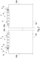
- FIG 2 the door leaf 100 with two drives 4 attached to it is shown in a schematic side view.
- the drives 4 are arranged on an upper edge 100a of the door leaf 100.
- the drive 4 consists of a carriage 9 and a fastening device 11.
- the fastening device 11 is clamped to the door leaf 100.
- the carriage 9 is attached to the fastening device 11 via fastening means not shown.
- the drives 4 are arranged in a mirror image, that is, the carriage is arranged on the side of the fastening device 11 facing the respective outer edge 100b of the door leaf 100.
- the carriages 9 can be arranged very close to the outer edge 100b, whereby a large distance can be created between the carriages 9, whereby a particularly smooth running of the door leaf 100 can be achieved.
- the carriages 9 each have two rollers 13 which are rotatably attached to a roller block 15.
- the roller block 15 is mounted on an axle 17, with the axle 17 located between the two rollers 13.
- the roller block 15 can be plate-shaped.
- the roller block can perform a rocker-like movement via the bearing of the axle 17, so that if one of the rollers 13 threatens to lift off due to an uneven surface, the other roller 13 is pressed in the direction of the track.
- the rollers 13 can roll on the track 7 of the guide rail 3.
- the design of the carriage 9 allows the door leaf 100 to be guided in the guide rail 3 with particular smoothness and ensures that both rollers 13 carry approximately the same load.
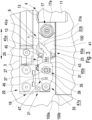
- FIG 3 a locking device 19 of the sliding door system 1 according to the invention is shown schematically in a detailed representation.
- the locking device 19 consists of a locking device 21 and a locking receiver 23.
- the locking mechanism 23 is arranged on the carriage 9 on the side opposite the rollers. As can be seen from Figure 3 As can be seen, the Axle 17 of the roller block 15 for the rollers 13 is secured on this side by means of a nut 17a.
- the locking device 21 forms a structural unit together with a limiting device 25.
- the limiting device 25 limits the travel path of the carriage 4 in the longitudinal direction of the guide rail 3.
- the longitudinal direction of the guide rail 3 is in the Figure 3 represented by a double arrow.
- the limiting device 25 has a stop buffer 27 against which the carriage 9 is pushed when the door leaf 100 is moved into its end position, which is Figure 3 shown.
- the structural unit consisting of the locking device 21 and the limiting device 25 is fastened in the guide rail 3 via a clamping device 29.
- the locking device 21 has a latch 31 which extends essentially in the longitudinal direction of the guide rail 3 and has a hook-shaped section 31a at its end.
- the bolt 31 is pivotably mounted in a vertical plane extending in the longitudinal direction of the guide rail 3.
- the bolt 31 has a pivot bearing 33 which engages the end of the bolt 31 opposite the hook-shaped section 31a.
- the pivot bearing 33 forms a rotation axis for the bolt 31 which runs in a horizontal direction transverse to the longitudinal direction of the guide rail 3.
- the bolt 31 also has a guide device 35 which consists of a guide slot 37 with a bolt inserted into the guide slot 37. The pivoting movement of the bolt 31 is guided via the guide device 35 and limited upwards and downwards.
- the bolt 31 engages in the bolt receptacle 23.
- the bolt receptacle 23 forms a space 41 in which the hook-shaped section 31a and another part of the bolt are located in the end position of the door leaf 100.
- the bolt receptacle 23 has a bolt actuator 43 and a bolt retainer 45, which are spaced apart from one another in the vertical direction. are arranged at a distance.
- the locking device 21 further comprises a locking device 47 which holds the locking device 31 in the locked state of the door leaf 100 in the Figure 3 shown retaining position.
- the bolt 31 In a state in which the bolt 31 has not yet been inserted into the bolt receptacle 23 and the bolt holding device 47 is deactivated, the bolt 31 is in a basic position in which the bolt 31 rests against the bolt 39 with the upper end of the guide slot 37 due to an automatic return force formed by gravity.
- the bolt 31 is first inserted with the hook-shaped section 31a into the opening formed between the bolt actuator 43 and the bolt retainer 45.
- the bolt actuator 43 thereby strikes a first guide surface 31b of the bolt device 21 and, as the door leaf 100 continues to move in the direction of the end position, presses the bolt 31 upwards in the direction of the Figure 3 shown retaining position.
- the latch actuator 43 has a second guide surface 43a which has an arcuate shape, whereby snagging between the latch actuator 43 and latch 31 is avoided.
- the first guide surface 31b has a partially curved profile, with a first section running diagonally at a first angle and a second section running at a second angle.
- the second guide surface 43a of the latch actuator 43 thus initially rests against the first section of the first guide surface 31b and then against the second section.
- the first guide surface 31b is designed in such a way that the latch 31 functions reliably even when the height of the door leaf is adjusted, in which the height of the drive 4 is adjusted relative to the rollers and the roller block and thus a relative adjustment between the latch holder 23 and the latch device 21 also takes place in the vertical direction.
- the latch holding device 47 is designed as a controllable magnet that forms a contact surface 47a.
- the latch 31 is made of a ferromagnetic material. When the magnet is actuated, it attracts the latch 31 in a horizontal direction transverse to the longitudinal direction of the guide rail 3, so that the latch 31 partially rests on the contact surface 47a of the magnet. This creates a frictional connection between the magnet and the latch 31, so that the latch cannot return to the home position due to the automatic return force.
- the latch holding device 47 can be activated even before the door leaf 100 is closed.
- the latch 31 is then raised by the latch actuator 43 from the basic position into the retaining position despite the holding force of the latch holding device 47 and is then held in the retaining position by the latch holding device 47.
- the activation of the latch holding device 47 before the door leaf 100 is closed has the advantage that the locking process of the door leaf 100 can be initiated regardless of its position, ensuring that the door leaf 100 is locked after the next movement into its closed position.
- the latch 31 has an elongated hole 49 opposite the magnet, so that when the magnet is actuated, only part of the contact surface 47a of the magnet rests against the latch 31. This prevents excessive residual magnetism from remaining in the latch 31 after the magnet, which can be a pot magnet, for example, is switched off, which could lead to a delay in the release of the latch 31.
- the latch actuator 43 and the latch retainer 45 are designed as projections which extend in a horizontal direction transverse to the longitudinal direction of the guide rail 3.
- the latch actuator 43 and the latch retainer 45 are opposite a longitudinal direction of the latch receptacle 23 and thus in The horizontally extending central plane of the latch holder 23 extending in the longitudinal direction of the guide rail 3 is formed symmetrically.
- the carriage 9 also has a symmetry with respect to its central plane. As a result, the carriage 9 with the latch holder 23 can also be rotated by 180° and arranged at another end of the door leaf 100 or at another door leaf.
- the space 41 has a free space 41a in the longitudinal direction of the guide rail that extends beyond the bolt 31 in the retaining position. This extends horizontally over a length X that is greater than the maximum spring travel of the elastic stop buffer 27. This ensures that even if the carriage 9 hits the elastic stop buffer 27 at high speed, where the stop buffer 27 compresses, the bolt 31 does not strike the end of the space 41.
- the bolt retainer 45 has a bolt contact surface 45a which, on the side of the bolt retainer 45 facing away from the bolt device 21, extends obliquely in the longitudinal direction of the bolt receptacle 23 away from the bolt device 21 and in the direction of the bolt actuator 43, in Figure 3 i.e., runs diagonally downwards.
- the hook-shaped section 31a has a locking surface 31c which runs diagonally in essentially the same direction in the retaining position of the bolt 31. If the door leaf 100 is moved in the direction of the opening position in the retaining position of the bolt 31 in the locked state, in which the bolt holding device holds the bolt in the retaining position, the locking surface 31c strikes the bolt contact surface 45a. Due to the diagonal course, the bolt retainer 45 is prevented from pressing the bolt 31 downwards in the direction of its basic position.
- an inclined surface 45b is arranged, which runs obliquely in the longitudinal direction of the latch receptacle 23 away from the latch device 21 and in the direction of the latch actuator 43.
- the inclined surface 45b can be parallel to the Bolt contact surface 45a.
- the locking device 19 of the sliding door system 1 has the advantage that for the locking process of the locking device 19, only the bolt holding device 47 has to be actuated, which attracts the bolt 31 and holds it in the retaining position.
- the bolt holding device therefore does not have to cause any movement of the bolt 31. Rather, the movement of the bolt 31 is caused by the movement of the door leaf 100 or the automatic return force. This keeps the technical complexity of the locking device 21 to a minimum.
Landscapes
- Engineering & Computer Science (AREA)
- Mechanical Engineering (AREA)
- Power-Operated Mechanisms For Wings (AREA)
- Lock And Its Accessories (AREA)
Description
- Die vorliegende Erfindung betrifft ein Schiebetürsystem mit mindestens einer sich in eine Längsrichtung erstreckenden Laufschiene, und einem daran mit mindestens einem Laufwerk geführten Türflügel, wobei das Laufwerk an einem oberen Rand des Türflügels befestigt ist, und mit einer Schlossvorrichtung zum Abschließen des Türflügels in einer geschlossenen Position, wobei die Schlossvorrichtung eine Riegelvorrichtung mit einem Riegel und eine Riegelaufnahme aufweist.
- Schiebetürsystem, insbesondere für Glasschiebetüren, weisen üblicherweise eine Laufschiene auf, in der ein Türflügel über ein Laufwerk geführt ist. Der Laufweg des Laufwerks und somit des Türflügels ist über eine Begrenzungsvorrichtung begrenzt. Ein derartiges Schiebetürsystem ist beispielsweise aus
DE 20 2007 014 567 U1 vorbekannt. - Schiebetüren werden häufig zum Verschließen von Räumen verwendet. Um einen unberechtigten Zugang zu einem mit einer Schiebetür verschlossenen Raum zu verhindern, besteht daher die Notwendigkeit, eine Schiebetür mittels eines Schlosses abzuschließen. Bekannte Lösungen sehen zumeist ein Schloss vor, das, ähnlich wie bei einer herkömmlichen Schwingtür, an einer Seitenkante des Türflügels angeordnet ist. Eine derartige Lösung ist jedoch insbesondere bei Glasschiebetüren nur schwierig realisierbar oder ist ästhetisch ungünstig, da aufgrund der Glastür das Schloss sichtbar ist.
- Aus
DE 10 2013 217 541 A1 der Anmelderin ist ein Schiebetürsystem mit einer Schlossvorrichtung bekannt. - Die Schlossvorrichtung besteht aus einem Schloss, das an der Laufschiene befestigt ist sowie einem an dem Laufwerk in Fahrtrichtung abstehenden flachen Arm, der als Angreifelement für einen Riegel des Schlosses wirkt. Der Riegel des Schlosses ist dabei um eine horizontale Achse, die in Richtung der Laufschiene verläuft, verschwenkbar. Dadurch wird für das Verschwenken des Riegels in einer Richtung quer zu der Längsrichtung der Laufschiene ein größerer Platzbedarf erforderlich.
- Insbesondere für Tragsysteme, die in Deckenaussparungen oder an angrenzenden Wänden angeordnet werden sollen, ist ein Überstand der Laufschiene seitlich über den Türflügel im geschlossenen Zustand des Türflügels nicht erwünscht.
- Gleichzeitig soll jedoch auch das Laufwerk des Türflügels mit geringem Abstand zu dem seitlichen Rand des Türflügels angeordnet sein, damit der Türflügel mit hoher Stabilität und Laufruhe geführt werden kann.
- Aus
DE 10 2016 217 664 B3 der Anmelderin ist daher ein Schiebetürsystem mit einem Schloss bekannt, bei dem der Bauraum in Längsrichtung der Laufschiene klein gehalten werden kann. Dabei bildet eine Riegeleinrichtung des Schlosses mit einer Begrenzungsvorrichtung, die den Laufweg des Laufwerks begrenzt, eine Baueinheit. Die Riegeleinrichtung weist einen Riegel auf, wobei eine selbsttätige Rückstellkraft den Riegel in eine Entriegelungsposition bewegt. Der Riegel ist dabei über einen elektrischen Antrieb entgegen der selbsttätigen Rückstellkraft in eine Verriegelungsposition betätigbar. Ferner ist ausEP 2 672 041 A2 ein Schiebetürsystem mit einer rastenden Feststellvorrichtung zum Feststellen des Türflügels bekannt, wobei über eine entsprechend große Kraft auf den Türflügel, die Feststellvorrichtung gelöst wird. - Bei diesem vorbekannten Schiebetürsystem ist jedoch der vorrichtungstechnische Aufwand für den elektrischen Antrieb relativ groß, insbesondere da ein möglichst geringer Bauraum verwirklicht werden soll.
- Es ist daher die Aufgabe der vorliegenden Erfindung, ein Schiebetürsystem der eingangs genannten Art zu schaffen, bei dem der Bauraum in Längsrichtung der Laufschiene klein gehalten werden kann und gleichzeitig eine einfache Konstruktion mit geringem vorrichtungstechnischen Aufwand verwirklichbar ist.
- Die Erfindung ist definiert durch die Merkmale des Anspruch 1.
- Das erfindungsgemäße Schiebetürsystem weist mindestens eine sich in eine Längsrichtung erstreckende Laufschiene und ein daran mit mindestens einem Laufwerk geführten Türflügel auf, wobei das Laufwerk an einem oberen Rand des Türflügels befestigt ist. Ferner ist eine Schlossvorrichtung zum Abschließen des Türflügels in einer geschlossenen Position vorgesehen, wobei die Schlossvorrichtung eine Riegelvorrichtung mit einem Riegel und eine Riegelaufnahme aufweist, wobei die Riegelaufnahme einen Riegelbetätiger und einen von dem Riegelbetätiger beabstandeten Riegelrückhalter aufweist. Der Riegel ist beim Schließen des Türflügels zwischen dem Riegelbetätiger und dem Riegelrückhalter einführbar, wobei der Riegelbetätiger den Riegel beim Schließen des Türflügels entgegen einer selbsttätigen Rückführkraft in eine Rückhalteposition führt. In der Rückhalteposition hintergreift der Riegel den Riegelrückhalter, wobei die Riegelvorrichtung eine Riegelhaltevorrichtung aufweist, die den Riegel im Abschließzustand der Schlossvorrichtung in der Rückhalteposition hält und wobei der Türflügel durch eine Betätigung der Riegelhaltevorrichtung abschließbar ist.
- Dadurch, dass der Riegelbetätiger den Riegel beim Schließen des Türflügels in die Rückhalteposition führt, ist kein separater Antrieb für den Riegel notwendig, wodurch der vorrichtungstechnische Aufwand für die Riegelvorrichtung reduziert ist. Der Antrieb des Riegels erfolgt über die Schließbewegung der Tür. Beispielsweise kann der Riegelbetätiger den Riegel in die Rückhalteposition drücken.
- Bei dem erfindungsgemäßen Schiebetürsystem besteht die Besonderheit, dass der Riegel bei jedem Schließvorgang des Türflügels in die Rückhalteposition geführt wird. Ein Abschließen erfolgt jedoch erst durch die Betätigung der Riegelhaltevorrichtung, die den Riegel im Abschließzustand der Schlossvorrichtung in der Rückhalteposition hält. Dies hat den besonderen Vorteil, dass die Bewegung des Riegels in die Rückhalteposition und der eigentliche Abschließvorgang durch das Halten des Riegels über die Riegelhaltevorrichtung zwei unterschiedliche Vorgänge sind. Ein Öffnen des Türflügels ist dann möglich, wenn die Riegelhaltevorrichtung den Riegel nicht hält, so dass beim Öffnen des Türflügels der Riegel mittels der selbsttätigen Rückführkraft aus der Rückhalteposition in eine Grundposition zurückgeführt wird. Ohne weiteren Einfluss von außen befindet sich somit der Riegel nach dem Öffnen des Türflügels stets in der Grundposition, sodass ein darauffolgendes Schließen des Türflügels problemlos möglich ist. Es besteht somit nicht die Gefahr, dass der Riegel im geöffneten Zustand des Türflügels sich in seiner Rückhalteposition befindet und es zu einer unbeabsichtigten Kollision zwischen der Riegelaufnahme und dem Riegel kommen kann. Bei dem erfindungsgemäßen Schiebetürsystem kann die Riegelhaltevorrichtung auch derart ausgebildet sein, dass eine Aktivierung der Riegelhaltevorrichtung bereits vor dem Schließen des Türflügels erfolgen kann und der Riegel dann trotz Haltekraft der Riegelhaltevorrichtung durch den Riegelbetätiger aus der Grundposition in die Rückhalteposition angehoben und dann durch die Riegelhaltevorrichtung in der Rückhalteposition gehalten werden kann. Dies kann beispielsweise bei Ausführungen der Riegelhaltevorrichtung, bei denen die Riegelhaltevorrichtung den Riegel mittels reibschlüssiger Verbindung hält, möglich sein. Es sind auch Ausführungen der Riegelhaltevorrichtung möglich, bei denen die Riegelhaltevorrichtung den Riegel mittels Formschluss in der Rückhalteposition hält. Auch bei derartigen Ausführungen ist es möglich, die Riegelhaltevorrichtung bereits vor dem Schließen des Türflügels zu aktivieren, wobei der Riegel bei Schließen der Tür dann in die Riegelhaltevorrichtung einschnappen kann. Die Aktivierung der Riegelhaltevorrichtung bereits vor dem Schließen des Türflügels hat den Vorteil, dass der Abschließvorgang des Türflügels unabhängig von dessen Position eingeleitet werden kann, wobei sichergestellt ist, dass nach dem nächsten Verfahren in seine geschlossene Position der Türflügel abgeschlossen ist.
- Bei dem erfindungsgemäßen Schiebetürsystem kann der Riegel somit im geschlossenen Zustand des Türflügels in die Riegelaufnahme eingreifen und im Abschließzustand der Schlossvorrichtung hält die Riegelaufnahme den Riegel zurück. Dabei kann vorgesehen sein, dass in der Rückhalteposition der Riegel zwischen Riegelbetätiger und Riegelrückhalter angeordnet ist.
- Die selbsttätige Rückführkraft kann beispielsweise über Schwerkraft erfolgen. Alternativ kann auch vorgesehen sein, dass an dem Riegel eine Federvorrichtung angeordnet ist, die den Riegel in Richtung der Grundposition zieht.
- Bei dem erfindungsgemäßen Schiebetürsystem kann vorgesehen sein, dass der Riegelbetätiger den Riegel beim Öffnen des Türflügels im aufgeschlossenen Zustand der Schlossvorrichtung aus der Rückhalteposition in die Grundposition führt, wobei die selbsttätige Rückführkraft den Riegel gegen den Riegelbetätiger drückt. Dadurch ist die Führung des Riegels beim Öffnen des Türflügels in vorteilhafter Weise möglich, da aufgrund der Rückführkraft der Riegel stets an dem Riegelbetätiger anliegt.
- Es kann vorgesehen sein, dass die Riegelhaltevorrichtung elektrisch betätigbar ist, wobei bei einem Stromlos-Schalten der Riegelhaltevorrichtung diese den Riegel freigibt, so dass dann der Riegel aufgrund der selbstständigen Rückführkraft beim Öffnen des Türflügels in die Grundposition geführt werden kann. Beispielsweise bei einem Stromausfall kann somit der Türflügel des erfindungsgemäßen Schiebetürsystems stets geöffnet werden.
- Vorzugsweise ist vorgesehen, dass der Riegel eine Drehlagerung aufweist und der Riegelbetätiger den Riegel in einer Verschwenkbewegung führt. Dadurch ist der Riegel in besonders vorteilhafter Weise in die Rückhalteposition, in der der Riegel den Riegelrückhalter hintergreift, führbar.
- Die Drehlagerung kann beispielsweise eine in horizontaler Richtung quer zu der Längsrichtung der Laufschiene angeordnete Drehachse aufweisen. Mit anderen Worten: Der Riegel kann in einer sich in Längsrichtung der Laufschiene erstreckenden vertikalen Ebene verschwenkt werden. In diesem Fall sind der Riegelbetätiger und der Riegelrückhalter in vertikaler Richtung beabstandet angeordnet, vorzugsweise übereinander angeordnet. Selbstverständlich ist auch möglich, dass der Riegel "liegend" angeordnet ist, sodass die gesamte Anordnung um 90° gedreht ist. Der Riegel kann in diesem Fall sich in einer horizontalen Ebene bewegen und Riegelbetätiger und Riegelrückhalter sind in einer horizontalen Richtung quer zur Längsrichtung der Laufschiene beabstandet angeordnet.
- Vorzugsweise ist vorgesehen, dass die Riegelhaltevorrichtung als steuerbarer Magnet ausgebildet ist und der Riegel zumindest teilweise aus einem ferromagnetischen Material besteht. Bei der Erfindung kann somit in vorteilhafter Weise vorgesehen sein, dass die Riegelhaltevorrichtung den Riegel magnetisch in der Rückhalteposition hält. Dadurch ist die Schlossvorrichtung in vorteilhafter Weise elektrisch betreibbar, indem ein Elektromagnet verwendet wird. Es kann beispielsweise vorgesehen sein, dass der Magnet bei Betätigung den Riegel anzieht, bis der Riegel an dem Magneten anliegt. Dadurch ist der Riegel in besonders vorteilhafter Weise mittels der Riegelhaltevorrichtung in der Rückhalteposition haltbar. Durch das Anliegen des Riegels an dem Magneten wird eine Reibkraft zwischen Magnet und Riegel hervorgerufen, wodurch der Riegel in vorteilhafter Weise in der Rückhalteposition gehalten werden kann. Vorzugsweise ist vorgesehen, dass der Magnet den Riegel in einer Richtung quer zu der Ebene, in der der Riegel aus der Grundposition in die Rückhalteposition bewegbar ist, anzieht. Bei einem verschwenkbaren Riegel zieht der Magnet somit den Riegel quer zu der Verschwenkebene an. Somit wirkt der Magnet quer zu der Richtung, in der die selbsttätige Rückführkraft wirkt. Die zwischen dem Magneten und dem Riegel hervorgerufene Reibkraft wirkt somit der selbsttätigen Rückführkraft entgegen. Eine derartige Anordnung hat den besonderen Vorteil, dass beim Ausschalten des Magnets der Riegel in vorteilhafter Weise freigegeben wird.
- Bei Ausführungsformen des erfindungsgemäßen Schiebetürsystems, bei denen die Riegelhaltevorrichtung als steuerbarer Magnet ausgebildet ist, kann in vorteilhafter Weise bereits eine Aktivierung der Riegelhaltevorrichtung bereits vor dem Schließen des Türflügels erfolgen und der Riegel kann trotz Haltekraft der Riegelhaltevorrichtung durch den Riegelbetätiger aus der Grundposition in die Rückhalteposition angehoben werden.
- Der Magnet kann beispielsweise ein Topfmagnet sein.
- Vorzugsweise ist vorgesehen, dass der Riegel ein Langloch aufweist, wobei das Langloch dem Magneten gegenüberliegend angeordnet ist. Mit anderen Worten: Der Riegel bedeckt nicht vollständig die Anlagefläche des Magneten. Dabei kann insbesondere vorgesehen sein, dass das Langloch schmaler ist als die Anlagefläche des Magneten.
- Durch das Vorsehen des Langlochs kann sichergestellt werden, dass ein nach dem Ausschalten des Magneten in dem Riegel verbleibender Restmagnetismus, der durch den Magneten hervorgerufen wurde, gering ist, sodass sich der Riegel sehr schnell von dem Magneten lösen kann.
- In einer bevorzugten Ausführungsform der Erfindung ist die Riegelvorrichtung in der Laufschiene angeordnet und die Riegelaufnahme an dem Laufwerk oder Türflügel angeordnet. Mit anderen Worten: Die Riegelvorrichtung ist in oder an der Laufschiene befestigt und die Riegelaufnahme wird mit dem Türflügel mitgeführt. Beispielsweise kann die Riegelaufnahme Teil des Laufwerks sein oder an diesem befestigt sein. Durch das Anordnen der Riegelvorrichtung in der Laufschiene sind die beweglichen Teile der Schlossvorrichtung und insbesondere die Riegelhaltevorrichtung stationär angeordnet und müssen nicht von dem Türflügel mitgeführt werden. Lediglich die Riegelaufnahme, die von einfachem Aufbau ist, wird von dem Türflügel mitgeführt, wodurch die Verschleißanfälligkeit des erfindungsgemäßen Schiebetürsystems gering ist.
- In einer besonders bevorzugten Ausführungsform der Erfindung ist vorgesehen, dass die Riegelvorrichtung an einer Begrenzungsvorrichtung zur Begrenzung des Laufwegs des Türflügels befestigt ist. Die Riegelvorrichtung kann somit mit der Begrenzungsvorrichtung eine Baueinheit bilden. Dadurch wird die Montage des erfindungsgemäßen Schiebetürsystems vereinfacht, da lediglich die Kombination aus Begrenzungsvorrichtung und Riegelvorrichtung in der Laufschiene befestigt werden muss. Darüber hinaus werden Einbaufehler vermieden, da sichergestellt ist, dass sich der Riegel in Bezug auf die durch die Begrenzungsvorrichtung vorgegebene Endposition des Türflügels in der richtigen Position befindet.
- Vorzugsweise ist vorgesehen, dass der Riegelbetätiger und der Riegelrückhalter als Vorsprünge ausgebildet sind, die sich vorzugsweise in horizontaler Richtung quer zu der Längsrichtung der Laufschiene erstrecken. Auf diese Weise sind der Riegelbetätiger und der Riegelrückhalter auf konstruktiv einfache Weise bereitstellbar.
- Vorzugsweise ist vorgesehen, dass der Riegelbetätiger und der Riegelrückhalter symmetrisch zu einer Längsrichtung der Riegelaufnahme verlaufenden Mittelebene der Riegelaufnahme ausgebildet sind. Durch die symmetrische Anordnung kann die Riegelaufnahme in vorteilhafter Weise an einem linksseitig oder rechtsseitig angeordneten Laufwerk verwendet werden, indem die Riegelaufnahme entsprechend umgedreht wird. Die Riegelaufnahme kann beispielsweise als zusätzliches Anbauteil an einem Laufwerk angeordnet werden. Auch kann die Riegelaufnahme beispielsweise Teil eines Laufwagens des Laufwerks sein. Bei einer Ausführungsform der Schlossvorrichtung, bei der der Riegel in einer vertikalen Ebene bewegt wird und sich Riegelbetätiger und Riegelrückhalter in vertikaler Richtung übereinander befinden, verläuft die Mittelebene der Riegelaufnahme horizontal.
- Vorzugsweise ist vorgesehen, dass das Laufwerk einen in der Laufschiene geführten Laufwagen und eine mit dem Laufwagen verbundene Befestigungsvorrichtung aufweist. Über die Befestigungsvorrichtung ist das Laufwerk an einem oberen Rand des Türflügels befestigt. Der Laufwagen kann über mindestens ein Befestigungsmittel an der Befestigungsvorrichtung befestigt sein, beispielsweise über mindestens eine sich in Längsrichtung der Laufschiene erstreckende Schraube. Das mindestens eine Befestigungsmittel kann den Laufwagen und die Befestigungsvorrichtung in Längsrichtung der Laufschiene gegeneinander drücken, wobei an dem Laufwagen mindestens ein Vorsprung angeordnet ist, der sich in Längsrichtung der Laufschiene erstreckt und in eine Aussparung der Befestigungsvorrichtung eingreift und/oder wobei an der Befestigungsvorrichtung mindestens ein Vorsprung angeordnet ist, der sich in Längsrichtung der Laufschiene erstreckt und in eine Aussparung des Laufwagens eingreift.
- Das erfindungsgemäße Schiebetürsystem ermöglicht auf einfache Art und Weise, dass der Laufwagen zunächst in eine kompakt ausgestaltete Laufschiene eingesetzt werden kann und anschließend in Längsrichtung der Laufschiene verschoben wird, um mit der Befestigungsvorrichtung des Türflügels verbunden zu werden. Dabei greift der mindestens eine Vorsprung, der sich in Längsrichtung der Laufschiene erstreckt, in die entsprechende Aussparung ein, sodass eine Übertragung der Gewichtskraft von der Befestigungsvorrichtung auf den Laufwagen über einen Formschluss erfolgen kann.
- In einem bevorzugten Ausführungsbeispiel des erfindungsgemäßen Schiebetürsystems ist vorgesehen, dass die Riegelaufnahme einen sich von dem Riegelbetätiger und dem Riegelrückhalter in horizontaler Richtung erstreckenden Raum aufweist, in den der Riegel in der Rückhalteposition eingeführt ist, wobei der Raum in horizontaler Richtung einen sich über den Riegel in der Rückhalteposition hinaus erstreckenden Freiraum aufweist, der sich in horizontaler Richtung über eine Länge X erstreckt, wobei die Länge X größer als der maximale Federweg eines elastischen Anschlagpuffers für den Türflügel ist. Der elastische Anschlagpuffer kann beispielsweise Teil der Begrenzungsvorrichtung sein. Die Erfindung sieht somit vor, dass die Riegelaufnahme nicht nur einen sich in horizontaler Richtung erstreckenden Raum aufweist, in den der Riegel in der Rückhalteposition eingeführt ist, sondern darüber hinaus dieser Raum noch einen Freiraum bildet. Bei einem Einfedern des Anschlagpuffers bei einem Auftreffen des Türflügels kann somit der Riegel in den Freiraum eintauchen, sodass ein Anschlagen des Riegels in der Riegelaufnahme und somit eine Beschädigung des Riegels verhindert wird. Mit anderen Worten: Der in der Riegelaufnahme gebildete Raum ist länger als der in der Rückhaltposition in den Raum eintauchende Teil des Riegels, wodurch ein Anschlagen des Riegels in dem Raum verhindert wird.
- Vorzugsweise ist vorgesehen, dass der Riegel eine erste Führungsfläche aufweist, die einen konturierten Verlauf aufweist, wobei der Riegelbetätiger beim Führen des Riegels an der ersten Führungsfläche anliegt. Mit anderen Worten, die erste Führungsfläche weist einen vorgegebenen Verlauf mit einer Kontur auf. Beispielsweise kann die Kontur aus geraden und gekrümmten Abschnitten bestehen. Ferner kann vorgesehen sein, dass der Riegelbetätiger eine zweite Führungsfläche aufweist, die einen bogenförmigen Verlauf aufweist, wobei die zweite Führungsfläche beim Führen des Riegels an der ersten Führungsfläche anliegt. Die erste Führungsfläche kann beispielsweise einen ersten geraden Abschnitt mit einer ersten Steigung, einen zweiten geraden Abschnitt mit einer zweiten Steigung sowie weitere gekrümmte Abschnitte aufweisen. Bei einem Einführen des Riegels in die Riegelaufnahme liegt der Riegelbetätiger zunächst an dem ersten Abschnitt an und drückt den Riegel in Richtung der Riegelrückhalteposition. Anschließend drückt der Riegelbetätiger gegen den zweiten Abschnitt der ersten Führungsfläche. Die Form der ersten Führungsfläche gewährleistet, dass der Riegel in vorteilhafter Weise in die Rückhalteposition gedrückt wird. Durch den Verlauf der ersten Führungsfläche wird darüber hinaus sichergestellt, dass auch bei Ausführungsformen des Schiebetürsystems, bei denen die Riegelaufnahme an dem Laufwerk angeordnet ist und durch eine Höhenverstellung des Türflügels gegenüber der Riegelvorrichtung in vertikaler Richtung verstellbar ist, in zuverlässiger Weise funktioniert. Der bogenförmige Verlauf der zweiten Führungsfläche, die an dem Riegelbetätiger angeordnet ist, sorgt dafür, dass ein Verkanten zwischen der ersten Führungsfläche und der zweiten Führungsfläche vermieden wird.
- Vorzugsweise ist vorgesehen, dass der Riegelrückhalter eine Riegelanlagefläche aufweist, die an der von der Riegelvorrichtung abgewandten Seite des Riegelrückhalters angeordnet ist, schräg in Längsrichtung der Riegelaufnahme von der Riegelvorrichtung weg und in Richtung zu dem Riegelbetätiger hin verläuft, wobei der Riegel einen hakenförmigen Abschnitt aufweist, der einen in der Rückhalteposition des Riegels in gleiche Richtung schräg verlaufende Riegelfläche aufweist. Bei einem Riegel, der in einer vertikalen Ebene bewegbar ist, sodass sich der Riegelbetätiger und der Riegelrückhalter übereinander befinden, verläuft die Riegelanlagefläche somit in einer Richtung von der Riegelvorrichtung weg abfallend. Durch die in gleicher Richtung schräg verlaufende Riegelfläche wird somit in vorteilhafter Weise ein Hintergreifen ermöglicht, sodass bei einem Aufziehen des Türflügels mit in der Rückhalteposition gehaltenem Riegel verhindert wird, dass der Riegelrückhalter den Riegel in Richtung der Grundposition drückt.
- Auf der der Riegelvorrichtung zugewandten Seite kann der Riegelrückhalter ebenfalls eine Schrägfläche aufweisen, die schräg in Längsrichtung der Riegelaufnahme von der Riegelvorrichtung weg und in Richtung zu dem Riegelbetätiger hin verläuft. Dadurch kann sichergestellt werden, dass bei einer manipulativen Fehlbetätigung der Schlossvorrichtung, bei der im geöffneten Zustand des Türflügels der Riegel manuell in die Rückhalteposition gedrückt wird und die Riegelhaltevorrichtung betätigt wird, so dass sich die Schlossvorrichtung bereits im Abschließzustand befindet, der Riegel beim Schließen des Türflügels von der Schrägfläche des Riegelrückhalters in Richtung zu dem Riegelbetätiger gedrückt wird, bis der Riegel zwischen Riegelrückhalter und Riegelbetätiger eingeführt werden kann. Eine derartige Funktion ist jedoch nur bei Ausführungen der Schlossvorrichtung möglich, bei denen die Riegelhaltevorrichtung den Riegel mittels reibschlüssiger Verbindung hält, wobei der Riegel entgegen der Haltekraft bewegt wird.
- Bei dem erfindungsgemäßen Schiebetürsystem kann auch vorgesehen sein, dass das Laufwerk einseitig Laufrollen aufweist. Dabei kann die Riegelaufnahme auf der den Laufrollen gegenüberliegenden Seite des Laufwerks angeordnet sein. Dadurch ist ein sehr kompakter Aufbau des Laufwerks möglich. Insbesondere kann vorgesehen sein, dass die Riegelaufnahme zusammen mit den Laufrollen an einem Laufwagen, der mittels einer Befestigungsvorrichtung an dem Türflügel befestigbar ist, angeordnet ist.
- Der Riegel kann einen an die Riegelfläche des hakenförmigen Abschnitts anschließenden Ausbuchtungsbereich aufweisen. Bei einem in der Rückhalteposition gehaltenen Riegel stößt somit beim Öffnen des Türflügels der Riegelrückhalter ausschließlich gegen die Riegelfläche, wobei der Ausbuchtungsbereich verhindert, dass der Riegelrückhalter den Riegel in Richtung der Grundposition drücken kann.
- Der Türflügel kann beispielsweise ganz oder teilweise aus Glas bestehen. Im Rahmen der Erfindung wird unter dem Türflügel der plattenförmige Teil der Schiebetür/das Türblatt verstanden. Das Laufwerk ist ein Anbauteil an dem Türflügel und somit nicht als Teil des Türflügels zu verstehen.
- Im Folgenden wird unter Bezugnahme auf die nachfolgenden Figuren die Erfindung näher erläutert. Es zeigen
- Fig. 1
- eine schematische perspektivische Darstellung des erfindungsgemäßen Schiebetürsystems,
- Fig. 2
- eine schematische Draufsicht auf den Türflügel mit an dem Türflügel befestigten Laufwerken und
- Fig. 3
- eine schematische Detaildarstellung der Schlossvorrichtung des erfindungsgemäßen Schiebetürsystems.
- In
Figur 1 ist ein erfindungsgemäßes Schiebetürsystem 1 schematisch in einer perspektivischen Darstellung gezeigt. - Das erfindungsgemäße Schiebetürsystem 1 weist eine sich in Längsrichtung erstreckende Laufschiene 3 auf, in der ein Türflügel mit einem in
Figur 1 nicht dargestellten Laufwerk 4 geführt ist. Die Längsrichtung ist durch einen Doppelpfeil verdeutlicht. Die Laufschiene 3 weist einen im Wesentlichen C-förmigen Querschnitt auf, wobei über eine Blende 5 das Innere der Laufschiene 3 für den Betrachter verdeckt ist. - Die Laufschiene 3 bildet eine Laufbahn 7 für das Laufwerk 4.
- In
Figur 2 ist der Türflügel 100 mit zwei daran befestigten Laufwerken 4 in einer schematischen Seitenansicht gezeigt. Die Laufwerke 4 sind an einem oberen Rand 100a des Türflügels 100 angeordnet. - Das Laufwerk 4 besteht aus einem Laufwagen 9 und einer Befestigungsvorrichtung 11. Die Befestigungsvorrichtung 11 ist klemmend an dem Türflügel 100 befestigt. Der Laufwagen 9 ist über nicht dargestellte Befestigungsmittel an der Befestigungsvorrichtung 11 befestigt.
- Wie aus
Figur 2 ersichtlich ist, sind die Laufwerke 4 spiegelbildlich angeordnet, das heißt, der Laufwagen ist jeweils auf der zum jeweiligen äußeren Rand 100b des Türflügels 100 zugewandten Seite der Befestigungsvorrichtung 11 angeordnet. Dadurch können die Laufwagen 9 sehr nah am äußeren Rand 100b angeordnet werden, wodurch zwischen den Laufwagen 9 ein großer Abstand geschaffen werden kann, wodurch eine besondere Laufruhe des Türflügels 100 erreicht werden kann. - Die Laufwagen 9 weisen jeweils zwei Laufrollen 13 auf, die an einem Rollenbock 15 drehbar befestigt sind. Der Rollenbock 15 ist über eine Achse 17 gelagert, wobei die Achse 17 sich zwischen den beiden Laufrollen 13 befindet. Insbesondere kann der Rollenbock 15 plattenförmig ausgebildet sein. Über die Lagerung der Achse 17 kann der Rollenbock eine wippenartige Bewegung ausführen, sodass, wenn eine der Laufrollen 13 durch eine Unebenheit abzuheben droht, die andere Laufrolle 13 in Richtung der Laufbahn gedrückt wird. Die Laufrollen 13 können auf der Laufbahn 7 der Laufschiene 3 abrollen. Durch die Ausgestaltung des Laufwagens 9 kann der Türflügel 100 mit besonderer Laufruhe in der Laufschiene 3 geführt werden und es sichergestellt ist, dass beide Laufrollen 13 annähernd die gleiche Last tragen.
- In
Figur 3 ist eine Schlossvorrichtung 19 des erfindungsgemäßen Schiebetürsystems 1 schematisch in einer Detaildarstellung dargestellt. - Die Schlossvorrichtung 19 besteht aus einer Riegelvorrichtung 21 und einer Riegelaufnahme 23.
- Die Riegelaufnahme 23 ist an dem Laufwagen 9 an der den Laufrollen gegenüberliegenden Seite angeordnet. Wie aus
Figur 3 ersichtlich ist, ist die Achse 17 des Rollenbocks 15 für die Laufrollen 13 an dieser Seite mittels einer Mutter 17a gesichert. - Die Riegelvorrichtung 21 bildet zusammen mit einer Begrenzungsvorrichtung 25 eine Baueinheit. Die Begrenzungsvorrichtung 25 begrenzt den Laufweg des Laufwerks 4 in Längsrichtung der Laufschiene 3. Die Längsrichtung der Laufschiene 3 ist in der
Figur 3 durch einen Doppelpfeil dargestellt. Die Begrenzungsvorrichtung 25 weist einen Anschlagpuffer 27 auf, gegen den der Laufwagen 9 beim Verfahren des Türflügels 100 in seine Endstellung, die inFigur 3 dargestellt ist, anstößt. - Die aus der Riegelvorrichtung 21 und der Begrenzungsvorrichtung 25 bestehende Baueinheit ist über eine Klemmvorrichtung 29 in der Laufschiene 3 befestigt. Die Riegelvorrichtung 21 weist einen Riegel 31 auf, der sich im Wesentlichen in Längsrichtung der Laufschiene 3 erstreckt und an seinem Ende einen hakenförmigen Abschnitt 31a aufweist.
- Der Riegel 31 ist in einer sich in Längsrichtung der Laufschiene 3 erstreckenden vertikalen Ebene verschwenkbar gelagert. Dazu weist der Riegel 31 eine Drehlagerung 33 auf, die an dem dem hakenförmigen Abschnitt 31a gegenüberliegenden Ende des Riegels 31 angreift. Die Drehlagerung 33 bildet eine sich in horizontaler Richtung quer zu der Längsrichtung der Laufschiene 3 verlaufende Drehachse für den Riegel 31. Ferner weist der Riegel 31 eine Führungseinrichtung 35 auf, die aus einem Führungslangloch 37 mit in das Führungslangloch 37 eingestecktem Bolzen besteht. Über die Führungseinrichtung 35 wird die Verschwenkbewegung des Riegels 31 geführt und nach oben und nach unten hin begrenzt.
- Wie aus
Figur 3 ersichtlich ist, greift der Riegel 31 in die Riegelaufnahme 23 ein. Hierzu bildet die Riegelaufnahme 23 einen Raum 41, in dem sich in der Endposition des Türflügels 100 der hakenförmige Abschnitt 31a sowie ein weiterer Teil des Riegels befinden. An dem zu der Riegelvorrichtung 21 gewandten Ende weist die Riegelaufnahme 23 einen Riegelbetätiger 43 und einen Riegelrückhalter 45 auf, die in vertikaler Richtung voneinander beabstandet angeordnet sind. Die Riegelvorrichtung 21 weist ferner eine Riegelhaltevorrichtung 47 auf, die den Riegel 31 im Abschließzustand des Türflügels 100 in der inFigur 3 dargestellten Rückhalteposition hält. - In einem Zustand, in dem der Riegel 31 noch nicht in die Riegelaufnahme 23 eingeführt und die Riegelhaltevorrichtung 47 deaktiviert ist, befindet sich der Riegel 31 in einer Grundposition, in der der Riegel 31 aufgrund einer durch die Schwerkraft gebildeten selbsttätigen Rückführkraft mit dem oberen Ende des Führungslanglochs 37 an dem Bolzen 39 anliegt. Bei der Schließbewegung des Türflügels 100 wird der Riegel 31 zunächst mit dem hakenförmigen Abschnitt 31a in die zwischen dem Riegelbetätiger 43 und dem Riegelrückhalter 45 gebildeten Öffnung eingeführt. Der Riegelbetätiger 43 stößt dabei gegen eine erste Führungsfläche 31b der Riegelvorrichtung 21 und drückt bei der weiteren Bewegung des Türflügels 100 in Richtung der Endstellung den Riegel 31 entgegen der selbsttätigen Rückführkraft und unabhängig davon, ob die Riegelhaltevorrichtung 47 aktiviert oder deaktiviert ist, nach oben in Richtung der in
Figur 3 dargestellten Rückhalteposition. Der Riegelbetätiger 43 weist hierzu eine zweite Führungsfläche 43a auf, die einen bogenförmigen Verlauf aufweist, wodurch ein Verhaken zwischen Riegelbetätiger 43 und Riegel 31 vermieden wird. - Die erste Führungsfläche 31b weist einen teilweise gekrümmten Verlauf auf, mit einem schräg in einem ersten Winkel verlaufenden ersten Abschnitt und einem daran anschließenden in einem zweiten Winkel verlaufenden zweiten Abschnitt. Die zweite Führungsfläche 43a des Riegelbetätigers 43 liegt somit zunächst an dem ersten Abschnitt der ersten Führungsfläche 31b und anschließend an dem zweiten Abschnitt an. Die erste Führungsfläche 31b ist so ausgestaltet, dass der Riegel 31 auch bei einer Höhenverstellung des Türflügels, bei dem das Laufwerk 4 gegenüber den Rollen und dem Rollenbock in der Höhe verstellt wird und somit auch eine relative Verstellung zwischen der Riegelaufnahme 23 und der Riegelvorrichtung 21 in vertikaler Richtung erfolgt, zuverlässig funktioniert.
- Die Riegelhaltevorrichtung 47 ist als steuerbarer Magnet ausgebildet, der eine Anlagefläche 47a bildet. Der Riegel 31 ist aus einem ferromagnetischen Material gefertigt. Bei der Betätigung des Magneten zieht dieser den Riegel 31 in horizontaler Richtung quer zur Längsrichtung der Laufschiene 3 an, sodass der Riegel 31 teilweise an der Anlagefläche 47a des Magneten anliegt. Dadurch wird zwischen dem Magneten und dem Riegel 31 eine reibschlüssige Verbindung gebildet, sodass der Riegel nicht durch die selbsttätige Rückführkraft in die Grundposition zurückkehren kann.
- Bei dem erfindungsgemäßen Schiebetürsystem 1 kann eine Aktivierung der Riegelhaltevorrichtung 47 bereits vor dem Schließen des Türflügels 100 erfolgen. Der Riegel 31 wird dann beim Schließen des Türflügels 100 trotz Haltekraft der Riegelhaltevorrichtung 47 durch den Riegelbetätiger 43 aus der Grundposition in die Rückhalteposition angehoben und dann durch die Riegelhaltevorrichtung 47 in der Rückhalteposition gehalten.
- Die Aktivierung der Riegelhaltevorrichtung 47 bereits vor dem Schließen des Türflügels 100 hat den Vorteil, dass der Abschließvorgang des Türflügels 100 unabhängig von dessen Position eingeleitet werden kann, wobei sichergestellt ist, dass nach dem nächsten Verfahren in seine geschlossene Position der Türflügel 100 abgeschlossen ist.
- Der Riegel 31 weist dem Magneten gegenüberliegend ein Langloch 49 auf, sodass bei der Betätigung des Magneten nur ein Teil der Anlagefläche 47a des Magneten an dem Riegel 31 anliegt. Dadurch wird verhindert, dass nach dem Ausschalten des Magneten, der beispielsweise ein Topfmagnet sein kann, ein zu großer Restmagnetismus in dem Riegel 31 verbleibt, was zu einer Verzögerung des Lösens des Riegels 31 führen könnte.
- Der Riegelbetätiger 43 und der Riegelrückhalter 45 sind als Vorsprünge ausgebildet, die sich in horizontaler Richtung quer zur Längsrichtung der Laufschiene 3 erstrecken. Der Riegelbetätiger 43 und der Riegelrückhalter 45 sind gegenüber einer in Längsrichtung der Riegelaufnahme 23 und somit in Längsrichtung der Laufschiene 3 erstreckenden horizontal verlaufenden Mittelebene der Riegelaufnahme 23 symmetrisch ausgebildet.
- Auch der Laufwagen 9 weist eine Symmetrie zu seiner Mittelebene auf. Dadurch kann der Laufwagen 9 mit der Riegelaufnahme 23 auch um 180° gedreht an einem anderen Ende des Türflügels 100 oder an einem anderen Türflügel angeordnet werden.
- Der Raum 41 weist in Längsrichtung der Laufschiene einen sich über den Riegel 31 in der Rückhalteposition hinaus erstreckenden Freiraum 41a auf. Dieser erstreckt sich in horizontaler Richtung über eine Länge X, die größer ist als der maximale Federweg des elastischen Anschlagpuffers 27. Dadurch wird sichergestellt, dass auch bei einem Anstoßen des Laufwagens 9 mit hoher Geschwindigkeit an den elastischen Anschlagpuffer 27, bei dem der Anschlagpuffer 27 einfedert, der Riegel 31 nicht gegen das Ende des Raumes 41 anschlägt.
- Der Riegelrückhalter 45 weist eine Riegelanlagefläche 45a auf, die auf der von der Riegelvorrichtung 21 abgewandten Seite des Riegelrückhalters 45 schräg in Längsrichtung der Riegelaufnahme 23 von der Riegelvorrichtung 21 weg und in Richtung zu dem Riegelbetätiger 43 hin, in
Figur 3 also nach schräg unten, verläuft. Der hakenförmige Abschnitt 31a weist eine Riegelfläche 31c auf, die in der Rückhalteposition des Riegels 31 im Wesentlichen in gleicher Richtung schräg verläuft. Wird in der Rückhalteposition des Riegels 31 im Abschließzustand, in der die Riegelhaltevorrichtung den Riegel in der Rückhalteposition hält, der Türflügel 100 in Richtung der Öffnungsposition bewegt, stößt die Riegelfläche 31c gegen die Riegelanlagefläche 45a. Aufgrund des schrägen Verlaufs wird verhindert, dass der Riegelrückhalter 45 den Riegel 31 nach unten in Richtung seiner Grundposition drückt. - Auf der der Riegelvorrichtung 21 zugewandten Seite des Riegelrückhalters 45 ist eine Schrägfläche 45b angeordnet, die schräg in Längsrichtung der Riegelaufnahme 23 von der Riegelvorrichtung 21 weg und in Richtung zu dem Riegelbetätiger 43 hin verläuft. Die Schrägfläche 45b kann parallel zu der Riegelanlagefläche 45a verlaufen. Dadurch kann sichergestellt werden, dass bei einer manipulativen Fehlbetätigung der Schlossvorrichtung 19, bei der im geöffneten Zustand des Türflügels 100 der Riegel 31 manuell in die Rückhalteposition gedrückt wird und die Riegelhaltevorrichtung 47 betätigt wird, so dass sich die Schlossvorrichtung 19 bereits im Abschließzustand befindet, der Riegel 31 beim Schließen des Türflügels 100 von der Schrägfläche 45b des Riegelrückhalters 45 in Richtung zu dem Riegelbetätiger 43 gedrückt wird, bis der Riegel 31 zwischen Riegelrückhalter 45 und Riegelbetätiger 43 eingeführt werden kann.
- Die Schlossvorrichtung 19 des erfindungsgemäßen Schiebetürsystems 1 hat den Vorteil, dass für den Abschließvorgang der Schlossvorrichtung 19 lediglich die Riegelhaltevorrichtung 47 betätigt werden muss, die den Riegel 31 anzieht und in der Rückhalteposition hält. Die Riegelhaltevorrichtung muss somit keine Bewegung des Riegels 31 hervorrufen. Vielmehr wird die Bewegung des Riegels 31 durch die Bewegung des Türflügels 100 bzw. die selbsttätige Rückführkraft hervorgerufen. Dadurch ist der vorrichtungstechnische Aufwand der Riegelvorrichtung 21 geringgehalten.
-
- 1
- Schiebetürsystem
- 3
- Laufschiene
- 4
- Laufwerk
- 5
- Blende
- 7
- Laufbahn
- 9
- Laufwagen
- 11
- Befestigungsvorrichtung
- 13
- Laufrollen
- 15
- Rollenbock
- 17
- Achse
- 17a
- Mutter
- 19
- Schlossvorrichtung
- 21
- Riegelvorrichtung
- 23
- Riegelaufnahme
- 25
- Begrenzungsvorrichtung
- 27
- elastischer Anschlagpuffer
- 29
- Klemmvorrichtung
- 31
- Riegel
- 31a
- hakenförmiger Abschnitt
- 31b
- erste Führungsfläche
- 31c
- Riegelfläche
- 33
- Drehlagerung
- 35
- Führungseinrichtung
- 37
- Führungslangloch
- 39
- Bolzen
- 41
- Raum
- 41a
- Freiraum
- 43
- Riegelbetätiger
- 43a
- zweite Führungsfläche
- 45
- Riegelrückhalter
- 45a
- Riegelanlagefläche
- 45b
- Schrägfläche
- 47
- Riegelhaltevorrichtung
- 47a
- Anlagefläche
- 49
- Langloch
- 100
- Türflügel
- 100a
- oberer Rand
- 100b
- äußerer Rand
Claims (13)
- Schiebetürsystem (1) mit mindestens einer sich in eine Längsrichtung erstreckenden Laufschiene (3), und einem daran mit mindestens einem Laufwerk (4) geführten Türflügel (100), wobei das Laufwerk (4) an einem oberen Rand (100a) des Türflügels (100) befestigt ist, und mit einer Schlossvorrichtung (19) zum Abschließen des Türflügels (100) in einer geschlossenen Position, wobei die Schlossvorrichtung (19) eine Riegelvorrichtung (21) mit einem Riegel (31) aufweist,wobei die Schlossvorrichtung (19) eine Riegelaufnahme (23) aufweist, wobei die Riegelaufnahme (23) einen Riegelbetätiger (43) und einen von dem Riegelbetätiger (43) beabstandeten Riegelrückhalter (45) aufweist, wobei der Riegel (31) beim Schließen des Türflügels (100) zwischen dem Riegelbetätiger (43) und dem Riegelrückhalter (45) einführbar istdadurch gekennzeichnet, dassder Riegelbetätiger (43) den Riegel (31) beim Schließen des Türflügels (100) entgegen einer selbsttätigen Rückführkraft in eine Rückhalteposition führt, wobei der Riegel (31) in der Rückhalteposition den Riegelrückhalter (45) hintergreift, wobei die Riegelvorrichtung (21) eine Riegelhaltevorrichtung (47) aufweist, die den Riegel (31) im Abschließzustand der Schlossvorrichtung (19) in der Rückhalteposition hält und wobei der Türflügel (100) durch eine Betätigung der Riegelhaltevorrichtung (47) abschließbar ist.
- Schiebetürsystem nach Anspruch 1, dadurch gekennzeichnet, dass der Riegelbetätiger (43) den Riegel (31) beim Öffnen des Türflügels (100) im aufgeschlossenen Zustand der Schlossvorrichtung (19) aus der Rückhalteposition in eine Grundposition führt, wobei die Rückführkraft den Riegel (31) gegen den Riegelbetätiger (43) drückt.
- Schiebetürsystem nach Anspruch 1 oder 2, dadurch gekennzeichnet, dass der Riegel (31) eine Drehlagerung aufweist und der Riegelbetätiger (43) den Riegel (31) in einer Verschwenkbewegung führt.
- Schiebetürsystem nach einem der Ansprüche 1 bis 3, dadurch gekennzeichnet, dass die Riegelhaltevorrichtung (47) als steuerbarbarer Magnet ausgebildet ist und der Riegel (31) zumindest teilweise aus einem ferromagnetischen Material besteht.
- Schiebetürsystem nach Anspruch 4, dadurch gekennzeichnet, dass der Riegel (31) ein Langloch (49) aufweist, wobei das Langloch dem Magneten gegenüberliegend angeordnet ist.
- Schiebetürsystem nach einem der Ansprüche 1 bis 5, dadurch gekennzeichnet, dass die Riegelvorrichtung (21) in der Laufschiene angeordnet ist und die Riegelaufnahme (23) an dem Laufwerk (4) oder Türflügel (100) angeordnet ist.
- Schiebetürsystem nach Anspruch 6, dadurch gekennzeichnet, dass die Riegelvorrichtung (21) an einer Begrenzungsvorrichtung (25) zur Begrenzung des Laufwegs des Türflügels (100) befestigt ist.
- Schiebetürsystem nach einem der Ansprüche 1 bis 7, dadurch gekennzeichnet, dass der Riegelbetätiger (43) und der Riegelrückhalter (45) als Vorsprünge ausgebildet sind, die sich vorzugsweise in horizontaler Richtung quer zu der Längsrichtung der Laufschiene erstrecken.
- Schiebetürsystem nach einem der Ansprüche 1 bis 8, dadurch gekennzeichnet, dass der Riegelbetätiger (43) und der Riegelrückhalter (45) symmetrisch zu einer in Längsrichtung der Riegelaufnahme (23) verlaufenden Mittelebene der Riegelaufnahme (23) ausgebildet sind.
- Schiebetürsystem nach einem der Ansprüche 1 bis 9, dadurch gekennzeichnet, dass die Riegelaufnahme (23) einen sich von dem Riegelbetätiger (43) und dem Riegelrückhalter (45) in horizontaler Richtung erstreckenden Raum aufweist, in den der Riegel (31) in der Rückhalteposition eingeführt ist, wobei der Raum in Längsrichtung der Laufschiene einen sich über den Riegel (31) in der Rückhalteposition hinaus erstreckenden Freiraum aufweist, der sich in horizontaler Richtung über eine Länge x erstreckt, wobei die Länge x größer als der maximale Federweg eines elastischen Anschlagpuffers (27) für den Türflügel (100) ist.
- Schiebetürsystem nach einem der Ansprüche 1 bis 10, dadurch gekennzeichnet, dass der Riegel (31) eine erste Führungsfläche (31b) aufweist, die einen teilweise gekrümmten Verlauf aufweist, wobei der Riegelbetätiger (43) beim Führen des Riegels (31) an der ersten Führungsfläche (31b) anliegt.
- Schiebetürsystem nach Anspruch 11, dadurch gekennzeichnet, dass der Riegelbetätiger (43) eine zweite Führungsfläche (43a) aufweist, die einen bogenförmigen Verlauf aufweist, wobei die zweite Führungsfläche (43a) beim Führen des Riegels (31) an der ersten Führungsfläche (31b) anliegt.
- Schiebetürsystem nach einem der Ansprüche 1 bis 12, dadurch gekennzeichnet, dass der Riegelrückhalter (45) eine Riegelanlagefläche (45a) aufweist, die schräg in Längsrichtung der Riegelaufnahme (23) von der Riegelvorrichtung (21) weg und in Richtung zu dem Riegelbetätiger (43) hin verläuft, wobei der Riegel (31) einen hakenförmigen Abschnitt aufweist, der eine in der Rückhalteposition des Riegels (31) in gleiche Richtung schräg verlaufende Riegelfläche (31c) aufweist.
Applications Claiming Priority (1)
| Application Number | Priority Date | Filing Date | Title |
|---|---|---|---|
| DE102019117401.5A DE102019117401A1 (de) | 2019-06-27 | 2019-06-27 | Schiebetürsystem |
Publications (2)
| Publication Number | Publication Date |
|---|---|
| EP3757325A1 EP3757325A1 (de) | 2020-12-30 |
| EP3757325B1 true EP3757325B1 (de) | 2024-09-04 |
Family
ID=71143583
Family Applications (1)
| Application Number | Title | Priority Date | Filing Date |
|---|---|---|---|
| EP20182064.4A Active EP3757325B1 (de) | 2019-06-27 | 2020-06-24 | Schiebetürsystem |
Country Status (2)
| Country | Link |
|---|---|
| EP (1) | EP3757325B1 (de) |
| DE (1) | DE102019117401A1 (de) |
Family Cites Families (8)
| Publication number | Priority date | Publication date | Assignee | Title |
|---|---|---|---|---|
| US489221A (en) * | 1893-01-03 | Sliding-door lock | ||
| US4872287A (en) * | 1988-05-13 | 1989-10-10 | C. Hager & Sons Hinge Manufacturing Company | Latching mechanism for trolley-hung doors |
| DE19510002A1 (de) * | 1995-03-22 | 1996-09-26 | Rahrbach Gmbh | Schiebetürverriegelung |
| DE202007014567U1 (de) * | 2007-10-16 | 2007-12-13 | Häfele GmbH & Co. KG | Dämpfungs- und Einziehvorrichtung |
| DE102011089121B3 (de) * | 2011-12-20 | 2013-01-31 | Geze Gmbh | Verriegelungsvorrichtung für eine Schiebetür |
| DE102012104853A1 (de) * | 2012-06-05 | 2013-12-05 | Dorma Gmbh + Co. Kg | Führungsschienenanordnung |
| DE102013217541A1 (de) * | 2013-09-03 | 2015-03-05 | Gebr. Willach Gmbh | Tragsystem für eine Schiebetür, sowie Schiebetür |
| DE102016217664B3 (de) * | 2016-09-15 | 2017-08-17 | Gebr. Willach Gmbh | Tragsystem für eine Schiebetür |
-
2019
- 2019-06-27 DE DE102019117401.5A patent/DE102019117401A1/de not_active Withdrawn
-
2020
- 2020-06-24 EP EP20182064.4A patent/EP3757325B1/de active Active
Also Published As
| Publication number | Publication date |
|---|---|
| DE102019117401A1 (de) | 2020-12-31 |
| EP3757325A1 (de) | 2020-12-30 |
Similar Documents
| Publication | Publication Date | Title |
|---|---|---|
| DE68917202T2 (de) | Öffnungs-/Schliessvorrichtung für eine Tür. | |
| EP2607580B1 (de) | Verriegelungsvorrichtung für eine schiebetür | |
| EP2594713B1 (de) | Türöffner | |
| DE102009029023A1 (de) | Kraftfahrzeugschloss | |
| EP3156565A1 (de) | Türöffner | |
| EP3042016B1 (de) | Beschlag für eine schiebetür | |
| EP3296493B1 (de) | Tragsystem für eine schiebetür | |
| EP2843169B1 (de) | Schiebetür mit einem Tragsystem | |
| EP0635612B1 (de) | Vorrichtung zur Türverriegelung | |
| EP3757325B1 (de) | Schiebetürsystem | |
| DE102019111871A1 (de) | Entriegelungsvorrichtung mit Sperrvorrichtung | |
| EP4571020A1 (de) | Schloss mit schwenkriegel | |
| EP2951374A1 (de) | Laufteil zum führen eines möbelteils in einer führungsrichtung über eine führungsschiene und möbelbeschlag | |
| EP3851621B1 (de) | Schiebetürsystem | |
| EP4448896B1 (de) | Verriegelungsvorrichtung für eine tür | |
| EP2695843B1 (de) | Türkuppler mit Entlastung des Schachttürriegels | |
| EP3208407B1 (de) | Schloss mit einer sicherheitsvorrichtung | |
| EP4042846B1 (de) | Schaltschrank mit einem in eine offenstellung vorgespannten schliesselement | |
| EP3167134B1 (de) | Beschlag für eine schiebetür | |
| EP3656958B1 (de) | Hilfsantrieb mit dämpfungseinrichtung für ein motorisch angetriebenes torblatt, sowie ein tor, dessen torblatt mit einem hilfsantrieb, der eine dämpfungseinrichtung beinhaltet, ausgestattet ist | |
| EP1702126A2 (de) | Fernbedienbarer elektrischer türöffner | |
| DE10255118B4 (de) | Verriegelungseinrichtung zum Verriegeln des Deckels einer Kassenlade an einem Kassenladenunterteil | |
| DE102006001560B4 (de) | Ruhestromtüröffner | |
| EP4400677B1 (de) | Schloss, insbesondere für türen, mit verriegelbarer schwenkfalle | |
| EP3757324B1 (de) | Schiebetürsystem |
Legal Events
| Date | Code | Title | Description |
|---|---|---|---|
| PUAI | Public reference made under article 153(3) epc to a published international application that has entered the european phase |
Free format text: ORIGINAL CODE: 0009012 |
|
| STAA | Information on the status of an ep patent application or granted ep patent |
Free format text: STATUS: THE APPLICATION HAS BEEN PUBLISHED |
|
| AK | Designated contracting states |
Kind code of ref document: A1 Designated state(s): AL AT BE BG CH CY CZ DE DK EE ES FI FR GB GR HR HU IE IS IT LI LT LU LV MC MK MT NL NO PL PT RO RS SE SI SK SM TR |
|
| AX | Request for extension of the european patent |
Extension state: BA ME |
|
| STAA | Information on the status of an ep patent application or granted ep patent |
Free format text: STATUS: REQUEST FOR EXAMINATION WAS MADE |
|
| 17P | Request for examination filed |
Effective date: 20210629 |
|
| RBV | Designated contracting states (corrected) |
Designated state(s): AL AT BE BG CH CY CZ DE DK EE ES FI FR GB GR HR HU IE IS IT LI LT LU LV MC MK MT NL NO PL PT RO RS SE SI SK SM TR |
|
| STAA | Information on the status of an ep patent application or granted ep patent |
Free format text: STATUS: EXAMINATION IS IN PROGRESS |
|
| 17Q | First examination report despatched |
Effective date: 20230830 |
|
| GRAP | Despatch of communication of intention to grant a patent |
Free format text: ORIGINAL CODE: EPIDOSNIGR1 |
|
| STAA | Information on the status of an ep patent application or granted ep patent |
Free format text: STATUS: GRANT OF PATENT IS INTENDED |
|
| INTG | Intention to grant announced |
Effective date: 20240411 |
|
| P01 | Opt-out of the competence of the unified patent court (upc) registered |
Effective date: 20240424 |
|
| GRAS | Grant fee paid |
Free format text: ORIGINAL CODE: EPIDOSNIGR3 |
|
| GRAA | (expected) grant |
Free format text: ORIGINAL CODE: 0009210 |
|
| STAA | Information on the status of an ep patent application or granted ep patent |
Free format text: STATUS: THE PATENT HAS BEEN GRANTED |
|
| AK | Designated contracting states |
Kind code of ref document: B1 Designated state(s): AL AT BE BG CH CY CZ DE DK EE ES FI FR GB GR HR HU IE IS IT LI LT LU LV MC MK MT NL NO PL PT RO RS SE SI SK SM TR |
|
| REG | Reference to a national code |
Ref country code: GB Ref legal event code: FG4D Free format text: NOT ENGLISH |
|
| REG | Reference to a national code |
Ref country code: CH Ref legal event code: EP |
|
| REG | Reference to a national code |
Ref country code: IE Ref legal event code: FG4D Free format text: LANGUAGE OF EP DOCUMENT: GERMAN |
|
| REG | Reference to a national code |
Ref country code: DE Ref legal event code: R096 Ref document number: 502020009072 Country of ref document: DE |
|
| REG | Reference to a national code |
Ref country code: LT Ref legal event code: MG9D |
|
| REG | Reference to a national code |
Ref country code: NL Ref legal event code: MP Effective date: 20240904 |
|
| PG25 | Lapsed in a contracting state [announced via postgrant information from national office to epo] |
Ref country code: NO Free format text: LAPSE BECAUSE OF FAILURE TO SUBMIT A TRANSLATION OF THE DESCRIPTION OR TO PAY THE FEE WITHIN THE PRESCRIBED TIME-LIMIT Effective date: 20241204 |
|
| PG25 | Lapsed in a contracting state [announced via postgrant information from national office to epo] |
Ref country code: GR Free format text: LAPSE BECAUSE OF FAILURE TO SUBMIT A TRANSLATION OF THE DESCRIPTION OR TO PAY THE FEE WITHIN THE PRESCRIBED TIME-LIMIT Effective date: 20241205 Ref country code: FI Free format text: LAPSE BECAUSE OF FAILURE TO SUBMIT A TRANSLATION OF THE DESCRIPTION OR TO PAY THE FEE WITHIN THE PRESCRIBED TIME-LIMIT Effective date: 20240904 Ref country code: PL Free format text: LAPSE BECAUSE OF FAILURE TO SUBMIT A TRANSLATION OF THE DESCRIPTION OR TO PAY THE FEE WITHIN THE PRESCRIBED TIME-LIMIT Effective date: 20240904 |
|
| PG25 | Lapsed in a contracting state [announced via postgrant information from national office to epo] |
Ref country code: BG Free format text: LAPSE BECAUSE OF FAILURE TO SUBMIT A TRANSLATION OF THE DESCRIPTION OR TO PAY THE FEE WITHIN THE PRESCRIBED TIME-LIMIT Effective date: 20240904 |
|
| PG25 | Lapsed in a contracting state [announced via postgrant information from national office to epo] |
Ref country code: LV Free format text: LAPSE BECAUSE OF FAILURE TO SUBMIT A TRANSLATION OF THE DESCRIPTION OR TO PAY THE FEE WITHIN THE PRESCRIBED TIME-LIMIT Effective date: 20240904 |
|
| PG25 | Lapsed in a contracting state [announced via postgrant information from national office to epo] |
Ref country code: HR Free format text: LAPSE BECAUSE OF FAILURE TO SUBMIT A TRANSLATION OF THE DESCRIPTION OR TO PAY THE FEE WITHIN THE PRESCRIBED TIME-LIMIT Effective date: 20240904 |
|
| PG25 | Lapsed in a contracting state [announced via postgrant information from national office to epo] |
Ref country code: ES Free format text: LAPSE BECAUSE OF FAILURE TO SUBMIT A TRANSLATION OF THE DESCRIPTION OR TO PAY THE FEE WITHIN THE PRESCRIBED TIME-LIMIT Effective date: 20240904 Ref country code: RS Free format text: LAPSE BECAUSE OF FAILURE TO SUBMIT A TRANSLATION OF THE DESCRIPTION OR TO PAY THE FEE WITHIN THE PRESCRIBED TIME-LIMIT Effective date: 20241204 |
|
| PG25 | Lapsed in a contracting state [announced via postgrant information from national office to epo] |
Ref country code: RS Free format text: LAPSE BECAUSE OF FAILURE TO SUBMIT A TRANSLATION OF THE DESCRIPTION OR TO PAY THE FEE WITHIN THE PRESCRIBED TIME-LIMIT Effective date: 20241204 Ref country code: PL Free format text: LAPSE BECAUSE OF FAILURE TO SUBMIT A TRANSLATION OF THE DESCRIPTION OR TO PAY THE FEE WITHIN THE PRESCRIBED TIME-LIMIT Effective date: 20240904 Ref country code: NO Free format text: LAPSE BECAUSE OF FAILURE TO SUBMIT A TRANSLATION OF THE DESCRIPTION OR TO PAY THE FEE WITHIN THE PRESCRIBED TIME-LIMIT Effective date: 20241204 Ref country code: LV Free format text: LAPSE BECAUSE OF FAILURE TO SUBMIT A TRANSLATION OF THE DESCRIPTION OR TO PAY THE FEE WITHIN THE PRESCRIBED TIME-LIMIT Effective date: 20240904 Ref country code: HR Free format text: LAPSE BECAUSE OF FAILURE TO SUBMIT A TRANSLATION OF THE DESCRIPTION OR TO PAY THE FEE WITHIN THE PRESCRIBED TIME-LIMIT Effective date: 20240904 Ref country code: GR Free format text: LAPSE BECAUSE OF FAILURE TO SUBMIT A TRANSLATION OF THE DESCRIPTION OR TO PAY THE FEE WITHIN THE PRESCRIBED TIME-LIMIT Effective date: 20241205 Ref country code: FI Free format text: LAPSE BECAUSE OF FAILURE TO SUBMIT A TRANSLATION OF THE DESCRIPTION OR TO PAY THE FEE WITHIN THE PRESCRIBED TIME-LIMIT Effective date: 20240904 Ref country code: ES Free format text: LAPSE BECAUSE OF FAILURE TO SUBMIT A TRANSLATION OF THE DESCRIPTION OR TO PAY THE FEE WITHIN THE PRESCRIBED TIME-LIMIT Effective date: 20240904 Ref country code: BG Free format text: LAPSE BECAUSE OF FAILURE TO SUBMIT A TRANSLATION OF THE DESCRIPTION OR TO PAY THE FEE WITHIN THE PRESCRIBED TIME-LIMIT Effective date: 20240904 |
|
| PG25 | Lapsed in a contracting state [announced via postgrant information from national office to epo] |
Ref country code: NL Free format text: LAPSE BECAUSE OF FAILURE TO SUBMIT A TRANSLATION OF THE DESCRIPTION OR TO PAY THE FEE WITHIN THE PRESCRIBED TIME-LIMIT Effective date: 20240904 |
|
| PG25 | Lapsed in a contracting state [announced via postgrant information from national office to epo] |
Ref country code: IS Free format text: LAPSE BECAUSE OF FAILURE TO SUBMIT A TRANSLATION OF THE DESCRIPTION OR TO PAY THE FEE WITHIN THE PRESCRIBED TIME-LIMIT Effective date: 20250104 Ref country code: PT Free format text: LAPSE BECAUSE OF FAILURE TO SUBMIT A TRANSLATION OF THE DESCRIPTION OR TO PAY THE FEE WITHIN THE PRESCRIBED TIME-LIMIT Effective date: 20250106 |
|
| PG25 | Lapsed in a contracting state [announced via postgrant information from national office to epo] |
Ref country code: RO Free format text: LAPSE BECAUSE OF FAILURE TO SUBMIT A TRANSLATION OF THE DESCRIPTION OR TO PAY THE FEE WITHIN THE PRESCRIBED TIME-LIMIT Effective date: 20240904 Ref country code: SM Free format text: LAPSE BECAUSE OF FAILURE TO SUBMIT A TRANSLATION OF THE DESCRIPTION OR TO PAY THE FEE WITHIN THE PRESCRIBED TIME-LIMIT Effective date: 20240904 |
|
| PG25 | Lapsed in a contracting state [announced via postgrant information from national office to epo] |
Ref country code: EE Free format text: LAPSE BECAUSE OF FAILURE TO SUBMIT A TRANSLATION OF THE DESCRIPTION OR TO PAY THE FEE WITHIN THE PRESCRIBED TIME-LIMIT Effective date: 20240904 |
|
| PG25 | Lapsed in a contracting state [announced via postgrant information from national office to epo] |
Ref country code: CZ Free format text: LAPSE BECAUSE OF FAILURE TO SUBMIT A TRANSLATION OF THE DESCRIPTION OR TO PAY THE FEE WITHIN THE PRESCRIBED TIME-LIMIT Effective date: 20240904 |
|
| PG25 | Lapsed in a contracting state [announced via postgrant information from national office to epo] |
Ref country code: IT Free format text: LAPSE BECAUSE OF FAILURE TO SUBMIT A TRANSLATION OF THE DESCRIPTION OR TO PAY THE FEE WITHIN THE PRESCRIBED TIME-LIMIT Effective date: 20240904 Ref country code: SK Free format text: LAPSE BECAUSE OF FAILURE TO SUBMIT A TRANSLATION OF THE DESCRIPTION OR TO PAY THE FEE WITHIN THE PRESCRIBED TIME-LIMIT Effective date: 20240904 |
|
| REG | Reference to a national code |
Ref country code: DE Ref legal event code: R097 Ref document number: 502020009072 Country of ref document: DE |
|
| PGFP | Annual fee paid to national office [announced via postgrant information from national office to epo] |
Ref country code: DE Payment date: 20250617 Year of fee payment: 6 |
|
| PG25 | Lapsed in a contracting state [announced via postgrant information from national office to epo] |
Ref country code: DK Free format text: LAPSE BECAUSE OF FAILURE TO SUBMIT A TRANSLATION OF THE DESCRIPTION OR TO PAY THE FEE WITHIN THE PRESCRIBED TIME-LIMIT Effective date: 20240904 |
|
| PLBE | No opposition filed within time limit |
Free format text: ORIGINAL CODE: 0009261 |
|
| STAA | Information on the status of an ep patent application or granted ep patent |
Free format text: STATUS: NO OPPOSITION FILED WITHIN TIME LIMIT |
|
| PGFP | Annual fee paid to national office [announced via postgrant information from national office to epo] |
Ref country code: AT Payment date: 20250616 Year of fee payment: 6 |
|
| 26N | No opposition filed |
Effective date: 20250605 |
|
| PG25 | Lapsed in a contracting state [announced via postgrant information from national office to epo] |
Ref country code: SE Free format text: LAPSE BECAUSE OF FAILURE TO SUBMIT A TRANSLATION OF THE DESCRIPTION OR TO PAY THE FEE WITHIN THE PRESCRIBED TIME-LIMIT Effective date: 20240904 |
|
| PGFP | Annual fee paid to national office [announced via postgrant information from national office to epo] |
Ref country code: CH Payment date: 20250701 Year of fee payment: 6 |
|
| PG25 | Lapsed in a contracting state [announced via postgrant information from national office to epo] |
Ref country code: MC Free format text: LAPSE BECAUSE OF FAILURE TO SUBMIT A TRANSLATION OF THE DESCRIPTION OR TO PAY THE FEE WITHIN THE PRESCRIBED TIME-LIMIT Effective date: 20240904 |
|
| PG25 | Lapsed in a contracting state [announced via postgrant information from national office to epo] |
Ref country code: LU Free format text: LAPSE BECAUSE OF NON-PAYMENT OF DUE FEES Effective date: 20250624 |
|
| GBPC | Gb: european patent ceased through non-payment of renewal fee |
Effective date: 20250624 |
|
| REG | Reference to a national code |
Ref country code: BE Ref legal event code: MM Effective date: 20250630 |
|
| PG25 | Lapsed in a contracting state [announced via postgrant information from national office to epo] |
Ref country code: GB Free format text: LAPSE BECAUSE OF NON-PAYMENT OF DUE FEES Effective date: 20250624 |
|
| PG25 | Lapsed in a contracting state [announced via postgrant information from national office to epo] |
Ref country code: IE Free format text: LAPSE BECAUSE OF NON-PAYMENT OF DUE FEES Effective date: 20250624 |
|
| PG25 | Lapsed in a contracting state [announced via postgrant information from national office to epo] |
Ref country code: BE Free format text: LAPSE BECAUSE OF NON-PAYMENT OF DUE FEES Effective date: 20250630 |
|
| PG25 | Lapsed in a contracting state [announced via postgrant information from national office to epo] |
Ref country code: FR Free format text: LAPSE BECAUSE OF NON-PAYMENT OF DUE FEES Effective date: 20250630 |