EP3297006B1 - Intégration d'inducteur et amortisseur pour filtres de puissance - Google Patents
Intégration d'inducteur et amortisseur pour filtres de puissance Download PDFInfo
- Publication number
- EP3297006B1 EP3297006B1 EP17178310.3A EP17178310A EP3297006B1 EP 3297006 B1 EP3297006 B1 EP 3297006B1 EP 17178310 A EP17178310 A EP 17178310A EP 3297006 B1 EP3297006 B1 EP 3297006B1
- Authority
- EP
- European Patent Office
- Prior art keywords
- inductor
- substrate
- resistor
- damper
- resistive
- Prior art date
- Legal status (The legal status is an assumption and is not a legal conclusion. Google has not performed a legal analysis and makes no representation as to the accuracy of the status listed.)
- Active
Links
Images

Classifications
-
- H—ELECTRICITY
- H01—ELECTRIC ELEMENTS
- H01F—MAGNETS; INDUCTANCES; TRANSFORMERS; SELECTION OF MATERIALS FOR THEIR MAGNETIC PROPERTIES
- H01F27/00—Details of transformers or inductances, in general
- H01F27/40—Structural association with built-in electric component, e.g. fuse
-
- H—ELECTRICITY
- H01—ELECTRIC ELEMENTS
- H01C—RESISTORS
- H01C3/00—Non-adjustable metal resistors made of wire or ribbon, e.g. coiled, woven or formed as grids
- H01C3/06—Flexible or folding resistors, whereby such a resistor can be looped or collapsed upon itself
-
- H—ELECTRICITY
- H01—ELECTRIC ELEMENTS
- H01F—MAGNETS; INDUCTANCES; TRANSFORMERS; SELECTION OF MATERIALS FOR THEIR MAGNETIC PROPERTIES
- H01F17/00—Fixed inductances of the signal type
- H01F17/04—Fixed inductances of the signal type with magnetic core
- H01F17/06—Fixed inductances of the signal type with magnetic core with core substantially closed in itself, e.g. toroid
- H01F17/062—Toroidal core with turns of coil around it
-
- H—ELECTRICITY
- H03—ELECTRONIC CIRCUITRY
- H03H—IMPEDANCE NETWORKS, e.g. RESONANT CIRCUITS; RESONATORS
- H03H7/00—Multiple-port networks comprising only passive electrical elements as network components
- H03H7/01—Frequency selective two-port networks
- H03H7/06—Frequency selective two-port networks including resistors
-
- H—ELECTRICITY
- H02—GENERATION; CONVERSION OR DISTRIBUTION OF ELECTRIC POWER
- H02M—APPARATUS FOR CONVERSION BETWEEN AC AND AC, BETWEEN AC AND DC, OR BETWEEN DC AND DC, AND FOR USE WITH MAINS OR SIMILAR POWER SUPPLY SYSTEMS; CONVERSION OF DC OR AC INPUT POWER INTO SURGE OUTPUT POWER; CONTROL OR REGULATION THEREOF
- H02M1/00—Details of apparatus for conversion
- H02M1/12—Arrangements for reducing harmonics from AC input or output
- H02M1/126—Arrangements for reducing harmonics from AC input or output using passive filters
Definitions
- the present disclosure relates to power filter circuits, and more specifically, to integration of an inductor and damper for a power filter circuit.
- a basic building block of a power filter is a low pass filter including an inductor (L) and a capacitor (C).
- This filter can also contain a damper circuit including a capacitor and a damper resistor (R).
- Prior art damper resistors use off-the-shelf resistors that may be either thick film or metal foil resistors. Resistor failures have been the leading cause for failures of various motor controllers during production process. The prime causes of the resistor failures are due to fragile ceramic base and low pulse power capability of the resistor element.
- Power filter circuits are known from DE 4402351 , JP S55135419 and US 2013/063855 .
- an inductor damper circuit is provided as defined in claim 1.
- EMI filters and harmonic filters topologies are shown in FIG. 1 through FIG. 4 . They differ from each other in the type of damper circuits and locations of the damper circuits. For example resistor (R) in series with a capacitor (C d ) forms a damper circuit. In topology shown in FIG. 1 , a damper circuit may be connected across the filter inductor (L), while in FIG. 2 it can be connected across the filter capacitor (C).
- EMI electromagnetic interference
- a resistor (R) in series with an inductor L d also forms a damper circuit.
- the resistor is configured across the filter inductor L, and in FIG. 4 it is across filter capacitor (C).
- component C d or L d may be eliminated to have topologies shown in FIG. 5 and/or FIG. 6 .
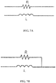
- one end of the damper resistor is connected to a terminal of the inductor. Therefore the combined damper resistor and inductor may have all four terminals brought out or have three terminals brought out, as depicted in FIGS. 7A and 7B .
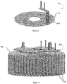
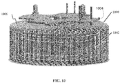
- the resistive pattern is printed on a flexible strip base substrate material and then wrapped around the toroid (as shown in FIG. 10 ), while in other arrangements (mentioned by way of background only), the resistive pattern is printed on a disk shaped flexible base material and inserted between the toroidal inductor and its housing (as shown in FIG. 9 ).
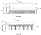
- the printed resistive pattern could be as shown in FIG. 11 or FIG. 12 for a flexible strip.
- FIGS. 1 and 2 depict filter circuits. Dampers may use a resistor (R) and capacitor (C d ) in series to form the damper 101.
- the damper is connected either across a filter inductor (L), as shown in FIG. 1 , or across the filter capacitor (C d ), as shown in FIG. 2 .
- the resistor R used in the damper is often a conventional resistor, or a thick -film resistor.
- These off-the-shelf type conventional resistors have a low mass, hence a diminished capability to handle pulse power situations. With conventional resistors, circuit reliability and life may be compromised by the in-rush energy incurred during power up and other transient power situations.
- the resistor is often made using a ceramic substrate with the resistor element printed on the inside surface of the ceramic.
- the ceramic baseplate is exposed and is used in contact with a heat sink or heat spreader for thermal management.
- the ceramic base may be prone to cracking during assembly and component handling.
- FIG. 3 depicts another filter circuit having an inductive damper 301 connected across a filter inductor (L).
- FIG. 4 depicts a conventional circuit having an inductive damper 401 connected across the filter capacitor (C d ).
- the filter inductor L d may be a toroidal-type inductor when used in aerospace applications due to its low volume and weight.
- the toroid is typically placed into a metal housing and encapsulated with thermally conductive material (a metal housing is shown with respect to FIG. 9 ).
- the metal housing provides a means for mechanical retention and thermal management.
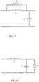
- Some filter circuit configurations may include a single resistive element (R), as shown in FIG. 5 , which depicts a simplified filter circuit having a damper resistor (R) connected across a filter inductor (L).
- FIG. 6 depicts a simplified filter circuit having a damper resistor connected across a filter capacitor.
- damper resistor ends could be brought out separately (as depicted in FIG. 7A ) or, as required by the present invention, one end of the resistor element is connected to one of the inductor leads (as depicted in FIG. 7B ).
- FIG. 8 depicts, by way of background, a resistive trace 804 printed on a flex disk 802,.
- resistive element 800 can include a resistive trace 804 (depicted as two dashed lines in FIG. 8 for simplicity).
- Flex disk 802 may be any circuit-printable substrate used for printing resistive circuits. Flex disk 802 may be flexible such that it is manipulatable around a periphery of an object.
- FIG. 9 depicts, by way of background, resistive trace 804 printed on a flex disk 802 (the edge of which depicted on the underside of a toroidal inductor housing 902).
- Flex disk 802 may be configured between toroidal inductor 904 and toroidal inductor housing 902.
- FIG. 9 shows a resistive element including a resistive trace pattern printed on a flexible insulating disk (substrate) and disposed between the bottom of toroidal inductor 902 and the housing 904.
- FIG. 10 depicts a resistive pattern on 1002 (shown in greater detail with respect to FIGS. 11 and 12 ) on a substrate 1008.
- the resistive pattern 1002 is printed on a substrate 1008 and inserted between a toroidal inductor 1004 (around an outer periphery of inductor 1004) between the inductor 1004 and a toroidal inductor housing 1006.
- Substrate 1008 may be any circuit-printable substrate used for printing resistive circuits.
- Substrate 1008 is flexible such that it is manipulatable around a periphery of an object, such as toroidal inductor housing 1006.
- FIG. 11 depicts a resistive element pattern for a strip-type resistor, according to one embodiment.
- the flexible substrate 1102 forms a rectangle having a width (w) and a length (1) that is longer than the width, where the resistive trace 1104 begins at a first end of the substrate, and traverses along width w in a zig-zag pattern from the first end of the substrate (shown on the left side of the rectangle) to a second end of the substrate (the right side of the rectangle).
- the resistive trace 1104 terminates at the first end of the substrate near the entry point. Accordingly, the resistive trace 1104 traverses along the length 1 of the rectangle 6 times before terminating at the first end of the substrate.
- Fig. 12 depicts another embodiment, wherein the flexible substrate 1102 forms a rectangle having width w and length 1 that is longer than the width, where the resistive trace 1204 begins at a first end of the substrate (shown on the left of the rectangle) and traverses along the length 1 in a zig-zag pattern from the first end of the substrate (left of the rectangle) to a second end of the substrate (to the right of the rectangle). Resistive trace 1204 terminates at the first end of the substrate.
Landscapes
- Engineering & Computer Science (AREA)
- Power Engineering (AREA)
- Microelectronics & Electronic Packaging (AREA)
- Coils Or Transformers For Communication (AREA)
- Filters And Equalizers (AREA)
Claims (4)
- Circuit amortisseur d'inducteur comprenant :un inducteur toroïdal (1004) ayant une bobine d'inducteur et un boîtier d'inducteur (1006) ; etun élément résistif configuré autour d'une périphérie de la bobine d'inducteur et ayant une extrémité reliée à l'inducteur toroïdal, caractérisé en ce que :l'élément résistif est imprimé sur un substrat flexible (1008, 1102) et relié électriquement à la bobine d'inducteur ; etl'élément résistif est intégré dans le boîtier d'inducteur avec l'inducteur toroïdal ; dans lequel le substrat flexible (1008, 1102) forme une résistance de type bande ayant une piste résistive (1002, 1104, 1204) imprimée sur celui-ci et est disposé autour d'une périphérie de la bobine d'inducteur entre une périphérie externe de la bobine d'inducteur et une périphérie interne du boîtier d'inducteur.
- Circuit amortisseur d'inducteur selon la revendication 1, dans lequel le substrat flexible (1102) forme un rectangle ayant une largeur et une longueur plus longue que la largeur, dans lequel la piste résistive (1204) commence au niveau d'une première extrémité du substrat et traverse le long de la longueur selon un motif en zig-zag jusqu'à une seconde extrémité du substrat, dans lequel la piste résistive se termine au niveau de la première extrémité du substrat.
- Circuit amortisseur d'inducteur selon la revendication 1, dans lequel le substrat flexible (1102) forme un rectangle ayant une largeur et une longueur plus longue que la largeur, dans lequel la piste résistive (1104) commence au niveau d'une première extrémité du substrat et traverse le long de la largeur selon un motif en zig-zag de la première extrémité du substrat jusqu'à une seconde extrémité du substrat, dans lequel la piste résistive se termine au niveau de la première extrémité du substrat.
- Circuit amortisseur d'inducteur selon la revendication 1, dans lequel l'élément résistif comporte une paire d'extrémités de résistance, une extrémité de résistance à partir de la paire d'extrémités de résistance étant coterminale à une extrémité d'inducteur d'une paire d'extrémités d'inducteur.
Applications Claiming Priority (1)
| Application Number | Priority Date | Filing Date | Title |
|---|---|---|---|
| US15/194,657 US10453603B2 (en) | 2016-06-28 | 2016-06-28 | Integration of inductor and damper for power filters |
Publications (2)
| Publication Number | Publication Date |
|---|---|
| EP3297006A1 EP3297006A1 (fr) | 2018-03-21 |
| EP3297006B1 true EP3297006B1 (fr) | 2019-10-09 |
Family
ID=59366190
Family Applications (1)
| Application Number | Title | Priority Date | Filing Date |
|---|---|---|---|
| EP17178310.3A Active EP3297006B1 (fr) | 2016-06-28 | 2017-06-28 | Intégration d'inducteur et amortisseur pour filtres de puissance |
Country Status (2)
| Country | Link |
|---|---|
| US (1) | US10453603B2 (fr) |
| EP (1) | EP3297006B1 (fr) |
Families Citing this family (3)
| Publication number | Priority date | Publication date | Assignee | Title |
|---|---|---|---|---|
| EP3793076A1 (fr) * | 2019-09-13 | 2021-03-17 | Hamilton Sundstrand Corporation | Filtre pour groupe motopropulseur |
| CN115172004A (zh) * | 2022-05-25 | 2022-10-11 | 上海东软医疗科技有限公司 | 一种磁性元件、滤波器和成像设备 |
| EP4418516A1 (fr) * | 2023-02-14 | 2024-08-21 | Collins Aerospace Ireland, Limited | Filtre pour un entraînement par moteur |
Family Cites Families (9)
| Publication number | Priority date | Publication date | Assignee | Title |
|---|---|---|---|---|
| GB1493369A (en) * | 1974-12-21 | 1977-11-30 | Underground Location Services | Gauging plates for pipeline testing tools |
| JPS603529Y2 (ja) | 1979-03-15 | 1985-01-31 | 松下電工株式会社 | コイル装置 |
| DE4402351C2 (de) | 1994-01-27 | 1999-01-07 | Hans M Strassner | Vorrichtung zur Unterdrückung von Brumm- und eingestreuten Störungen auf Audio-Verbindungsleitungen |
| US9300197B2 (en) | 2004-06-17 | 2016-03-29 | Grant A. MacLennan | High frequency inductor filter apparatus and method of use thereof |
| TWI243526B (en) | 2004-08-11 | 2005-11-11 | Uis Abler Electronics Co Ltd | Three-phase three-wire active power filter |
| US7068005B2 (en) | 2004-08-30 | 2006-06-27 | Hamilton Sundstrand Corporation | Motor drive with damper |
| TWI236792B (en) | 2004-08-30 | 2005-07-21 | Uis Abler Electronics Co Ltd | Active equipment for harmonic suppression |
| EP2390891A1 (fr) | 2010-05-24 | 2011-11-30 | ABB Technology AG | Dispositif de suppression d'un transitoire très rapide |
| US20130039105A1 (en) | 2011-08-09 | 2013-02-14 | Hamilton Sundstrand Corporation | Filter circuit for a multi-phase ac input |
-
2016
- 2016-06-28 US US15/194,657 patent/US10453603B2/en active Active
-
2017
- 2017-06-28 EP EP17178310.3A patent/EP3297006B1/fr active Active
Non-Patent Citations (1)
| Title |
|---|
| None * |
Also Published As
| Publication number | Publication date |
|---|---|
| US20170372835A1 (en) | 2017-12-28 |
| US10453603B2 (en) | 2019-10-22 |
| EP3297006A1 (fr) | 2018-03-21 |
Similar Documents
| Publication | Publication Date | Title |
|---|---|---|
| US8736401B2 (en) | Capacitance device and resonance circuit | |
| KR101892802B1 (ko) | 적층형 커패시터 및 그 실장 기판 | |
| EP3297006B1 (fr) | Intégration d'inducteur et amortisseur pour filtres de puissance | |
| US9916929B2 (en) | Electronic component | |
| US9881742B2 (en) | Electronic component | |
| JP2007214166A5 (fr) | ||
| CN106465548A (zh) | 树脂密封型模块 | |
| KR101602218B1 (ko) | 고정자 슬롯 온도센서 및 그 제조 방법 | |
| JP6668913B2 (ja) | 電子部品 | |
| JP5167124B2 (ja) | 低減された寄生容量を備えた電気的多層構成素子 | |
| EP3285268B1 (fr) | Agencement de filtre de puissance ayant un ensemble inducteur toroïdal | |
| KR20150080679A (ko) | 적층형 전자부품 및 그 제조방법 | |
| US3967222A (en) | Distributed resistance-capacitance component | |
| JP4807241B2 (ja) | コイル部品の実装構造 | |
| JPH0124901Y2 (fr) | ||
| JP2011077234A (ja) | 電子部品およびプリント基板 | |
| JP2010114385A (ja) | セラミック電子部品 | |
| JP6333501B1 (ja) | サージ吸収素子および電子部品 | |
| JPH0638416Y2 (ja) | 混成集積回路部品 | |
| JPS60221920A (ja) | チツプ型セラミツクヒユ−ズの製造方法 | |
| JPH1126910A (ja) | 電子部品のはんだ付け構造 | |
| JPH0416013A (ja) | ノイズ・フイルタ | |
| JP6260246B2 (ja) | 非可逆回路素子を備えたモジュール | |
| JP2001237107A (ja) | 積層型チップサーミスタ | |
| JPH0529109A (ja) | バリスタ部品 |
Legal Events
| Date | Code | Title | Description |
|---|---|---|---|
| PUAI | Public reference made under article 153(3) epc to a published international application that has entered the european phase |
Free format text: ORIGINAL CODE: 0009012 |
|
| STAA | Information on the status of an ep patent application or granted ep patent |
Free format text: STATUS: THE APPLICATION HAS BEEN PUBLISHED |
|
| AK | Designated contracting states |
Kind code of ref document: A1 Designated state(s): AL AT BE BG CH CY CZ DE DK EE ES FI FR GB GR HR HU IE IS IT LI LT LU LV MC MK MT NL NO PL PT RO RS SE SI SK SM TR |
|
| AX | Request for extension of the european patent |
Extension state: BA ME |
|
| STAA | Information on the status of an ep patent application or granted ep patent |
Free format text: STATUS: REQUEST FOR EXAMINATION WAS MADE |
|
| 17P | Request for examination filed |
Effective date: 20180921 |
|
| RBV | Designated contracting states (corrected) |
Designated state(s): AL AT BE BG CH CY CZ DE DK EE ES FI FR GB GR HR HU IE IS IT LI LT LU LV MC MK MT NL NO PL PT RO RS SE SI SK SM TR |
|
| GRAP | Despatch of communication of intention to grant a patent |
Free format text: ORIGINAL CODE: EPIDOSNIGR1 |
|
| STAA | Information on the status of an ep patent application or granted ep patent |
Free format text: STATUS: GRANT OF PATENT IS INTENDED |
|
| INTG | Intention to grant announced |
Effective date: 20190424 |
|
| GRAS | Grant fee paid |
Free format text: ORIGINAL CODE: EPIDOSNIGR3 |
|
| GRAA | (expected) grant |
Free format text: ORIGINAL CODE: 0009210 |
|
| STAA | Information on the status of an ep patent application or granted ep patent |
Free format text: STATUS: THE PATENT HAS BEEN GRANTED |
|
| AK | Designated contracting states |
Kind code of ref document: B1 Designated state(s): AL AT BE BG CH CY CZ DE DK EE ES FI FR GB GR HR HU IE IS IT LI LT LU LV MC MK MT NL NO PL PT RO RS SE SI SK SM TR |
|
| REG | Reference to a national code |
Ref country code: GB Ref legal event code: FG4D |
|
| REG | Reference to a national code |
Ref country code: CH Ref legal event code: EP |
|
| REG | Reference to a national code |
Ref country code: IE Ref legal event code: FG4D |
|
| REG | Reference to a national code |
Ref country code: DE Ref legal event code: R096 Ref document number: 602017007578 Country of ref document: DE |
|
| REG | Reference to a national code |
Ref country code: AT Ref legal event code: REF Ref document number: 1189774 Country of ref document: AT Kind code of ref document: T Effective date: 20191115 |
|
| REG | Reference to a national code |
Ref country code: NL Ref legal event code: MP Effective date: 20191009 |
|
| REG | Reference to a national code |
Ref country code: LT Ref legal event code: MG4D |
|
| REG | Reference to a national code |
Ref country code: AT Ref legal event code: MK05 Ref document number: 1189774 Country of ref document: AT Kind code of ref document: T Effective date: 20191009 |
|
| PG25 | Lapsed in a contracting state [announced via postgrant information from national office to epo] |
Ref country code: FI Free format text: LAPSE BECAUSE OF FAILURE TO SUBMIT A TRANSLATION OF THE DESCRIPTION OR TO PAY THE FEE WITHIN THE PRESCRIBED TIME-LIMIT Effective date: 20191009 Ref country code: BG Free format text: LAPSE BECAUSE OF FAILURE TO SUBMIT A TRANSLATION OF THE DESCRIPTION OR TO PAY THE FEE WITHIN THE PRESCRIBED TIME-LIMIT Effective date: 20200109 Ref country code: GR Free format text: LAPSE BECAUSE OF FAILURE TO SUBMIT A TRANSLATION OF THE DESCRIPTION OR TO PAY THE FEE WITHIN THE PRESCRIBED TIME-LIMIT Effective date: 20200110 Ref country code: AT Free format text: LAPSE BECAUSE OF FAILURE TO SUBMIT A TRANSLATION OF THE DESCRIPTION OR TO PAY THE FEE WITHIN THE PRESCRIBED TIME-LIMIT Effective date: 20191009 Ref country code: PT Free format text: LAPSE BECAUSE OF FAILURE TO SUBMIT A TRANSLATION OF THE DESCRIPTION OR TO PAY THE FEE WITHIN THE PRESCRIBED TIME-LIMIT Effective date: 20200210 Ref country code: ES Free format text: LAPSE BECAUSE OF FAILURE TO SUBMIT A TRANSLATION OF THE DESCRIPTION OR TO PAY THE FEE WITHIN THE PRESCRIBED TIME-LIMIT Effective date: 20191009 Ref country code: SE Free format text: LAPSE BECAUSE OF FAILURE TO SUBMIT A TRANSLATION OF THE DESCRIPTION OR TO PAY THE FEE WITHIN THE PRESCRIBED TIME-LIMIT Effective date: 20191009 Ref country code: LV Free format text: LAPSE BECAUSE OF FAILURE TO SUBMIT A TRANSLATION OF THE DESCRIPTION OR TO PAY THE FEE WITHIN THE PRESCRIBED TIME-LIMIT Effective date: 20191009 Ref country code: NL Free format text: LAPSE BECAUSE OF FAILURE TO SUBMIT A TRANSLATION OF THE DESCRIPTION OR TO PAY THE FEE WITHIN THE PRESCRIBED TIME-LIMIT Effective date: 20191009 Ref country code: PL Free format text: LAPSE BECAUSE OF FAILURE TO SUBMIT A TRANSLATION OF THE DESCRIPTION OR TO PAY THE FEE WITHIN THE PRESCRIBED TIME-LIMIT Effective date: 20191009 Ref country code: LT Free format text: LAPSE BECAUSE OF FAILURE TO SUBMIT A TRANSLATION OF THE DESCRIPTION OR TO PAY THE FEE WITHIN THE PRESCRIBED TIME-LIMIT Effective date: 20191009 Ref country code: NO Free format text: LAPSE BECAUSE OF FAILURE TO SUBMIT A TRANSLATION OF THE DESCRIPTION OR TO PAY THE FEE WITHIN THE PRESCRIBED TIME-LIMIT Effective date: 20200109 |
|
| PG25 | Lapsed in a contracting state [announced via postgrant information from national office to epo] |
Ref country code: IS Free format text: LAPSE BECAUSE OF FAILURE TO SUBMIT A TRANSLATION OF THE DESCRIPTION OR TO PAY THE FEE WITHIN THE PRESCRIBED TIME-LIMIT Effective date: 20200224 Ref country code: HR Free format text: LAPSE BECAUSE OF FAILURE TO SUBMIT A TRANSLATION OF THE DESCRIPTION OR TO PAY THE FEE WITHIN THE PRESCRIBED TIME-LIMIT Effective date: 20191009 Ref country code: RS Free format text: LAPSE BECAUSE OF FAILURE TO SUBMIT A TRANSLATION OF THE DESCRIPTION OR TO PAY THE FEE WITHIN THE PRESCRIBED TIME-LIMIT Effective date: 20191009 |
|
| PG25 | Lapsed in a contracting state [announced via postgrant information from national office to epo] |
Ref country code: AL Free format text: LAPSE BECAUSE OF FAILURE TO SUBMIT A TRANSLATION OF THE DESCRIPTION OR TO PAY THE FEE WITHIN THE PRESCRIBED TIME-LIMIT Effective date: 20191009 |
|
| REG | Reference to a national code |
Ref country code: DE Ref legal event code: R097 Ref document number: 602017007578 Country of ref document: DE |
|
| PG2D | Information on lapse in contracting state deleted |
Ref country code: IS |
|
| PG25 | Lapsed in a contracting state [announced via postgrant information from national office to epo] |
Ref country code: CZ Free format text: LAPSE BECAUSE OF FAILURE TO SUBMIT A TRANSLATION OF THE DESCRIPTION OR TO PAY THE FEE WITHIN THE PRESCRIBED TIME-LIMIT Effective date: 20191009 Ref country code: RO Free format text: LAPSE BECAUSE OF FAILURE TO SUBMIT A TRANSLATION OF THE DESCRIPTION OR TO PAY THE FEE WITHIN THE PRESCRIBED TIME-LIMIT Effective date: 20191009 Ref country code: EE Free format text: LAPSE BECAUSE OF FAILURE TO SUBMIT A TRANSLATION OF THE DESCRIPTION OR TO PAY THE FEE WITHIN THE PRESCRIBED TIME-LIMIT Effective date: 20191009 Ref country code: DK Free format text: LAPSE BECAUSE OF FAILURE TO SUBMIT A TRANSLATION OF THE DESCRIPTION OR TO PAY THE FEE WITHIN THE PRESCRIBED TIME-LIMIT Effective date: 20191009 Ref country code: IS Free format text: LAPSE BECAUSE OF FAILURE TO SUBMIT A TRANSLATION OF THE DESCRIPTION OR TO PAY THE FEE WITHIN THE PRESCRIBED TIME-LIMIT Effective date: 20200209 |
|
| PLBE | No opposition filed within time limit |
Free format text: ORIGINAL CODE: 0009261 |
|
| STAA | Information on the status of an ep patent application or granted ep patent |
Free format text: STATUS: NO OPPOSITION FILED WITHIN TIME LIMIT |
|
| PG25 | Lapsed in a contracting state [announced via postgrant information from national office to epo] |
Ref country code: SK Free format text: LAPSE BECAUSE OF FAILURE TO SUBMIT A TRANSLATION OF THE DESCRIPTION OR TO PAY THE FEE WITHIN THE PRESCRIBED TIME-LIMIT Effective date: 20191009 Ref country code: SM Free format text: LAPSE BECAUSE OF FAILURE TO SUBMIT A TRANSLATION OF THE DESCRIPTION OR TO PAY THE FEE WITHIN THE PRESCRIBED TIME-LIMIT Effective date: 20191009 Ref country code: IT Free format text: LAPSE BECAUSE OF FAILURE TO SUBMIT A TRANSLATION OF THE DESCRIPTION OR TO PAY THE FEE WITHIN THE PRESCRIBED TIME-LIMIT Effective date: 20191009 |
|
| 26N | No opposition filed |
Effective date: 20200710 |
|
| PG25 | Lapsed in a contracting state [announced via postgrant information from national office to epo] |
Ref country code: SI Free format text: LAPSE BECAUSE OF FAILURE TO SUBMIT A TRANSLATION OF THE DESCRIPTION OR TO PAY THE FEE WITHIN THE PRESCRIBED TIME-LIMIT Effective date: 20191009 |
|
| PG25 | Lapsed in a contracting state [announced via postgrant information from national office to epo] |
Ref country code: MC Free format text: LAPSE BECAUSE OF FAILURE TO SUBMIT A TRANSLATION OF THE DESCRIPTION OR TO PAY THE FEE WITHIN THE PRESCRIBED TIME-LIMIT Effective date: 20191009 |
|
| REG | Reference to a national code |
Ref country code: CH Ref legal event code: PL |
|
| PG25 | Lapsed in a contracting state [announced via postgrant information from national office to epo] |
Ref country code: LU Free format text: LAPSE BECAUSE OF NON-PAYMENT OF DUE FEES Effective date: 20200628 |
|
| REG | Reference to a national code |
Ref country code: BE Ref legal event code: MM Effective date: 20200630 |
|
| PG25 | Lapsed in a contracting state [announced via postgrant information from national office to epo] |
Ref country code: CH Free format text: LAPSE BECAUSE OF NON-PAYMENT OF DUE FEES Effective date: 20200630 Ref country code: LI Free format text: LAPSE BECAUSE OF NON-PAYMENT OF DUE FEES Effective date: 20200630 Ref country code: IE Free format text: LAPSE BECAUSE OF NON-PAYMENT OF DUE FEES Effective date: 20200628 |
|
| PG25 | Lapsed in a contracting state [announced via postgrant information from national office to epo] |
Ref country code: BE Free format text: LAPSE BECAUSE OF NON-PAYMENT OF DUE FEES Effective date: 20200630 |
|
| PG25 | Lapsed in a contracting state [announced via postgrant information from national office to epo] |
Ref country code: TR Free format text: LAPSE BECAUSE OF FAILURE TO SUBMIT A TRANSLATION OF THE DESCRIPTION OR TO PAY THE FEE WITHIN THE PRESCRIBED TIME-LIMIT Effective date: 20191009 Ref country code: MT Free format text: LAPSE BECAUSE OF FAILURE TO SUBMIT A TRANSLATION OF THE DESCRIPTION OR TO PAY THE FEE WITHIN THE PRESCRIBED TIME-LIMIT Effective date: 20191009 Ref country code: CY Free format text: LAPSE BECAUSE OF FAILURE TO SUBMIT A TRANSLATION OF THE DESCRIPTION OR TO PAY THE FEE WITHIN THE PRESCRIBED TIME-LIMIT Effective date: 20191009 |
|
| PG25 | Lapsed in a contracting state [announced via postgrant information from national office to epo] |
Ref country code: MK Free format text: LAPSE BECAUSE OF FAILURE TO SUBMIT A TRANSLATION OF THE DESCRIPTION OR TO PAY THE FEE WITHIN THE PRESCRIBED TIME-LIMIT Effective date: 20191009 |
|
| P01 | Opt-out of the competence of the unified patent court (upc) registered |
Effective date: 20230522 |
|
| PGFP | Annual fee paid to national office [announced via postgrant information from national office to epo] |
Ref country code: DE Payment date: 20250520 Year of fee payment: 9 |
|
| PGFP | Annual fee paid to national office [announced via postgrant information from national office to epo] |
Ref country code: GB Payment date: 20250520 Year of fee payment: 9 |
|
| PGFP | Annual fee paid to national office [announced via postgrant information from national office to epo] |
Ref country code: FR Payment date: 20250520 Year of fee payment: 9 |