EP3297014A1 - Appareil de commutation haute tension et installation de commutation comprenant un appareil de commutation haute tension et procede de production d'un appareil de commutation haute tension - Google Patents
Appareil de commutation haute tension et installation de commutation comprenant un appareil de commutation haute tension et procede de production d'un appareil de commutation haute tension Download PDFInfo
- Publication number
- EP3297014A1 EP3297014A1 EP16189608.9A EP16189608A EP3297014A1 EP 3297014 A1 EP3297014 A1 EP 3297014A1 EP 16189608 A EP16189608 A EP 16189608A EP 3297014 A1 EP3297014 A1 EP 3297014A1
- Authority
- EP
- European Patent Office
- Prior art keywords
- vacuum chamber
- resin layer
- voltage switching
- switching device
- housing body
- Prior art date
- Legal status (The legal status is an assumption and is not a legal conclusion. Google has not performed a legal analysis and makes no representation as to the accuracy of the status listed.)
- Granted
Links
Images


Classifications
-
- H—ELECTRICITY
- H01—ELECTRIC ELEMENTS
- H01H—ELECTRIC SWITCHES; RELAYS; SELECTORS; EMERGENCY PROTECTIVE DEVICES
- H01H33/00—High-tension or heavy-current switches with arc-extinguishing or arc-preventing means
- H01H33/60—Switches wherein the means for extinguishing or preventing the arc do not include separate means for obtaining or increasing flow of arc-extinguishing fluid
- H01H33/66—Vacuum switches
- H01H33/662—Housings or protective screens
- H01H33/66207—Specific housing details, e.g. sealing, soldering or brazing
- H01H2033/66223—Details relating to the sealing of vacuum switch housings
-
- H—ELECTRICITY
- H01—ELECTRIC ELEMENTS
- H01H—ELECTRIC SWITCHES; RELAYS; SELECTORS; EMERGENCY PROTECTIVE DEVICES
- H01H33/00—High-tension or heavy-current switches with arc-extinguishing or arc-preventing means
- H01H33/60—Switches wherein the means for extinguishing or preventing the arc do not include separate means for obtaining or increasing flow of arc-extinguishing fluid
- H01H33/66—Vacuum switches
- H01H33/662—Housings or protective screens
- H01H33/66207—Specific housing details, e.g. sealing, soldering or brazing
- H01H2033/6623—Details relating to the encasing or the outside layers of the vacuum switch housings
-
- H—ELECTRICITY
- H01—ELECTRIC ELEMENTS
- H01H—ELECTRIC SWITCHES; RELAYS; SELECTORS; EMERGENCY PROTECTIVE DEVICES
- H01H33/00—High-tension or heavy-current switches with arc-extinguishing or arc-preventing means
- H01H33/60—Switches wherein the means for extinguishing or preventing the arc do not include separate means for obtaining or increasing flow of arc-extinguishing fluid
- H01H33/66—Vacuum switches
- H01H33/666—Operating arrangements
- H01H2033/6665—Details concerning the mounting or supporting of the individual vacuum bottles
-
- H—ELECTRICITY
- H01—ELECTRIC ELEMENTS
- H01H—ELECTRIC SWITCHES; RELAYS; SELECTORS; EMERGENCY PROTECTIVE DEVICES
- H01H2229/00—Manufacturing
- H01H2229/044—Injection moulding
Definitions
- Switchgear with vacuum chamber are for example from the DE 31 12 776 A1 and DE 40 27 723 A1 known.
- the known vacuum chambers have a housing body in which an immovable switching contact and a movable switching contact are arranged.
- the movable switching contact is actuated by an actuating unit.
- the drive of the actuator can be done with an electric drive unit.
- the vacuum chamber is inserted into a casting mold and sealed with a potting compound, such as epoxy, so that the vacuum chamber is enclosed by a solid potting after curing of the potting compound.
- the high-voltage switching device flows through current during operation, the power loss is released in the form of heat.
- the components of the housing body of the vacuum chamber which may be made of ceramic or metallic materials, such as copper, expand more than the solid potting housing.
- mechanical stresses and associated fine cracks in the solid plastic potting arise.
- the life of the switching device can thus be significantly reduced. In addition, unexpected rollovers can occur.
- the invention has for its object to reduce the risk of flashovers in high-voltage switchgear and switchgear with high-voltage switchgear. Another object of the invention is to provide a method with which a high-voltage switching device can be produced with improved electrical properties.
- the high-voltage switching device comprises a casting housing made of a casting resin, which encloses the housing body of the vacuum chamber, which has a fixed contact, which may be a switching or isolating contact, and a movable contact, which may be a switching or isolating contact, wherein between the inner wall of the potting and the outer wall of the housing body of the vacuum chamber, an intermediate layer is provided.
- This intermediate layer is a casting resin layer, wherein the glass transition temperature of the casting resin layer is between 10 and 40 ° C.
- the glass transition temperature of the casting resin layer is between 20 and 30 ° C. The glass transition temperature gives an indication of the dimensional stability of the plastic when exposed to heat.
- the modulus of elasticity of the casting resin of the casting resin layer of the vacuum chamber is less than 1000 MPa.
- the modulus of elasticity of the cast resin layer is greater than 100 MPa, more preferably greater than 500 MPa.
- a cast resin layer having a tensile strength of less than 20 MPa has proved to be particularly advantageous.
- the casting resin is preferably an epoxy resin.
- the plastic body may consist of one or more plastic elements which are interconnected.
- the plastic body consists of several plastic elements that can be easily and inexpensively manufactured by injection molding and then can be connected together. Individual plastic elements can be plugged into each other and / or glued or welded together. With the use of a plastic body not only the electrical properties of the switching device can be improved, but also its manufacture can be simplified.
- the cast resin layer may be applied to the housing body of the vacuum chamber by the method known in the art.
- the casting resin layer is applied by a pressure gelling or vacuum method so that the formation of air bubbles can be avoided.
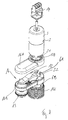
- Fig. 1 shows the essential components of the invention of the high-voltage switching device
- Fig. 2 the vacuum chamber of the switching device shows.
- the corresponding parts are provided in the figures with the same reference numerals.
- the vacuum chamber may include, for example, a vacuum switching chamber for switching load currents or short-circuit currents in a circuit breaker or a vacuum isolation chamber for a circuit breaker or earthing switch or combined Be a switch. The invention will be described below with reference to a circuit breaker.
- an intermediate layer 3A made of a casting resin, which is more flexible than the casting resin of the potting 1.
- the flexible casting resin has a glass transition temperature (Tg) which is between 10 and 40 ° C.
- Tg glass transition temperature
- the maximum tensile stress (tensile strength) of the casting resin is less than 20 MPa and the elongation at break (tensile strength) greater than 9%.
- the elastic modulus (modulus of elasticity) of the casting resin is less than 1000 MPa.
- the modulus of elasticity of Casting resin greater than 100 MPa, more preferably greater than 500 MPa, in particular about 600 MPa.
- Araldite® Heuntsman Advanced Materials
- Araldite® S-HCEP or Araldite® CW 1491 / HW 1491 has proven to be particularly advantageous.
- the actuator 8 has an upper, hollow cylindrical portion 8A, which is located in the chamber 6 and a lower, pin-shaped portion 8B, which is longitudinally displaceably guided in the cylinder space of the upper portion and extending from the chamber 6.
- the upper end portion of the lower portion 8B is supported on a compression spring 9 in the cylinder space of the upper portion 8A. If the lower one Section 8 B is moved, also shifts the upper portion 8 A, so that the movable switching contact element 5 is displaced axially.
- the compression spring 9 serves to damp the shocks during the actuation of the actuating member 8.
- the drive of the actuator 8 is effected with a drive unit, not shown, which moves the lower portion 8 B in the axial direction.
- the plastic body 16 in the lower housing half 1B of the potting housing 1 is composed of a plurality of plastic elements 16A, 16B, 16C.
- Fig. 3 shows the plastic elements 16A, 16B, 16C in an exploded view.
- the plastic body 16 has in the upper half of the chamber 6A an upper shell-shaped plastic element 16A and a lower, shell-shaped plastic elements 16B which surround the movable conductor part 12, and has in the lower chamber half 6B a cylindrical plastic element 16C which surrounds the bellows 11.
- the plastic members 16A, 16B, 16C are formed so that they can be assembled properly. They are tightly inserted into each other and / or glued or welded together. All plastic elements 16A, 16B, 16C have rounded corners or edges.
- the cover 13 of the potting housing 1, which closes the liquid-filled chamber 6, is sealed in a liquid-tight manner with respect to the cylindrical plastic part 16C with a sealing ring 18 located between the cover and the plastic part.
- the housing body 1 of the vacuum chamber 2 is inserted into a casting mold, not shown, which may consist of two mold halves, and in the space between the inner wall of the mold halves and the outer wall of the Housing body 3, the casting resin is filled.
- the coating or coating of the housing body 3 can be done with the known Druckgeliervon.
- the filling pressure should be above 1 bar. Typical values are 3 to 7 bar. So a bubble-free casting can be guaranteed.
- a casting mold for the production of the potting housing 1 of the switching device, a casting mold, not shown in the figures is used, which is designed such that the shape and dimensions of the potting 1 and the shape and dimensions of the provided with the casting resin layer 3A vacuum chamber 2 and the rest Components of the switching device corresponds.
- the vacuum chamber 2 is used, wherein between the inner wall of the casting mold and the outer wall of the vacuum chamber 2, a gap 19 remains.
- the plastic body 16 is used, wherein between the wall of the casting mold and the plastic body 16, a gap 20 remains. Subsequently, the intermediate spaces 19, 20 are cast between casting mold and vacuum chamber or plastic body with a potting material, which has the material properties described above.
Landscapes
- High-Tension Arc-Extinguishing Switches Without Spraying Means (AREA)
- Manufacture Of Switches (AREA)
Priority Applications (8)
| Application Number | Priority Date | Filing Date | Title |
|---|---|---|---|
| EP16189608.9A EP3297014B1 (fr) | 2016-09-20 | 2016-09-20 | Appareil de commutation haute tension et installation de commutation comprenant un appareil de commutation haute tension et procede de production d'un appareil de commutation haute tension |
| SI201631389T SI3297014T1 (sl) | 2016-09-20 | 2016-09-20 | Visokonapetostna stikalna naprava in stikalna inštalacija z visokonapetostno stikalno napravo ter postopek za izdelavo visokonapetostne stikalne naprave |
| PT161896089T PT3297014T (pt) | 2016-09-20 | 2016-09-20 | Dispositivo de comutação de alta tensão e circuito de comutação com um dispositivo de comutação de alta tensão e método para produzir um dispositivo de comutação de alta tensão |
| PL16189608T PL3297014T3 (pl) | 2016-09-20 | 2016-09-20 | Łącznik wysokonapięciowy i rozdzielnia z łącznikiem wysokonapięciowym i sposób wytwarzania łącznika wysokonapięciowego |
| HUE16189608A HUE056256T2 (hu) | 2016-09-20 | 2016-09-20 | Nagyfeszültségû kapcsolóberendezés és kapcsoló egység egy nagyfeszültségû kapcsolóberendezéssel és eljárás egy nagyfeszültségû kapcsolóberendezés elõállítására |
| PCT/EP2017/073522 WO2018054851A1 (fr) | 2016-09-20 | 2017-09-18 | Dispositif de commutation à haute tension et installation de commutation équipée d'un dispositif de commutation à haute tension et procédé de fabrication d'un dispositif de commutation à haute tension |
| CN201780057460.XA CN109791858B (zh) | 2016-09-20 | 2017-09-18 | 高压开关装置和带有高压开关装置的开关设备以及高压开关装置的制造方法 |
| US16/333,636 US20190259554A1 (en) | 2016-09-20 | 2017-09-18 | High-Voltage Switching Device and Switching System Comprising a High-Voltage Switching Device and Method for Manufacturing a High-Voltage Switching Device |
Applications Claiming Priority (1)
| Application Number | Priority Date | Filing Date | Title |
|---|---|---|---|
| EP16189608.9A EP3297014B1 (fr) | 2016-09-20 | 2016-09-20 | Appareil de commutation haute tension et installation de commutation comprenant un appareil de commutation haute tension et procede de production d'un appareil de commutation haute tension |
Publications (2)
| Publication Number | Publication Date |
|---|---|
| EP3297014A1 true EP3297014A1 (fr) | 2018-03-21 |
| EP3297014B1 EP3297014B1 (fr) | 2021-08-11 |
Family
ID=56958832
Family Applications (1)
| Application Number | Title | Priority Date | Filing Date |
|---|---|---|---|
| EP16189608.9A Active EP3297014B1 (fr) | 2016-09-20 | 2016-09-20 | Appareil de commutation haute tension et installation de commutation comprenant un appareil de commutation haute tension et procede de production d'un appareil de commutation haute tension |
Country Status (8)
| Country | Link |
|---|---|
| US (1) | US20190259554A1 (fr) |
| EP (1) | EP3297014B1 (fr) |
| CN (1) | CN109791858B (fr) |
| HU (1) | HUE056256T2 (fr) |
| PL (1) | PL3297014T3 (fr) |
| PT (1) | PT3297014T (fr) |
| SI (1) | SI3297014T1 (fr) |
| WO (1) | WO2018054851A1 (fr) |
Cited By (1)
| Publication number | Priority date | Publication date | Assignee | Title |
|---|---|---|---|---|
| CN111696819A (zh) * | 2020-05-13 | 2020-09-22 | 平高集团有限公司 | 一种固封极柱及使用该固封极柱的环网柜 |
Families Citing this family (3)
| Publication number | Priority date | Publication date | Assignee | Title |
|---|---|---|---|---|
| US12266490B2 (en) | 2019-04-26 | 2025-04-01 | G & W Electric Company | Modular recloser |
| PH12021552689A1 (en) | 2019-04-26 | 2022-03-14 | G & W Electric | Switchgear with overmolded dielectric material |
| WO2020219905A1 (fr) | 2019-04-26 | 2020-10-29 | G & W Electric Company | Appareillage de commutation avec ensemble de déclenchement manuel et verrouillage mécanique |
Citations (6)
| Publication number | Priority date | Publication date | Assignee | Title |
|---|---|---|---|---|
| DE3112776A1 (de) | 1981-03-31 | 1982-10-28 | Wickmann-Werke Böblingen GmbH, 7030 Böblingen | Schaltvorrichtung mit einem vakuum-unterbrecher zwischen einer sammelschiene und einem kabelanschlussstutzen |
| DE4027723A1 (de) | 1990-08-30 | 1991-01-10 | Slamecka Ernst | Vakuumschaltkammer fuer lasttrennschalter |
| JPH06231661A (ja) * | 1993-02-09 | 1994-08-19 | Toshiba Corp | 樹脂モールド真空バルブ及びその製造方法 |
| DE102004060274A1 (de) * | 2004-12-15 | 2006-06-29 | Abb Patent Gmbh | Verfahren zur Herstellung eines Schalters für die Mittel- und Hochspannungstechnik, sowie ein Schalter selbst |
| DE102005039555A1 (de) * | 2005-08-22 | 2007-03-01 | Abb Technology Ltd. | Verfahren zur Herstellung von Schalterpolteilen für Nieder - Mittel - und Hochspannungsschaltanlagen, sowie Schalterpolteil selbst |
| WO2015024230A1 (fr) * | 2013-08-22 | 2015-02-26 | Dow Global Technologies Llc | Procédé de production de parties de pôle de disjoncteur |
Family Cites Families (9)
| Publication number | Priority date | Publication date | Assignee | Title |
|---|---|---|---|---|
| US3812314A (en) * | 1971-08-23 | 1974-05-21 | Gen Electric | High power electrical bushing having a vacuum switch encapsulated therein |
| US4880947A (en) * | 1988-06-29 | 1989-11-14 | Westinghouse Electric Corp. | Vacuum interrupter with simplified enclosure and method of assembly |
| WO2000041199A1 (fr) * | 1999-01-06 | 2000-07-13 | Nu-Lec Industries Pty Ltd | Procede d'assemblage de logements isoles pour materiel electrique et incorporation d'interrupteurs de circuit dans ces logements |
| JP2001043022A (ja) * | 1999-07-30 | 2001-02-16 | Matsushita Electric Ind Co Ltd | 透明タッチパネルおよびこれを用いた電子機器 |
| JP4622705B2 (ja) * | 2005-07-01 | 2011-02-02 | パナソニック株式会社 | パネルスイッチ用可動接点体 |
| EP2407990A1 (fr) * | 2010-07-15 | 2012-01-18 | ABB Technology AG | Élément de pôle de disjoncteur et procédé de production d'un tel élément de pôle |
| FR3009643B1 (fr) * | 2013-08-09 | 2015-08-07 | Schneider Electric Ind Sas | Ampoule a vide, pole de disjoncteur comprenant une telle ampoule a vide et procedes de fabrication de tels dispositifs |
| CN203910648U (zh) * | 2014-05-26 | 2014-10-29 | 北京合纵实科电力科技有限公司 | 一种户外柱上真空断路器固封极柱 |
| CN104319088A (zh) * | 2014-10-11 | 2015-01-28 | 天津市滨海纽泰克电气有限公司 | 一种真空环氧树脂浇注式互感器的制备工艺 |
-
2016
- 2016-09-20 PT PT161896089T patent/PT3297014T/pt unknown
- 2016-09-20 PL PL16189608T patent/PL3297014T3/pl unknown
- 2016-09-20 HU HUE16189608A patent/HUE056256T2/hu unknown
- 2016-09-20 SI SI201631389T patent/SI3297014T1/sl unknown
- 2016-09-20 EP EP16189608.9A patent/EP3297014B1/fr active Active
-
2017
- 2017-09-18 WO PCT/EP2017/073522 patent/WO2018054851A1/fr not_active Ceased
- 2017-09-18 US US16/333,636 patent/US20190259554A1/en not_active Abandoned
- 2017-09-18 CN CN201780057460.XA patent/CN109791858B/zh active Active
Patent Citations (6)
| Publication number | Priority date | Publication date | Assignee | Title |
|---|---|---|---|---|
| DE3112776A1 (de) | 1981-03-31 | 1982-10-28 | Wickmann-Werke Böblingen GmbH, 7030 Böblingen | Schaltvorrichtung mit einem vakuum-unterbrecher zwischen einer sammelschiene und einem kabelanschlussstutzen |
| DE4027723A1 (de) | 1990-08-30 | 1991-01-10 | Slamecka Ernst | Vakuumschaltkammer fuer lasttrennschalter |
| JPH06231661A (ja) * | 1993-02-09 | 1994-08-19 | Toshiba Corp | 樹脂モールド真空バルブ及びその製造方法 |
| DE102004060274A1 (de) * | 2004-12-15 | 2006-06-29 | Abb Patent Gmbh | Verfahren zur Herstellung eines Schalters für die Mittel- und Hochspannungstechnik, sowie ein Schalter selbst |
| DE102005039555A1 (de) * | 2005-08-22 | 2007-03-01 | Abb Technology Ltd. | Verfahren zur Herstellung von Schalterpolteilen für Nieder - Mittel - und Hochspannungsschaltanlagen, sowie Schalterpolteil selbst |
| WO2015024230A1 (fr) * | 2013-08-22 | 2015-02-26 | Dow Global Technologies Llc | Procédé de production de parties de pôle de disjoncteur |
Cited By (1)
| Publication number | Priority date | Publication date | Assignee | Title |
|---|---|---|---|---|
| CN111696819A (zh) * | 2020-05-13 | 2020-09-22 | 平高集团有限公司 | 一种固封极柱及使用该固封极柱的环网柜 |
Also Published As
| Publication number | Publication date |
|---|---|
| PT3297014T (pt) | 2021-11-04 |
| HUE056256T2 (hu) | 2022-02-28 |
| CN109791858A (zh) | 2019-05-21 |
| SI3297014T1 (sl) | 2022-03-31 |
| PL3297014T3 (pl) | 2022-01-17 |
| US20190259554A1 (en) | 2019-08-22 |
| CN109791858B (zh) | 2022-12-27 |
| WO2018054851A1 (fr) | 2018-03-29 |
| EP3297014B1 (fr) | 2021-08-11 |
Similar Documents
| Publication | Publication Date | Title |
|---|---|---|
| EP3297014B1 (fr) | Appareil de commutation haute tension et installation de commutation comprenant un appareil de commutation haute tension et procede de production d'un appareil de commutation haute tension | |
| DE202010014320U1 (de) | Vorrichtung zur Herstellung eines Leistungsschalter-Polteils | |
| EP1792325B1 (fr) | Couche elastomere auto-adhesive dans des poles de commutateur isoles par solides | |
| DE2314675A1 (de) | Isolierkoerper | |
| EP2245639A1 (fr) | Isolateur à haute tension | |
| DE10139624C1 (de) | Elektrisches Schaltgerät für Mittel- oder Hochspannung | |
| DE4015929A1 (de) | Isolator | |
| EP0920705B2 (fr) | Commutateur en charge | |
| EP3297013B1 (fr) | Appareil de commutation haute tension et installation de commutation comprenant un appareil de commutation haute tension et procede de production d'un appareil de commutation haute tension | |
| WO2024083488A1 (fr) | Module de base pour dispositifs de commutation à haute tension avec interrupteurs à vide, et dispositif de commutation à haute tension comprenant le module de base | |
| DE102016108246A1 (de) | Doppelkontakt-Schalter mit Vakuumschaltkammern | |
| DD241810A1 (de) | Schalterpol fuer leistungsschalter | |
| DE3133999A1 (de) | Gasisolierte durchfuehrung | |
| EP3011575B1 (fr) | Dispositif de transfert de forces | |
| EP1091466B1 (fr) | Boíte d'extrémité de câbles pour câbles à haute tension | |
| DE2541446A1 (de) | Hochspannungs-lastschalter | |
| EP2854246B1 (fr) | Procédé de fabrication d'un isolateur à disque pour la fermeture d'un boîtier étanche aux fluides, isolateur à disque fabriqué selon ce procédé et paratonnerre isolé contre les gaz doté d'un tel isolateur à disque | |
| EP3639286B1 (fr) | Disjoncteur à vide à contacts en double | |
| DE1189177B (de) | Metallgekapselte Hochspannungsschaltanlage | |
| DE2347945C3 (de) | Vakuumschalter | |
| WO2025223702A1 (fr) | Agencement pour commuter des tensions élevées ayant un interrupteur à vide et son procédé de fabrication | |
| DE102020202530A1 (de) | Elektrisches Betriebsmittel und Verfahren zum Schalten eines elektrischen Betriebsmittels | |
| DE102023209613A1 (de) | Anordnung von Vakuumschaltröhren zum Schalten von Hochspannungen | |
| DE102014213612A1 (de) | Teleskopieranordnung | |
| WO2025067726A1 (fr) | Interrupteur à vide pour commuter des tensions élevées, et agencement comprenant cet interrupteur à vide |
Legal Events
| Date | Code | Title | Description |
|---|---|---|---|
| PUAI | Public reference made under article 153(3) epc to a published international application that has entered the european phase |
Free format text: ORIGINAL CODE: 0009012 |
|
| STAA | Information on the status of an ep patent application or granted ep patent |
Free format text: STATUS: REQUEST FOR EXAMINATION WAS MADE |
|
| 17P | Request for examination filed |
Effective date: 20161124 |
|
| AK | Designated contracting states |
Kind code of ref document: A1 Designated state(s): AL AT BE BG CH CY CZ DE DK EE ES FI FR GB GR HR HU IE IS IT LI LT LU LV MC MK MT NL NO PL PT RO RS SE SI SK SM TR |
|
| AX | Request for extension of the european patent |
Extension state: BA ME |
|
| GRAP | Despatch of communication of intention to grant a patent |
Free format text: ORIGINAL CODE: EPIDOSNIGR1 |
|
| STAA | Information on the status of an ep patent application or granted ep patent |
Free format text: STATUS: GRANT OF PATENT IS INTENDED |
|
| INTG | Intention to grant announced |
Effective date: 20210312 |
|
| GRAS | Grant fee paid |
Free format text: ORIGINAL CODE: EPIDOSNIGR3 |
|
| GRAA | (expected) grant |
Free format text: ORIGINAL CODE: 0009210 |
|
| STAA | Information on the status of an ep patent application or granted ep patent |
Free format text: STATUS: THE PATENT HAS BEEN GRANTED |
|
| AK | Designated contracting states |
Kind code of ref document: B1 Designated state(s): AL AT BE BG CH CY CZ DE DK EE ES FI FR GB GR HR HU IE IS IT LI LT LU LV MC MK MT NL NO PL PT RO RS SE SI SK SM TR |
|
| REG | Reference to a national code |
Ref country code: CH Ref legal event code: EP |
|
| REG | Reference to a national code |
Ref country code: DE Ref legal event code: R096 Ref document number: 502016013587 Country of ref document: DE |
|
| REG | Reference to a national code |
Ref country code: IE Ref legal event code: FG4D Free format text: LANGUAGE OF EP DOCUMENT: GERMAN Ref country code: AT Ref legal event code: REF Ref document number: 1420245 Country of ref document: AT Kind code of ref document: T Effective date: 20210915 |
|
| REG | Reference to a national code |
Ref country code: PT Ref legal event code: SC4A Ref document number: 3297014 Country of ref document: PT Date of ref document: 20211104 Kind code of ref document: T Free format text: AVAILABILITY OF NATIONAL TRANSLATION Effective date: 20211027 |
|
| REG | Reference to a national code |
Ref country code: LT Ref legal event code: MG9D |
|
| REG | Reference to a national code |
Ref country code: NL Ref legal event code: MP Effective date: 20210811 |
|
| REG | Reference to a national code |
Ref country code: SK Ref legal event code: T3 Ref document number: E 38683 Country of ref document: SK |
|
| PG25 | Lapsed in a contracting state [announced via postgrant information from national office to epo] |
Ref country code: RS Free format text: LAPSE BECAUSE OF FAILURE TO SUBMIT A TRANSLATION OF THE DESCRIPTION OR TO PAY THE FEE WITHIN THE PRESCRIBED TIME-LIMIT Effective date: 20210811 Ref country code: SE Free format text: LAPSE BECAUSE OF FAILURE TO SUBMIT A TRANSLATION OF THE DESCRIPTION OR TO PAY THE FEE WITHIN THE PRESCRIBED TIME-LIMIT Effective date: 20210811 Ref country code: HR Free format text: LAPSE BECAUSE OF FAILURE TO SUBMIT A TRANSLATION OF THE DESCRIPTION OR TO PAY THE FEE WITHIN THE PRESCRIBED TIME-LIMIT Effective date: 20210811 Ref country code: LT Free format text: LAPSE BECAUSE OF FAILURE TO SUBMIT A TRANSLATION OF THE DESCRIPTION OR TO PAY THE FEE WITHIN THE PRESCRIBED TIME-LIMIT Effective date: 20210811 Ref country code: BG Free format text: LAPSE BECAUSE OF FAILURE TO SUBMIT A TRANSLATION OF THE DESCRIPTION OR TO PAY THE FEE WITHIN THE PRESCRIBED TIME-LIMIT Effective date: 20211111 Ref country code: NO Free format text: LAPSE BECAUSE OF FAILURE TO SUBMIT A TRANSLATION OF THE DESCRIPTION OR TO PAY THE FEE WITHIN THE PRESCRIBED TIME-LIMIT Effective date: 20211111 Ref country code: ES Free format text: LAPSE BECAUSE OF FAILURE TO SUBMIT A TRANSLATION OF THE DESCRIPTION OR TO PAY THE FEE WITHIN THE PRESCRIBED TIME-LIMIT Effective date: 20210811 Ref country code: FI Free format text: LAPSE BECAUSE OF FAILURE TO SUBMIT A TRANSLATION OF THE DESCRIPTION OR TO PAY THE FEE WITHIN THE PRESCRIBED TIME-LIMIT Effective date: 20210811 |
|
| PG25 | Lapsed in a contracting state [announced via postgrant information from national office to epo] |
Ref country code: LV Free format text: LAPSE BECAUSE OF FAILURE TO SUBMIT A TRANSLATION OF THE DESCRIPTION OR TO PAY THE FEE WITHIN THE PRESCRIBED TIME-LIMIT Effective date: 20210811 Ref country code: GR Free format text: LAPSE BECAUSE OF FAILURE TO SUBMIT A TRANSLATION OF THE DESCRIPTION OR TO PAY THE FEE WITHIN THE PRESCRIBED TIME-LIMIT Effective date: 20211112 |
|
| REG | Reference to a national code |
Ref country code: HU Ref legal event code: AG4A Ref document number: E056256 Country of ref document: HU |
|
| PG25 | Lapsed in a contracting state [announced via postgrant information from national office to epo] |
Ref country code: NL Free format text: LAPSE BECAUSE OF FAILURE TO SUBMIT A TRANSLATION OF THE DESCRIPTION OR TO PAY THE FEE WITHIN THE PRESCRIBED TIME-LIMIT Effective date: 20210811 |
|
| PG25 | Lapsed in a contracting state [announced via postgrant information from national office to epo] |
Ref country code: DK Free format text: LAPSE BECAUSE OF FAILURE TO SUBMIT A TRANSLATION OF THE DESCRIPTION OR TO PAY THE FEE WITHIN THE PRESCRIBED TIME-LIMIT Effective date: 20210811 |
|
| REG | Reference to a national code |
Ref country code: DE Ref legal event code: R097 Ref document number: 502016013587 Country of ref document: DE |
|
| REG | Reference to a national code |
Ref country code: BE Ref legal event code: MM Effective date: 20210930 |
|
| PG25 | Lapsed in a contracting state [announced via postgrant information from national office to epo] |
Ref country code: SM Free format text: LAPSE BECAUSE OF FAILURE TO SUBMIT A TRANSLATION OF THE DESCRIPTION OR TO PAY THE FEE WITHIN THE PRESCRIBED TIME-LIMIT Effective date: 20210811 Ref country code: RO Free format text: LAPSE BECAUSE OF FAILURE TO SUBMIT A TRANSLATION OF THE DESCRIPTION OR TO PAY THE FEE WITHIN THE PRESCRIBED TIME-LIMIT Effective date: 20210811 Ref country code: MC Free format text: LAPSE BECAUSE OF FAILURE TO SUBMIT A TRANSLATION OF THE DESCRIPTION OR TO PAY THE FEE WITHIN THE PRESCRIBED TIME-LIMIT Effective date: 20210811 Ref country code: EE Free format text: LAPSE BECAUSE OF FAILURE TO SUBMIT A TRANSLATION OF THE DESCRIPTION OR TO PAY THE FEE WITHIN THE PRESCRIBED TIME-LIMIT Effective date: 20210811 Ref country code: AL Free format text: LAPSE BECAUSE OF FAILURE TO SUBMIT A TRANSLATION OF THE DESCRIPTION OR TO PAY THE FEE WITHIN THE PRESCRIBED TIME-LIMIT Effective date: 20210811 |
|
| PLBE | No opposition filed within time limit |
Free format text: ORIGINAL CODE: 0009261 |
|
| STAA | Information on the status of an ep patent application or granted ep patent |
Free format text: STATUS: NO OPPOSITION FILED WITHIN TIME LIMIT |
|
| 26N | No opposition filed |
Effective date: 20220512 |
|
| GBPC | Gb: european patent ceased through non-payment of renewal fee |
Effective date: 20211111 |
|
| PG25 | Lapsed in a contracting state [announced via postgrant information from national office to epo] |
Ref country code: LU Free format text: LAPSE BECAUSE OF NON-PAYMENT OF DUE FEES Effective date: 20210920 Ref country code: IT Free format text: LAPSE BECAUSE OF FAILURE TO SUBMIT A TRANSLATION OF THE DESCRIPTION OR TO PAY THE FEE WITHIN THE PRESCRIBED TIME-LIMIT Effective date: 20210811 Ref country code: IE Free format text: LAPSE BECAUSE OF NON-PAYMENT OF DUE FEES Effective date: 20210920 Ref country code: BE Free format text: LAPSE BECAUSE OF NON-PAYMENT OF DUE FEES Effective date: 20210930 |
|
| PG25 | Lapsed in a contracting state [announced via postgrant information from national office to epo] |
Ref country code: FR Free format text: LAPSE BECAUSE OF NON-PAYMENT OF DUE FEES Effective date: 20211011 |
|
| PG25 | Lapsed in a contracting state [announced via postgrant information from national office to epo] |
Ref country code: GB Free format text: LAPSE BECAUSE OF NON-PAYMENT OF DUE FEES Effective date: 20211111 |
|
| PG25 | Lapsed in a contracting state [announced via postgrant information from national office to epo] |
Ref country code: CY Free format text: LAPSE BECAUSE OF FAILURE TO SUBMIT A TRANSLATION OF THE DESCRIPTION OR TO PAY THE FEE WITHIN THE PRESCRIBED TIME-LIMIT Effective date: 20210811 |
|
| PG25 | Lapsed in a contracting state [announced via postgrant information from national office to epo] |
Ref country code: MK Free format text: LAPSE BECAUSE OF FAILURE TO SUBMIT A TRANSLATION OF THE DESCRIPTION OR TO PAY THE FEE WITHIN THE PRESCRIBED TIME-LIMIT Effective date: 20210811 |
|
| PG25 | Lapsed in a contracting state [announced via postgrant information from national office to epo] |
Ref country code: MT Free format text: LAPSE BECAUSE OF FAILURE TO SUBMIT A TRANSLATION OF THE DESCRIPTION OR TO PAY THE FEE WITHIN THE PRESCRIBED TIME-LIMIT Effective date: 20210811 |
|
| PGFP | Annual fee paid to national office [announced via postgrant information from national office to epo] |
Ref country code: PT Payment date: 20240911 Year of fee payment: 9 |
|
| PGFP | Annual fee paid to national office [announced via postgrant information from national office to epo] |
Ref country code: CZ Payment date: 20240910 Year of fee payment: 9 |
|
| PGFP | Annual fee paid to national office [announced via postgrant information from national office to epo] |
Ref country code: AT Payment date: 20240918 Year of fee payment: 9 |
|
| PGFP | Annual fee paid to national office [announced via postgrant information from national office to epo] |
Ref country code: PL Payment date: 20240906 Year of fee payment: 9 |
|
| PGFP | Annual fee paid to national office [announced via postgrant information from national office to epo] |
Ref country code: SK Payment date: 20240913 Year of fee payment: 9 Ref country code: HU Payment date: 20240918 Year of fee payment: 9 Ref country code: SI Payment date: 20240905 Year of fee payment: 9 |
|
| PGFP | Annual fee paid to national office [announced via postgrant information from national office to epo] |
Ref country code: TR Payment date: 20240911 Year of fee payment: 9 |
|
| PGFP | Annual fee paid to national office [announced via postgrant information from national office to epo] |
Ref country code: CH Payment date: 20241001 Year of fee payment: 9 |
|
| PGFP | Annual fee paid to national office [announced via postgrant information from national office to epo] |
Ref country code: DE Payment date: 20250925 Year of fee payment: 10 |
|
| PG25 | Lapsed in a contracting state [announced via postgrant information from national office to epo] |
Ref country code: PT Free format text: LAPSE BECAUSE OF NON-PAYMENT OF DUE FEES Effective date: 20260320 Ref country code: CZ Free format text: LAPSE BECAUSE OF NON-PAYMENT OF DUE FEES Effective date: 20250920 |