EP3297796B1 - Tête de rasage améliorée d'un dispositif de rasage - Google Patents
Tête de rasage améliorée d'un dispositif de rasage Download PDFInfo
- Publication number
- EP3297796B1 EP3297796B1 EP16720442.9A EP16720442A EP3297796B1 EP 3297796 B1 EP3297796 B1 EP 3297796B1 EP 16720442 A EP16720442 A EP 16720442A EP 3297796 B1 EP3297796 B1 EP 3297796B1
- Authority
- EP
- European Patent Office
- Prior art keywords
- cutting member
- central portion
- shaving
- external
- cutting unit
- Prior art date
- Legal status (The legal status is an assumption and is not a legal conclusion. Google has not performed a legal analysis and makes no representation as to the accuracy of the status listed.)
- Active
Links
Images
Classifications
-
- B—PERFORMING OPERATIONS; TRANSPORTING
- B26—HAND CUTTING TOOLS; CUTTING; SEVERING
- B26B—HAND-HELD CUTTING TOOLS NOT OTHERWISE PROVIDED FOR
- B26B19/00—Clippers or shavers operating with a plurality of cutting edges, e.g. hair clippers, dry shavers
- B26B19/14—Clippers or shavers operating with a plurality of cutting edges, e.g. hair clippers, dry shavers of the rotary-cutter type; Cutting heads therefor; Cutters therefor
- B26B19/141—Details of inner cutters having their axes of rotation perpendicular to the cutting surface
-
- B—PERFORMING OPERATIONS; TRANSPORTING
- B26—HAND CUTTING TOOLS; CUTTING; SEVERING
- B26B—HAND-HELD CUTTING TOOLS NOT OTHERWISE PROVIDED FOR
- B26B19/00—Clippers or shavers operating with a plurality of cutting edges, e.g. hair clippers, dry shavers
- B26B19/14—Clippers or shavers operating with a plurality of cutting edges, e.g. hair clippers, dry shavers of the rotary-cutter type; Cutting heads therefor; Cutters therefor
Definitions
- the invention relates to a shaving device for shaving hairs. More specifically, the invention relates to a cutting unit for use in a shaving device for shaving hairs, said cutting unit comprising:
- the invention also relates to a shaving head for use in a shaving device for shaving hairs, wherein said shaving head comprises at least one cutting unit of the type described here before.
- a cutting unit of a shaving head of the initially identified type often is designed with a separate support device, also referred to as "retainer".
- This separate retainer is manually moveable between a retaining position, in which the internal cutting member is retained by the retainer in a correct operating position relative to the external cutting member, and a release position in which a user can remove the internal cutting member from the external cutting member.
- each cutting unit 6 of the shaving head 3 has an external cutting member 7, an internal cutting member 10, and a retainer 21.
- the retainer 21 is connected to the external cutting member 7 in a pivotable manner so as to enable said manual moveability between said retaining position and said release position. In its retaining position, the retainer 21 can be locked relative to the external cutting member 7, while the internal cutting member 10 is retained in-between the retainer 21 and the external cutting member 7.
- Figs. 2-7 clearly illustrate various conditions of one of the cutting units 6. For example, it is clearly seen how the retainer 21, in its locked condition, is able to keep the internal cutting member 10 correctly positioned against the external cutting member 7 for subsequent connection of the internal cutting member 10 to its rotative drive shaft 30.
- the internal cutting member 10 can be manually moved out of the cutting unit when the internal cutting member 10 is not drivably connected to the drive shaft 30, see Fig. 7 of WO 2011/055323 A1 . Furthermore, it is clear that the cutting unit 6 does not allow the user to directly touch the internal cutting member at a moment when the internal cutting member is drivably connected to its rotative drive structure.
- a general drawback of most of these known retainers is that the manual operations required for removing and inserting the internal cutting members relative to their cutting units are not easy for users to understand and/or perform and/or remember.
- the locking and unlocking of the retainers relative to their corresponding cutting units often is cumbersome, especially because most of these retainers are small parts which are difficult to operate accurately with the fingers, and which have very tiny locking parts which are difficult to discern with the naked eye.
- the invention provides a cutting unit according to the appended independent claim 1 and a shaving head according to the appended independent claims 11 and 12.
- a cutting unit according to the appended independent claim 1
- a shaving head according to the appended independent claims 11 and 12.
- Preferable embodiments of the invention are provided by the appended dependent claims 2-10 and 13.
- the invention provides a cutting unit for use in a shaving device for shaving hairs, said cutting unit comprising:
- said holding force is provided directly between the external cutting member and the internal cutting member, which obviates the need for an additional separate retainer to retain the internal cutting member in-between the retainer and the external cutting member.
- said holding force is provided, more specifically, via said two central portions of the internal and external cutting members, respectively, still allows for rotative movement of the internal and external cutting members relative to one another about the rotation axis, which is aligned with the centre line of the two central portions.
- a user in order to disconnect the internal cutting member from the external cutting member, a user only needs to exert a simple and intuitive one-directional pulling force to overcome said holding force.
- a preferable embodiment of the invention is defined in that, in said interconnected condition, the first central portion and the second central portion are mutually co-operating portions providing radial bearing support for said rotative movement.
- the two central portions of the internal and external cutting members have a multifunctional character, which further improves the compactness of the cutting unit.
- a further preferable embodiment of the invention is defined in that the first central portion of the external cutting member comprises a first snap connection structure and the second central portion of the internal cutting member comprises a second snap connection structure, and wherein the first snap connection structure and the second snap connection structure mutually co-operate for providing at least part of said holding force by means of a snap connection.
- a snap connection is an easy and intuitive manner of realizing said holding forces.
- the first snap connection structure and the second snap connection structure provide radial bearing support for said rotative movement.
- the snap connection has a multifunctional character, which further improves the compactness of the cutting unit.
- the first snap connection structure and the second snap connection structure allow an amount of play of at least 0.2 millimeter, and preferably at least 0.4 millimeter, in respect of translational movement of the internal cutting member relative to the external cutting member in a direction parallel to said rotation axis.
- Said allowed translational movement improves the performance of the cutting unit, since during the cutting of a hair, the cutting forces present tend to press the cooperating cutting edges of the internal and external cutting member somewhat apart from one another. It is important to allow these cutting edges to thus move apart, since it will cause the contact pressure between the internal and external cutting member to be decreased during cutting of a hair, which decreases friction.
- the drive member of the internal cutting member resiliently presses the internal cutting member in the direction of the external cutting member, which is usually realized by using a helical spring or the like.
- spring force will cause the internal cutting member to move back in the direction of the external cutting member again.
- Some degree of decaying vibratory effect (known as the "bouncing effect") may then occur, wherein the internal cutting member under said spring force bounces a few times against the external cutting member.
- the cutting unit further comprises a magnet system configured, arranged and effective to provide magnetic attraction at least between the first central portion and the second central portion for providing at least part of said holding force.
- a magnet system configured, arranged and effective to provide magnetic attraction at least between the first central portion and the second central portion for providing at least part of said holding force.
- the use of such a magnet system provides the user with a very easy, comfortable and intuitive way to precisely position the internal cutting member relative to the external cutting member.
- a magnet system may comprise a permanent magnet or an electromagnet.
- the first central portion may contain a magnet.
- the second central portion may contain a magnet.
- said magnet system comprises a magnet associated with and arranged in and/or at the first central portion for providing said magnetic attraction.
- the second central portion may contain magnetizable material.
- a magnetic axis of said magnet associated with the first central portion is aligned with said rotation axis.
- said magnet system comprises a magnet associated with and arranged in and/or at the second central portion for providing said magnetic attraction.
- the first central portion may contain magnetizable material.
- a magnetic axis of said magnet associated with the second central portion is aligned with said rotation axis.
- the invention may also be embodied in a shaving head for use in a shaving device for shaving hairs, said shaving head comprising at least one cutting unit according to the invention.
- the shaving head comprises at least one cutting unit, wherein each cutting unit comprises:
- said at least one cutting unit is a multiplicity of respective cutting units
- the shaving head comprises a magnet system configured, arranged and effective to provide magnetic attraction at least between the first central portion and the second central portion of each respective cutting unit for providing at least part of said holding force
- said magnet system comprises a magnet associated with the shaving head and arranged in and/or at the shaving head so as to be remote from the first central portion and the second central portion of each respective cutting unit for simultaneously magnetically influencing said first and second central portions of each respective cutting unit for providing said magnetic attraction between the first and second central portions of each respective cutting unit.
- the invention may also be embodied in a shaving device for shaving hairs, comprising:
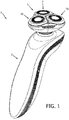
- Figs. 1-4 show the shaving device 1 based on the first embodiment of the shaving head.
- Fig. 1 shows that the shaving device 1 comprises the shaving device main body 2 and the shaving head 3 being connected thereto.
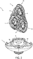
- Fig. 2 shows that the shaving head 3 can be taken apart into the shaving head driving body 4 and the shaving head cutting body 5.
- the shaving head cutting body 5 has the frame 8, to which the three identical first cutting units 7, 7A, 7B of the shaving head 3 are connected.
- the shaving head driving body 4 has the three driving shafts 6, 6A, 6B for driving the three internal cutting members 22 of the three cutting units 7, 7A, 7B, respectively.
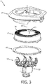
- Fig. 3 shows that the first cutting unit 7 comprises the external cutting member 11 and the internal cutting member 12.
- the shown skin supporting member 14 of the shaving head cutting body 5 is suspended relative to the frame 8 of the shaving head cutting body 5, while at the same time the external cutting member 11 is connected relative to the skin supporting member 14 via the shown fixation ring 15.
- the external cutting member 11 has the shaving surface 16, which is interrupted by an apertured structure for allowing hairs to pass.
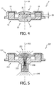
- Fig. 4 shows the first cutting unit 7 in the interconnected condition of the external and internal cutting members 11, 12.
- the first central portion 21 of the external cutting member 11 comprises the first snap connection structure 31, while the second central portion 22 of the internal cutting member 12 comprises the second snap connection structure 32.
- the first snap connection structure 31 and the second snap connection structure 32 provide radial bearing support, i.e. bearing support in a radial direction relative to the rotation axis 10, for the rotative movement of the internal cutting member 12 relative to the external cutting member 11 about the rotation axis 10.
- Fig. 4 furthermore illustrates that the first snap connection structure 31 and the second snap connection structure 32 allow the abovementioned amount of play 20 in respect of translational movement of the internal cutting member 12 relative to the external cutting member 11 in a direction parallel to the rotation axis 10.
- the first snap connection structure 31 is a bearing stud 31, whose free end has a locally increased diameter
- the second snap connection structure 32 is a cylindrical recess 32, whose entry opening has a locally decreased diameter, while allowing the said play 20.
- the bearing surfaces of the rotative movement between the external and internal cutting members may, amongst others, be formed with such a locally decreased diameter surface of the entry opening of the cylindrical recess and/or such a locally increased diameter surface of the free end of the bearing stud and/or with any other surfaces of the external and internal cutting members.
- first snap connection structure and/or the second snap connection structure may for example be made of a resilient material.
- the structure defining the cylindrical recess 32 may for example be made of a resilient plastic material.
- the snap connection is preferably designed in such a manner that said holding forces in the first place are sufficient for the internal cutting members to remain in the external cutting members at least when the shaving head 3 is being taken apart from the situation as shown in Fig. 1 into the situation of Fig. 2 .
- said holding forces should preferably be sufficient to carry several times the mass of an internal cutting member (which usually is not much more than 1 g).
- the snap connection is preferably designed in such a manner that in the situation of Fig. 2 the manual pulling force required to remove an internal cutting member from an external cutting member will be in the order of magnitude of less than about 20 gf.
- FIG. 5 shows the second cutting unit 207 for use in the abovementioned second embodiment of a shaving head according to the invention.
- the second cutting unit 207 comprises the external cutting member 211 and the internal cutting member 212. It is seen that the first central portion 221 and the second central portion 222 are mutually co-operating portions providing radial bearing support for the rotative movement about the rotation axis 210.
- the magnet 230 is associated with, and arranged in, the second central portion 222 for providing the abovementioned magnetic attraction between the first central portion 221 and the second central portion 222.
- the first central portion 221 comprises magnetizable material.
- the magnetic axis of the magnet 230 has been indicated by means of the depicted two-way arrow, while the corresponding magnetic field of the magnet 230 has been indicated by means of the magnetic field lines 240.
- the magnet 230 is placed so as to have its magnetic axis aligned with the rotation axis 210.
- the magnetic field thus is maximally coupled with the bearing stud of the first central portion 221.
- such a bearing stud contains a relatively large proportion of the material of the external cutting member, as a result of which the placement of the magnet 230, as shown, is very favourable.
- a practical shape for the magnet used is a cylindrical shape having a diameter of between 2 and 3 mm and a height of between 1 and 3 mm.
- the force-density requirements are modest, so a relatively low-cost grade of neodymium magnet is already sufficient.
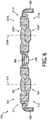
- FIG. 6 shows a cutting body 305 of the abovementioned third embodiment of a shaving head according to the invention.
- This shaving head cutting body 305 comprises the two third cutting units 307 and 307A, which are connected to the frame 308 of the shaving head cutting body 305.
- the third cutting unit 307 comprises the external cutting member 311 and the internal cutting member 312. It is seen that the first central portion 321 and the second central portion 322 are mutually co-operating portions providing radial bearing support for the rotative movement about the rotation axis 310.
- the third cutting unit 307A comprises the external cutting member 311A and the internal cutting member 312A, while the first central portion 321A and the second central portion 322A are mutually co-operating portions providing radial bearing support for the rotative movement about the rotation axis 310A.
- the magnet 330 is associated with the shaving head and arranged in the shaving head so as to be remote from the first central portions 321 and 321A and from the second central portions 322 and 322A for magnetically influencing these first central portions and these second central portions for providing the abovementioned magnetic attraction between the first central portion 321 and the second central portion 322, as well as for simultaneously providing the abovementioned magnetic attraction between the first central portion 321A and the second central portion 322A.
- each one of the first central portions 321, 321A and the second central portions 322, 322A comprises magnetizable material.
Landscapes
- Life Sciences & Earth Sciences (AREA)
- Forests & Forestry (AREA)
- Engineering & Computer Science (AREA)
- Mechanical Engineering (AREA)
- Dry Shavers And Clippers (AREA)
Claims (14)
- Unité de coupe (7, 7A, 7B ; 207) à utiliser dans un dispositif de rasage (1) pour raser des cheveux, ladite unité de coupe comprenant :- un élément de coupe externe (11 ; 211) comprenant une surface de rasage (16), qui est interrompu par une structure à ouvertures pour permettre aux cheveux de passer ; et- un élément de coupe interne (12 ; 212), qui peut être entraîné dans un mouvement rotatif par rapport à l'élément de coupe externe autour d'un axe de rotation (10 ; 210) et le long de ladite structure à ouvertures dans la surface de rasage de l'élément de coupe externe pour couper les cheveux passant à travers ladite structure à ouvertures ;et dans lequel :- l'élément de coupe externe et l'élément de coupe interne ont :- un état interconnecté, dans lequel l'élément de coupe externe et l'élément de coupe interne sont mutuellement interconnectés pour la mise en oeuvre de l'unité de coupe, et- un état déconnecté, dans lequel l'élément de coupe externe et l'élément de coupe interne sont mutuellement déconnectés pour sortir l'élément de coupe interne de l'élément de coupe externe pour nettoyer l'unité de coupe ;- l'élément de coupe externe a une première portion centrale (21 ; 221) et l'élément de coupe interne a une seconde portion centrale (22 ; 222), dans lequel dans ledit état interconnecté ledit axe de rotation est une ligne centrale de la première portion centrale aussi bien que de la seconde portion centrale ;- dans ledit état interconnecté une force de maintien empêche l'élément de coupe externe et l'élément de coupe interne de s'écarter dans l'état déconnecté ;- ladite force de maintien est au moins exercée par la première portion centrale sur la seconde portion centrale, et/ou vice versa ; et- ledit état déconnecté peut être obtenu à partir dudit état interconnecté en déplaçant manuellement l'élément de coupe externe et l'élément de coupe interne à l'écart l'un de l'autre dans une direction parallèle audit axe de rotation au moyen d'une action de force manuelle surmontant ladite force de maintien.
- Unité de coupe (7, 7A, 7B ; 207) selon la revendication 1, dans laquelle dans ledit état interconnecté la première portion centrale (21 ; 221) et la seconde portion centrale (22 ; 222) sont des portions mutuellement coopérantes fournissant un support de palier radial pour ledit mouvement rotatif.
- Unité de coupe (7, 7A, 7B) selon la revendication 1 ou 2, dans laquelle la première portion centrale (21) comprend une première structure de connexion par encliquetage (31) et la seconde portion centrale (22) comprend une seconde structure de connexion par encliquetage (32), et dans laquelle la première structure de connexion par encliquetage et la seconde structure de connexion par encliquetage coopèrent mutuellement pour fournir au moins une partie de ladite force de maintien au moyen de ladite connexion par encliquetage.
- Unité de coupe (7, 7A, 7B) selon la revendication 3, dans laquelle dans ledit état interconnecté la première structure de connexion par encliquetage (31) et la seconde structure de connexion par encliquetage (32) fournissent un support de palier radial pour ledit mouvement rotatif.
- Unité de coupe (7, 7A, 7B) selon la revendication 3 ou 4, dans laquelle dans ledit état interconnecté la première structure de connexion par encliquetage (31) et la seconde structure de connexion par encliquetage (32) autorisent une quantité de jeu (20) d'au moins 0,2 millimètre et de préférence au moins 0,4 millimètre, en ce qui concerne un mouvement de translation de l'élément de coupe interne (12) par rapport à l'élément de coupe externe (11) dans une direction parallèle audit axe de rotation (10).
- Unité de coupe (207) selon l'une quelconque des revendications précédentes, comprenant en outre un système d'aimant (230) configuré, agencé et efficace pour fournir une attraction magnétique au moins entre la première portion centrale (221) et la seconde portion centrale (222) pour fournir au moins une partie de ladite force de maintien.
- Unité de coupe selon la revendication 6, dans laquelle ledit système d'aimant comprend un aimant associé à et agencé dans et/ou au niveau de la première portion centrale pour fournir ladite attraction magnétique.
- Unité de coupe selon la revendication 7, dans laquelle dans ledit état interconnecté un axe magnétique dudit aimant associé à la première portion centrale est aligné sur ledit axe de rotation.
- Unité de coupe (207) selon l'une quelconque des revendications 6 à 8, dans laquelle ledit système d'aimant comprend un aimant (230) associé à et agencé dans et/ou au niveau de la seconde portion centrale (222) pour fournir ladite attraction magnétique.
- Unité de coupe (207) selon la revendication 9, dans laquelle dans ledit état interconnecté un axe magnétique dudit aimant (230) associé à la seconde portion centrale (222) est aligné sur ledit axe de rotation (210).
- Tête de rasage (3) à utiliser dans un dispositif de rasage (1) pour raser des cheveux, ladite tête de rasage comprenant au moins une unité de coupe (7, 7A, 7B ; 207) selon l'une quelconque des revendications 1 à 10.
- Tête de rasage à utiliser dans un dispositif de rasage pour raser des cheveux, ladite tête de rasage comprenant au moins une unité de coupe (307, 307A), dans laquelle chaque unité de coupe comprend :- un élément de coupe externe (311, 311A) comprenant une surface de rasage, qui est interrompue par une structure à ouvertures pour permettre aux cheveux de passer ; et- un élément de coupe interne (312, 312A), qui peut être entraîné dans un mouvement rotatif par rapport à l'élément de coupe externe autour d'un axe de rotation (310, 310A) et le long de ladite structure à ouvertures dans la surface de rasage de l'élément de coupe externe pour couper les cheveux passant à travers ladite structure à ouvertures ;et dans lequel :- l'élément de coupe externe et l'élément de coupe interne ont :- un état interconnecté, dans lequel l'élément de coupe externe et l'élément de coupe interne sont mutuellement interconnectés pour la mise en oeuvre de la tête de rasage, et- un état déconnecté, dans lequel l'élément de coupe externe et l'élément de coupe interne sont mutuellement déconnectés pour sortir au moins l'élément de coupe interne de la tête de rasage pour le nettoyage de l'unité de coupe ;- l'élément de coupe externe a une première portion centrale (321, 321A) et l'élément de coupe interne a une seconde portion centrale (322, 322A), dans lequel dans ledit état interconnecté ledit axe de rotation est une ligne centrale de la première portion centrale aussi bien que de la seconde portion centrale ;- dans ledit état interconnecté une force de maintien empêche l'élément de coupe externe et l'élément de coupe interne de s'écarter dans l'état déconnecté ;- ladite force de maintien est au moins exercée par la première portion centrale sur la seconde portion centrale, et/ou vice versa ; et- ledit état déconnecté peut être obtenu à partir dudit état interconnecté en déplaçant manuellement l'élément de coupe externe et l'élément de coupe interne à l'écart l'un de l'autre dans une direction parallèle audit axe de rotation au moyen d'une action de force manuelle surmontant ladite force de maintien,dans lequel la tête de rasage comprend en outre un système d'aimant configuré, agencé et efficace pour fournir une attraction magnétique au moins entre la première portion centrale et la seconde portion centrale pour fournir au moins une partie de ladite force de maintien, et dans lequel ledit système d'aimant comprend un aimant (330) associé à la tête de rasage et agencé dans et/ou au niveau de la tête de rasage afin d'être distant de la première portion centrale (321, 321A) et de la seconde portion centrale (322, 322A) pour magnétiquement influencer la première portion centrale et la seconde portion centrale pour fournir ladite attraction magnétique.
- Tête de rasage selon la revendication 12, dans laquelle ladite au moins une unité de coupe est une multiplicité d'unités de coupe respectives (307, 307A), et dans laquelle la tête de rasage comprend un système d'aimant configuré, agencé et efficace pour fournir une attraction magnétique au moins entre la première portion centrale (321, 321A) et la seconde portion centrale (322, 322A) de chaque unité de coupe respective pour fournir au moins une partie de ladite force de maintien, et dans laquelle ledit système d'aimant comprend un aimant (330) associé à la tête de rasage et agencé dans et/ou au niveau de la tête de rasage afin d'être distant de la première portion centrale (321, 321A) et de la seconde portion centrale (322, 322A) de chaque unité de coupe respective (307, 307A) pour simultanément influencer magnétiquement lesdites première et seconde portions centrales de chaque unité de coupe respective pour fournir ladite attraction magnétique entre les première et seconde portions centrales de chaque unité de coupe respective (307, 307A).
- Dispositif de rasage pour raser des cheveux, comprenant :- un corps principal de dispositif de rasage (2) qui est destiné à être pris par un utilisateur du dispositif de rasage (1) et qui sert à loger divers éléments du dispositif de rasage ; et- une tête de rasage (3) selon l'une quelconque des revendications 11 à 13, la tête de rasage étant connectée ou pouvant être connectée au corps principal de dispositif de rasage pour la mise en oeuvre du dispositif de rasage.
Applications Claiming Priority (2)
| Application Number | Priority Date | Filing Date | Title |
|---|---|---|---|
| EP15168613 | 2015-05-21 | ||
| PCT/EP2016/060116 WO2016184693A1 (fr) | 2015-05-21 | 2016-05-05 | Unité de coupe améliorée et tête de rasage d'un dispositif de rasage |
Publications (2)
| Publication Number | Publication Date |
|---|---|
| EP3297796A1 EP3297796A1 (fr) | 2018-03-28 |
| EP3297796B1 true EP3297796B1 (fr) | 2018-12-19 |
Family
ID=53188961
Family Applications (1)
| Application Number | Title | Priority Date | Filing Date |
|---|---|---|---|
| EP16720442.9A Active EP3297796B1 (fr) | 2015-05-21 | 2016-05-05 | Tête de rasage améliorée d'un dispositif de rasage |
Country Status (8)
| Country | Link |
|---|---|
| US (2) | US10836057B2 (fr) |
| EP (1) | EP3297796B1 (fr) |
| JP (1) | JP6517369B2 (fr) |
| CN (1) | CN107666991B (fr) |
| BR (1) | BR112017024476A2 (fr) |
| RU (1) | RU2710400C2 (fr) |
| TR (1) | TR201902740T4 (fr) |
| WO (1) | WO2016184693A1 (fr) |
Families Citing this family (10)
| Publication number | Priority date | Publication date | Assignee | Title |
|---|---|---|---|---|
| WO2020037554A1 (fr) * | 2018-08-22 | 2020-02-27 | 舒可士(深圳)科技有限公司 | Structure de raccordement de tête de coupe, tête de coupe, manche et rasoir |
| EP3647002A1 (fr) * | 2018-11-05 | 2020-05-06 | Koninklijke Philips N.V. | Unité de coupe pour un appareil de rasage comprenant une structure de ventilateur de transport de poils |
| EP3659759A1 (fr) * | 2018-11-28 | 2020-06-03 | Koninklijke Philips N.V. | Unité de coupe de cheveux dotée d'une prévention du blocage de la lame |
| CN109500842A (zh) * | 2018-12-04 | 2019-03-22 | 中山市小石陶瓷刀片有限公司 | 一种电动旋转式胡须刀的刀头与刀网的连接结构 |
| EP3738730A1 (fr) * | 2019-05-14 | 2020-11-18 | Koninklijke Philips N.V. | Appareil de rasage avec commande de réglage d'un paramètre de fonctionnement |
| CN111941472A (zh) * | 2019-05-17 | 2020-11-17 | 焕醒科技(杭州)有限公司 | 一种电动剃须刀用传动机构及其电动剃须刀 |
| WO2021003213A1 (fr) | 2019-07-01 | 2021-01-07 | Spectrum Brands, Inc. | Appareil de soins électrique comprenant un système de couplage magnétique |
| CN111390980B (zh) * | 2020-04-21 | 2024-10-18 | 陈光喜 | 护理用品磁复位结构 |
| JP1708250S (ja) * | 2020-04-29 | 2022-02-24 | シェーバー用ハンドル | |
| CN116352772A (zh) * | 2021-12-28 | 2023-06-30 | 宁波爱听科技有限公司 | 一种刀头组件及具有该刀头组件的剃须刀 |
Family Cites Families (31)
| Publication number | Priority date | Publication date | Assignee | Title |
|---|---|---|---|---|
| US3116551A (en) * | 1960-09-07 | 1964-01-07 | Nicholas T Anton | Rotary shaver |
| NL296894A (fr) * | 1963-08-20 | |||
| US4038748A (en) | 1972-03-27 | 1977-08-02 | Tyler Tracy B | Rotary dry shaver with tiltable shear plates |
| US4077120A (en) * | 1972-07-14 | 1978-03-07 | Bissell, Inc. | Dry shaver with floating peripherally supported shear plate |
| US4089110A (en) * | 1976-03-08 | 1978-05-16 | Rasco Darius K | Shaving means |
| JPS6041907Y2 (ja) * | 1980-03-05 | 1985-12-20 | 松下電工株式会社 | 回転式電気カミソリ |
| JP2527311B2 (ja) * | 1986-09-22 | 1996-08-21 | 松下電工株式会社 | 回転式電気かみそりの刃 |
| JP2519759B2 (ja) * | 1987-11-11 | 1996-07-31 | 株式会社東芝 | 回転式切断器 |
| BE1007711A3 (nl) * | 1993-11-05 | 1995-10-03 | Koninkl Philips Electronics Nv | Scheerapparaat. |
| US6032365A (en) * | 1997-02-24 | 2000-03-07 | James L. Hodges | Slotted rotary shaver |
| JPH114980A (ja) | 1997-06-17 | 1999-01-12 | Izumi Prod Co | 電気かみそり |
| DE69908527T2 (de) * | 1998-03-27 | 2004-05-13 | Koninklijke Philips Electronics N.V. | Rasiergerät |
| JP4519219B2 (ja) * | 1999-06-21 | 2010-08-04 | 株式会社泉精器製作所 | 回転式電気かみそり |
| US6769179B2 (en) * | 2000-07-06 | 2004-08-03 | Teizoh Satoh | Shaver |
| JP3896506B2 (ja) * | 2000-07-06 | 2007-03-22 | 貞三 佐藤 | 電気剃刀 |
| WO2003011537A1 (fr) * | 2001-07-30 | 2003-02-13 | Koninklijke Philips Electronics N.V. | Raccord pour element de coupe interne d'un rasoir rotatif |
| JP4528764B2 (ja) * | 2003-01-20 | 2010-08-18 | コーニンクレッカ フィリップス エレクトロニクス エヌ ヴィ | ひげ剃り器 |
| JP2005312523A (ja) * | 2004-04-27 | 2005-11-10 | Izumi Products Co | 回転式電気かみそり |
| EP1761366B1 (fr) * | 2004-06-21 | 2010-09-15 | Koninklijke Philips Electronics N.V. | Rasoir |
| JP4490219B2 (ja) | 2004-09-21 | 2010-06-23 | 株式会社泉精器製作所 | 回転式電気かみそり |
| ES2362497T3 (es) * | 2004-12-22 | 2011-07-06 | Koninklijke Philips Electronics N.V. | Afeitadoras rotatorias, con accionamiento y estructura de soporte para los cabezales de afeitado mejorados. |
| JP4756908B2 (ja) * | 2005-05-18 | 2011-08-24 | 株式会社泉精器製作所 | ロータリー式電気かみそり |
| EP2015904B1 (fr) * | 2006-05-01 | 2010-02-10 | Koninklijke Philips Electronics N.V. | Dispositif de coupe et appareil pour couper les cheveux |
| JP5207457B2 (ja) * | 2008-06-27 | 2013-06-12 | 株式会社泉精器製作所 | 回転式電気かみそり |
| JP5339338B2 (ja) * | 2008-06-27 | 2013-11-13 | 株式会社泉精器製作所 | 回転式電気かみそり |
| CN101474797A (zh) | 2008-12-08 | 2009-07-08 | 超人集团有限公司 | 剃须刀装置 |
| US9027251B2 (en) * | 2009-04-29 | 2015-05-12 | Spectrum Brands, Inc. | Rotary electric shaver |
| JP6034193B2 (ja) * | 2009-11-09 | 2016-11-30 | コーニンクレッカ フィリップス エヌ ヴェKoninklijke Philips N.V. | シェービングヘッドユニット及び斯かるシェービングヘッドユニットを備えたシェーバ |
| CN102284963A (zh) | 2011-07-15 | 2011-12-21 | 海宁市新艺机电有限公司 | 一种旋转式剃须刀刀片及设有该刀片的剃须刀刀头 |
| JP2014117381A (ja) | 2012-12-14 | 2014-06-30 | Izumi Products Co | ロータリー式電気かみそり |
| CN203495989U (zh) | 2013-09-17 | 2014-03-26 | 虞雪辉 | 新型剃须刀刀头结构 |
-
2016
- 2016-05-05 CN CN201680029259.6A patent/CN107666991B/zh active Active
- 2016-05-05 WO PCT/EP2016/060116 patent/WO2016184693A1/fr not_active Ceased
- 2016-05-05 RU RU2017144508A patent/RU2710400C2/ru active
- 2016-05-05 TR TR2019/02740T patent/TR201902740T4/tr unknown
- 2016-05-05 EP EP16720442.9A patent/EP3297796B1/fr active Active
- 2016-05-05 US US15/572,183 patent/US10836057B2/en active Active
- 2016-05-05 JP JP2017557370A patent/JP6517369B2/ja not_active Expired - Fee Related
- 2016-05-05 BR BR112017024476A patent/BR112017024476A2/pt active Search and Examination
-
2020
- 2020-10-14 US US17/069,914 patent/US11597108B2/en active Active
Non-Patent Citations (1)
| Title |
|---|
| None * |
Also Published As
| Publication number | Publication date |
|---|---|
| US20180147738A1 (en) | 2018-05-31 |
| CN107666991A (zh) | 2018-02-06 |
| BR112017024476A2 (pt) | 2018-12-11 |
| CN107666991B (zh) | 2019-08-16 |
| JP2018514323A (ja) | 2018-06-07 |
| US20210023728A1 (en) | 2021-01-28 |
| US10836057B2 (en) | 2020-11-17 |
| JP6517369B2 (ja) | 2019-05-22 |
| RU2710400C2 (ru) | 2019-12-26 |
| TR201902740T4 (tr) | 2019-03-21 |
| EP3297796A1 (fr) | 2018-03-28 |
| US11597108B2 (en) | 2023-03-07 |
| WO2016184693A1 (fr) | 2016-11-24 |
| RU2017144508A (ru) | 2019-06-24 |
| RU2017144508A3 (fr) | 2019-10-30 |
Similar Documents
| Publication | Publication Date | Title |
|---|---|---|
| US11597108B2 (en) | Cutting unit and shaving head of a shaving device | |
| US12528215B2 (en) | Shaving device | |
| US20250353199A1 (en) | Shaving Device | |
| CN106660223B (zh) | 可拆卸地连接剃须刀与刀架的手柄 | |
| US8414531B2 (en) | Handheld device for the local puncturing of a human or an animal skin, drive unit, needle unit and method for coupling | |
| US9707688B2 (en) | Shaver | |
| KR101891643B1 (ko) | 다발형 모발 이식기 | |
| CN109069811A (zh) | 可抛式文身针筒 | |
| JP4490219B2 (ja) | 回転式電気かみそり | |
| EP2221000A1 (fr) | Dispositif de perforation | |
| EP3110020A1 (fr) | Dispositif électronique comprenant un plateau à cartes | |
| TW201440641A (zh) | 連接裝置 | |
| JP2024543354A (ja) | ハンドヘルドパーソナルケアデバイスのメインハウジングと機能的アタッチメントとの結合及び分離 | |
| JP2015147271A (ja) | ステープル針用リムーバ | |
| JP2010213977A (ja) | シリンジロック機構 | |
| EP3488981A1 (fr) | Unité de rasage ayant une structure de retenue | |
| CN109807948B (zh) | 具有保持结构的剃刮单元 | |
| CN109676334A (zh) | 组装装置 | |
| WO2021026244A1 (fr) | Porte-embout magnétique à manchon de guidage à rétraction automatique | |
| EP3769922A1 (fr) | Ensemble de couplage destiné à être utilisé dans un appareil de soins personnels | |
| EP3511048A1 (fr) | Appareil de rouleau de disque à aiguilles | |
| US10966490B2 (en) | Female button and combination of female button and male button | |
| EP2610386A2 (fr) | Dispositif d'enfilage d'aiguille et son unité de fonctionnement | |
| KR20180088950A (ko) | 모발 이식 장치 | |
| KR101340324B1 (ko) | 채혈침 조립체 |
Legal Events
| Date | Code | Title | Description |
|---|---|---|---|
| STAA | Information on the status of an ep patent application or granted ep patent |
Free format text: STATUS: THE INTERNATIONAL PUBLICATION HAS BEEN MADE |
|
| PUAI | Public reference made under article 153(3) epc to a published international application that has entered the european phase |
Free format text: ORIGINAL CODE: 0009012 |
|
| STAA | Information on the status of an ep patent application or granted ep patent |
Free format text: STATUS: REQUEST FOR EXAMINATION WAS MADE |
|
| 17P | Request for examination filed |
Effective date: 20171221 |
|
| AK | Designated contracting states |
Kind code of ref document: A1 Designated state(s): AL AT BE BG CH CY CZ DE DK EE ES FI FR GB GR HR HU IE IS IT LI LT LU LV MC MK MT NL NO PL PT RO RS SE SI SK SM TR |
|
| AX | Request for extension of the european patent |
Extension state: BA ME |
|
| GRAP | Despatch of communication of intention to grant a patent |
Free format text: ORIGINAL CODE: EPIDOSNIGR1 |
|
| STAA | Information on the status of an ep patent application or granted ep patent |
Free format text: STATUS: GRANT OF PATENT IS INTENDED |
|
| DAX | Request for extension of the european patent (deleted) | ||
| INTG | Intention to grant announced |
Effective date: 20180705 |
|
| DAV | Request for validation of the european patent (deleted) | ||
| GRAS | Grant fee paid |
Free format text: ORIGINAL CODE: EPIDOSNIGR3 |
|
| GRAA | (expected) grant |
Free format text: ORIGINAL CODE: 0009210 |
|
| STAA | Information on the status of an ep patent application or granted ep patent |
Free format text: STATUS: THE PATENT HAS BEEN GRANTED |
|
| AK | Designated contracting states |
Kind code of ref document: B1 Designated state(s): AL AT BE BG CH CY CZ DE DK EE ES FI FR GB GR HR HU IE IS IT LI LT LU LV MC MK MT NL NO PL PT RO RS SE SI SK SM TR |
|
| REG | Reference to a national code |
Ref country code: GB Ref legal event code: FG4D |
|
| REG | Reference to a national code |
Ref country code: CH Ref legal event code: EP |
|
| REG | Reference to a national code |
Ref country code: IE Ref legal event code: FG4D |
|
| REG | Reference to a national code |
Ref country code: DE Ref legal event code: R096 Ref document number: 602016008493 Country of ref document: DE |
|
| REG | Reference to a national code |
Ref country code: AT Ref legal event code: REF Ref document number: 1078187 Country of ref document: AT Kind code of ref document: T Effective date: 20190115 |
|
| REG | Reference to a national code |
Ref country code: NL Ref legal event code: FP |
|
| PG25 | Lapsed in a contracting state [announced via postgrant information from national office to epo] |
Ref country code: HR Free format text: LAPSE BECAUSE OF FAILURE TO SUBMIT A TRANSLATION OF THE DESCRIPTION OR TO PAY THE FEE WITHIN THE PRESCRIBED TIME-LIMIT Effective date: 20181219 Ref country code: LV Free format text: LAPSE BECAUSE OF FAILURE TO SUBMIT A TRANSLATION OF THE DESCRIPTION OR TO PAY THE FEE WITHIN THE PRESCRIBED TIME-LIMIT Effective date: 20181219 Ref country code: NO Free format text: LAPSE BECAUSE OF FAILURE TO SUBMIT A TRANSLATION OF THE DESCRIPTION OR TO PAY THE FEE WITHIN THE PRESCRIBED TIME-LIMIT Effective date: 20190319 Ref country code: FI Free format text: LAPSE BECAUSE OF FAILURE TO SUBMIT A TRANSLATION OF THE DESCRIPTION OR TO PAY THE FEE WITHIN THE PRESCRIBED TIME-LIMIT Effective date: 20181219 Ref country code: BG Free format text: LAPSE BECAUSE OF FAILURE TO SUBMIT A TRANSLATION OF THE DESCRIPTION OR TO PAY THE FEE WITHIN THE PRESCRIBED TIME-LIMIT Effective date: 20190319 Ref country code: LT Free format text: LAPSE BECAUSE OF FAILURE TO SUBMIT A TRANSLATION OF THE DESCRIPTION OR TO PAY THE FEE WITHIN THE PRESCRIBED TIME-LIMIT Effective date: 20181219 |
|
| REG | Reference to a national code |
Ref country code: LT Ref legal event code: MG4D |
|
| REG | Reference to a national code |
Ref country code: AT Ref legal event code: MK05 Ref document number: 1078187 Country of ref document: AT Kind code of ref document: T Effective date: 20181219 |
|
| PG25 | Lapsed in a contracting state [announced via postgrant information from national office to epo] |
Ref country code: GR Free format text: LAPSE BECAUSE OF FAILURE TO SUBMIT A TRANSLATION OF THE DESCRIPTION OR TO PAY THE FEE WITHIN THE PRESCRIBED TIME-LIMIT Effective date: 20190320 Ref country code: AL Free format text: LAPSE BECAUSE OF FAILURE TO SUBMIT A TRANSLATION OF THE DESCRIPTION OR TO PAY THE FEE WITHIN THE PRESCRIBED TIME-LIMIT Effective date: 20181219 Ref country code: SE Free format text: LAPSE BECAUSE OF FAILURE TO SUBMIT A TRANSLATION OF THE DESCRIPTION OR TO PAY THE FEE WITHIN THE PRESCRIBED TIME-LIMIT Effective date: 20181219 Ref country code: RS Free format text: LAPSE BECAUSE OF FAILURE TO SUBMIT A TRANSLATION OF THE DESCRIPTION OR TO PAY THE FEE WITHIN THE PRESCRIBED TIME-LIMIT Effective date: 20181219 |
|
| PG25 | Lapsed in a contracting state [announced via postgrant information from national office to epo] |
Ref country code: PL Free format text: LAPSE BECAUSE OF FAILURE TO SUBMIT A TRANSLATION OF THE DESCRIPTION OR TO PAY THE FEE WITHIN THE PRESCRIBED TIME-LIMIT Effective date: 20181219 Ref country code: ES Free format text: LAPSE BECAUSE OF FAILURE TO SUBMIT A TRANSLATION OF THE DESCRIPTION OR TO PAY THE FEE WITHIN THE PRESCRIBED TIME-LIMIT Effective date: 20181219 Ref country code: CZ Free format text: LAPSE BECAUSE OF FAILURE TO SUBMIT A TRANSLATION OF THE DESCRIPTION OR TO PAY THE FEE WITHIN THE PRESCRIBED TIME-LIMIT Effective date: 20181219 Ref country code: PT Free format text: LAPSE BECAUSE OF FAILURE TO SUBMIT A TRANSLATION OF THE DESCRIPTION OR TO PAY THE FEE WITHIN THE PRESCRIBED TIME-LIMIT Effective date: 20190419 Ref country code: IT Free format text: LAPSE BECAUSE OF FAILURE TO SUBMIT A TRANSLATION OF THE DESCRIPTION OR TO PAY THE FEE WITHIN THE PRESCRIBED TIME-LIMIT Effective date: 20181219 |
|
| PG25 | Lapsed in a contracting state [announced via postgrant information from national office to epo] |
Ref country code: SK Free format text: LAPSE BECAUSE OF FAILURE TO SUBMIT A TRANSLATION OF THE DESCRIPTION OR TO PAY THE FEE WITHIN THE PRESCRIBED TIME-LIMIT Effective date: 20181219 Ref country code: SM Free format text: LAPSE BECAUSE OF FAILURE TO SUBMIT A TRANSLATION OF THE DESCRIPTION OR TO PAY THE FEE WITHIN THE PRESCRIBED TIME-LIMIT Effective date: 20181219 Ref country code: EE Free format text: LAPSE BECAUSE OF FAILURE TO SUBMIT A TRANSLATION OF THE DESCRIPTION OR TO PAY THE FEE WITHIN THE PRESCRIBED TIME-LIMIT Effective date: 20181219 Ref country code: IS Free format text: LAPSE BECAUSE OF FAILURE TO SUBMIT A TRANSLATION OF THE DESCRIPTION OR TO PAY THE FEE WITHIN THE PRESCRIBED TIME-LIMIT Effective date: 20190419 Ref country code: RO Free format text: LAPSE BECAUSE OF FAILURE TO SUBMIT A TRANSLATION OF THE DESCRIPTION OR TO PAY THE FEE WITHIN THE PRESCRIBED TIME-LIMIT Effective date: 20181219 |
|
| REG | Reference to a national code |
Ref country code: DE Ref legal event code: R097 Ref document number: 602016008493 Country of ref document: DE |
|
| PLBE | No opposition filed within time limit |
Free format text: ORIGINAL CODE: 0009261 |
|
| STAA | Information on the status of an ep patent application or granted ep patent |
Free format text: STATUS: NO OPPOSITION FILED WITHIN TIME LIMIT |
|
| PG25 | Lapsed in a contracting state [announced via postgrant information from national office to epo] |
Ref country code: AT Free format text: LAPSE BECAUSE OF FAILURE TO SUBMIT A TRANSLATION OF THE DESCRIPTION OR TO PAY THE FEE WITHIN THE PRESCRIBED TIME-LIMIT Effective date: 20181219 Ref country code: DK Free format text: LAPSE BECAUSE OF FAILURE TO SUBMIT A TRANSLATION OF THE DESCRIPTION OR TO PAY THE FEE WITHIN THE PRESCRIBED TIME-LIMIT Effective date: 20181219 |
|
| 26N | No opposition filed |
Effective date: 20190920 |
|
| REG | Reference to a national code |
Ref country code: CH Ref legal event code: PL |
|
| PG25 | Lapsed in a contracting state [announced via postgrant information from national office to epo] |
Ref country code: MC Free format text: LAPSE BECAUSE OF FAILURE TO SUBMIT A TRANSLATION OF THE DESCRIPTION OR TO PAY THE FEE WITHIN THE PRESCRIBED TIME-LIMIT Effective date: 20181219 Ref country code: CH Free format text: LAPSE BECAUSE OF NON-PAYMENT OF DUE FEES Effective date: 20190531 Ref country code: LI Free format text: LAPSE BECAUSE OF NON-PAYMENT OF DUE FEES Effective date: 20190531 |
|
| PG25 | Lapsed in a contracting state [announced via postgrant information from national office to epo] |
Ref country code: SI Free format text: LAPSE BECAUSE OF FAILURE TO SUBMIT A TRANSLATION OF THE DESCRIPTION OR TO PAY THE FEE WITHIN THE PRESCRIBED TIME-LIMIT Effective date: 20181219 Ref country code: LU Free format text: LAPSE BECAUSE OF NON-PAYMENT OF DUE FEES Effective date: 20190505 |
|
| PG25 | Lapsed in a contracting state [announced via postgrant information from national office to epo] |
Ref country code: IE Free format text: LAPSE BECAUSE OF NON-PAYMENT OF DUE FEES Effective date: 20190505 |
|
| PGFP | Annual fee paid to national office [announced via postgrant information from national office to epo] |
Ref country code: TR Payment date: 20200429 Year of fee payment: 5 |
|
| PG25 | Lapsed in a contracting state [announced via postgrant information from national office to epo] |
Ref country code: CY Free format text: LAPSE BECAUSE OF FAILURE TO SUBMIT A TRANSLATION OF THE DESCRIPTION OR TO PAY THE FEE WITHIN THE PRESCRIBED TIME-LIMIT Effective date: 20181219 |
|
| PG25 | Lapsed in a contracting state [announced via postgrant information from national office to epo] |
Ref country code: MT Free format text: LAPSE BECAUSE OF FAILURE TO SUBMIT A TRANSLATION OF THE DESCRIPTION OR TO PAY THE FEE WITHIN THE PRESCRIBED TIME-LIMIT Effective date: 20181219 Ref country code: HU Free format text: LAPSE BECAUSE OF FAILURE TO SUBMIT A TRANSLATION OF THE DESCRIPTION OR TO PAY THE FEE WITHIN THE PRESCRIBED TIME-LIMIT; INVALID AB INITIO Effective date: 20160505 |
|
| PGFP | Annual fee paid to national office [announced via postgrant information from national office to epo] |
Ref country code: NL Payment date: 20210526 Year of fee payment: 6 |
|
| PGFP | Annual fee paid to national office [announced via postgrant information from national office to epo] |
Ref country code: BE Payment date: 20210527 Year of fee payment: 6 |
|
| PG25 | Lapsed in a contracting state [announced via postgrant information from national office to epo] |
Ref country code: MK Free format text: LAPSE BECAUSE OF FAILURE TO SUBMIT A TRANSLATION OF THE DESCRIPTION OR TO PAY THE FEE WITHIN THE PRESCRIBED TIME-LIMIT Effective date: 20181219 |
|
| REG | Reference to a national code |
Ref country code: NL Ref legal event code: MM Effective date: 20220601 |
|
| REG | Reference to a national code |
Ref country code: BE Ref legal event code: MM Effective date: 20220531 |
|
| PG25 | Lapsed in a contracting state [announced via postgrant information from national office to epo] |
Ref country code: BE Free format text: LAPSE BECAUSE OF NON-PAYMENT OF DUE FEES Effective date: 20220531 |
|
| PG25 | Lapsed in a contracting state [announced via postgrant information from national office to epo] |
Ref country code: NL Free format text: LAPSE BECAUSE OF NON-PAYMENT OF DUE FEES Effective date: 20220601 |
|
| PG25 | Lapsed in a contracting state [announced via postgrant information from national office to epo] |
Ref country code: TR Free format text: LAPSE BECAUSE OF NON-PAYMENT OF DUE FEES Effective date: 20210505 |
|
| PGFP | Annual fee paid to national office [announced via postgrant information from national office to epo] |
Ref country code: GB Payment date: 20260525 Year of fee payment: 11 |
|
| PGFP | Annual fee paid to national office [announced via postgrant information from national office to epo] |
Ref country code: DE Payment date: 20260522 Year of fee payment: 11 |
|
| PGFP | Annual fee paid to national office [announced via postgrant information from national office to epo] |
Ref country code: FR Payment date: 20260521 Year of fee payment: 11 |