EP3298921B1 - Semelle intérieure de chaussure ou semelle de chaussure - Google Patents
Semelle intérieure de chaussure ou semelle de chaussure Download PDFInfo
- Publication number
- EP3298921B1 EP3298921B1 EP17186908.4A EP17186908A EP3298921B1 EP 3298921 B1 EP3298921 B1 EP 3298921B1 EP 17186908 A EP17186908 A EP 17186908A EP 3298921 B1 EP3298921 B1 EP 3298921B1
- Authority
- EP
- European Patent Office
- Prior art keywords
- layer
- electronics unit
- insole
- shoe sole
- sensor
- Prior art date
- Legal status (The legal status is an assumption and is not a legal conclusion. Google has not performed a legal analysis and makes no representation as to the accuracy of the status listed.)
- Active
Links
Images



Classifications
-
- A—HUMAN NECESSITIES
- A43—FOOTWEAR
- A43B—CHARACTERISTIC FEATURES OF FOOTWEAR; PARTS OF FOOTWEAR
- A43B3/00—Footwear characterised by the shape or the use
- A43B3/0031—Footwear characterised by the shape or the use provided with a pocket, e.g. for keys or a card
-
- A—HUMAN NECESSITIES
- A61—MEDICAL OR VETERINARY SCIENCE; HYGIENE
- A61B—DIAGNOSIS; SURGERY; IDENTIFICATION
- A61B5/00—Measuring for diagnostic purposes; Identification of persons
- A61B5/103—Measuring devices for testing the shape, pattern, colour, size or movement of the body or parts thereof, for diagnostic purposes
- A61B5/1036—Measuring load distribution, e.g. podologic studies
-
- A—HUMAN NECESSITIES
- A43—FOOTWEAR
- A43B—CHARACTERISTIC FEATURES OF FOOTWEAR; PARTS OF FOOTWEAR
- A43B13/00—Soles; Sole-and-heel integral units
- A43B13/02—Soles; Sole-and-heel integral units characterised by the material
- A43B13/12—Soles with several layers of different materials
-
- A—HUMAN NECESSITIES
- A43—FOOTWEAR
- A43B—CHARACTERISTIC FEATURES OF FOOTWEAR; PARTS OF FOOTWEAR
- A43B13/00—Soles; Sole-and-heel integral units
- A43B13/37—Sole and heel units
-
- A—HUMAN NECESSITIES
- A43—FOOTWEAR
- A43B—CHARACTERISTIC FEATURES OF FOOTWEAR; PARTS OF FOOTWEAR
- A43B17/00—Insoles for insertion, e.g. footbeds or inlays, for attachment to the shoe after the upper has been joined
- A43B17/003—Insoles for insertion, e.g. footbeds or inlays, for attachment to the shoe after the upper has been joined characterised by the material
- A43B17/006—Insoles for insertion, e.g. footbeds or inlays, for attachment to the shoe after the upper has been joined characterised by the material multilayered
-
- A—HUMAN NECESSITIES
- A43—FOOTWEAR
- A43B—CHARACTERISTIC FEATURES OF FOOTWEAR; PARTS OF FOOTWEAR
- A43B3/00—Footwear characterised by the shape or the use
- A43B3/34—Footwear characterised by the shape or the use with electrical or electronic arrangements
- A43B3/44—Footwear characterised by the shape or the use with electrical or electronic arrangements with sensors, e.g. for detecting contact or position
-
- A—HUMAN NECESSITIES
- A61—MEDICAL OR VETERINARY SCIENCE; HYGIENE
- A61B—DIAGNOSIS; SURGERY; IDENTIFICATION
- A61B5/00—Measuring for diagnostic purposes; Identification of persons
- A61B5/68—Arrangements of detecting, measuring or recording means, e.g. sensors, in relation to patient
- A61B5/6801—Arrangements of detecting, measuring or recording means, e.g. sensors, in relation to patient specially adapted to be attached to or worn on the body surface
- A61B5/6802—Sensor mounted on worn items
- A61B5/6804—Garments; Clothes
- A61B5/6807—Footwear
-
- A—HUMAN NECESSITIES
- A61—MEDICAL OR VETERINARY SCIENCE; HYGIENE
- A61B—DIAGNOSIS; SURGERY; IDENTIFICATION
- A61B5/00—Measuring for diagnostic purposes; Identification of persons
- A61B5/68—Arrangements of detecting, measuring or recording means, e.g. sensors, in relation to patient
- A61B5/6801—Arrangements of detecting, measuring or recording means, e.g. sensors, in relation to patient specially adapted to be attached to or worn on the body surface
- A61B5/6813—Specially adapted to be attached to a specific body part
- A61B5/6829—Foot or ankle
-
- A—HUMAN NECESSITIES
- A43—FOOTWEAR
- A43B—CHARACTERISTIC FEATURES OF FOOTWEAR; PARTS OF FOOTWEAR
- A43B13/00—Soles; Sole-and-heel integral units
- A43B13/14—Soles; Sole-and-heel integral units characterised by the constructive form
-
- A—HUMAN NECESSITIES
- A61—MEDICAL OR VETERINARY SCIENCE; HYGIENE
- A61B—DIAGNOSIS; SURGERY; IDENTIFICATION
- A61B2562/00—Details of sensors; Constructional details of sensor housings or probes; Accessories for sensors
- A61B2562/02—Details of sensors specially adapted for in-vivo measurements
- A61B2562/0247—Pressure sensors
Definitions
- the invention relates to an insole or shoe sole, which has a sensor device with a plurality of sensor fields for pressure detection.
- insoles or soles can u.a. Capture and evaluate the movement sequences of a user, for example to determine incorrect loads. For this purpose, the pressure on the individual sensor fields and the temporal pressure curve can be recorded and evaluated.
- an insole which has a plurality of sensors.
- a respective sensor can have a piezoresistive material or can also be designed as a capacitive sensor.
- Also integrated in the insole may be an electronic unit, which is electrically connected to the sensors and evaluates the signals output by the sensors.
- a similar insole goes out of the DE 10 201 134 A1 out.
- the DE 10 2012 004 117 A1 is a designed as an insole or shoe sole device, which has a sensor device with a plurality of sensor fields for pressure detection and an electronic unit with electronic components, which are electrically connected to the sensor fields.
- the electronics unit is a rigid flex board equipped with the electronic components.
- the sensor fields of the sensor device are designed as capacitive sensors.
- the sensor device has a first capacitor plate side, which is formed as a textile sensor layer, and a second capacitor plate side, which is formed by an electrically conductive ground layer. The two sides of the capacitor plate are separated by a deformable dielectric.
- the textile sensor layer has to form the sensor fields on several conductive areas, which via sensor leads with Sensor connection pads are connected, which are arranged in central regions of the textile sensor layer.
- the sensor connection points are connected to connection points of the board.
- the EP 3 047 794 A1 is a textile piezoresistive sensor for detecting heartbeat and breathing, which is particularly suitable for integration into covers of beds, chairs or vehicle seats.
- the sensor comprises a first textile layer on which strips of conductive material are applied by printing, weaving or embroidering, a second layer formed in an analogous manner and a layer of a piezoresistive material arranged between these two layers.
- the resulting insole has a multi-layered sensor device with electrically conductive layers, between which a piezoresistive material is arranged, wherein a single continuous sensor field is formed.
- An electronics unit arranged outside the shoe sole is connected to the sensor device via a cable connection.
- the US 2012/0291564 A1 goes out a shoe in the shoe sole a sensor device with multiple sensor fields and an electronic unit are integrated.
- the sensor device has a layer with electrode pairs which abut against a layer of a force-dependent resistance element.
- the electronics unit is arranged in the region of the center of the sole and connected to the sensor device via a plug connection.
- a shoe sole with a sensor device goes out of the US 6,216,545 B1 out.
- the sensor device comprises a middle layer of a piezoresistive material as well as upper and lower layers which each have an electrically conductive material in the region of a respective sensor field.
- the upper and lower layers have for flexible connection to an electronic unit projecting flexible tabs with tracks.
- the tracks are from a plug of the electronics unit contacted, in which the ends of the tabs are inserted.
- the object of the invention is to provide an advantageous insole or shoe sole of the type mentioned, which is characterized by a simple structure and is easy to produce. According to the invention, this is achieved by an insole or shoe sole having the features of claim 1.
- the sensor device has a sandwich structure with a middle layer of a piezoresistive material, an upper layer arranged above the middle layer and a lower layer arranged below the middle layer, the upper and lower layers being in the region of each sensor field each having an electrically conductive material. In this way, so piezoresistive sensor fields are formed.
- the upper and the lower layer each have a protruding flexible tab with conductor tracks and the electronics unit has contact areas against which the tabs rest with their conductor tracks.
- piezoresistive sensors are formed by the sensor arrays of the sensor device, which includes the middle layer, upper layer, and lower layer, in conjunction with the protruding flexible tabs comprising the upper and lower layers, becomes simple structure and ease of manufacture achieved.
- the arranged on the upper and lower layer tabs are in the connected to the electronic unit state conveniently in the area in which they emanate from the respective situation, bent over or folded over.
- the contact areas for the conductor tracks of the lower tab on the upper side of the electronics unit and the contact areas for the tracks of the upper tab can be arranged on the underside of the electronic unit.
- clamping elements for example in the form of spring-elastic tongues, can be provided in an advantageous embodiment.
- the tabs could also be glued to the electronics unit.
- the at least one positioning pin can in this case be arranged in particular on the clamping element.
- the electrically conductive material for forming a respective sensor field is formed in a preferred embodiment of the invention by an electrically conductive yarn embroidered onto a base material of the upper or lower layer. It is advantageous here, if the tracks of the tabs are formed by such an embroidered electrically conductive yarn.
- the sensor leads, which continue the tracks of the tabs and connect to the sensor fields, can be formed by an embroidered electrically conductive yarn. It when all electrically conductive parts of the upper and lower layer are formed by an embroidered electrically conductive yarn is particularly advantageous.
- the electrically conductive material in the region of a respective sensor field and / or the conductor tracks of the tabs and / or the sensor leads to be formed by an electrically conductive coating.
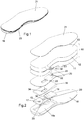
- the insole has a sensor device 10 which has a plurality of sensor fields 1-9, of which in each case a pressure acting on the respective sensor field 1-9 can be detected.
- the sensor device has sandwiched layers 11-13.
- the middle layer 12 consists of a piezoresistive material, ie, the volume resistance through the middle layer 12 (ie perpendicular to the plane of the middle layer 12) depends on the pressure load of the middle layer 12 from.
- it may be a piezoresistive nonwoven.
- a piezoresistive nonwoven may be in the form of a polyester nonwoven, which is provided with an electrically conductive material, in particular a metal or carbon, is coated.
- Such piezoresistive materials are known.
- the lower and upper layers 11, 13 have in the region 1a-9a; 1b-9b of a respective sensor field 1-9 each have an electrically conductive material 14.
- This electrically conductive material 14 is formed in the embodiment of an electrically conductive yarn with which the base material of the lower and upper layer 11, 13 is embroidered.
- a grid-shaped structure is formed by the embroidered conductive yarn.
- a respective region 1a-9a; 1b-9b could also be embroidered with the electrically conductive yarn at least substantially over the whole area.
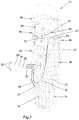
- the electrically conductive material 14 is thus arranged on the upper side of the lower layer 11 (FIG. Fig. 6 ) and on the underside of the upper layer 13 (in Fig. 7 is this, so that the electrically conductive material 14 is visible, the base material of the upper layer 13 shown transparent).
- the base material is preferably a textile material, e.g.
- the base material may be formed from a polyester fabric.
- a respective sensor field 1-9 thus comprises the respective region 1a-9a of the lower layer 11, the overlying region 1b-9b of the upper layer 13 and the intermediate section of the middle layer 12.
- the regions 1a assigned to a respective sensor field 1-9 9a; 1b-9b thus lie one above the other and, viewed in plan view, are preferably at least substantially congruent.
- the sensor device 10 is electrically conductively connected to an electronics unit 15.
- the electronic unit 15 is arranged in a recess 16 a of a sole base part 16.
- the electronic unit 15 has electronic components 17, of which only in Fig. 2 one is indicated.
- the electronic unit 15 is a circuit board that is equipped with the electronic components 17.
- an accumulator 18 is used for the power supply of the electronic unit 15. This is also arranged in the recess 16a of the sole base part 16 and electrically connected to the electronic unit 15.
- the sole base part 16 may be formed of cork, for example.
- damping layer 19 for example made of plastic, for damping shocks is arranged on the sole base part in the region of the recess 16a.
- a stabilization layer 20 which extends at least over a rear part of the sole base part 16 is arranged in the exemplary embodiment-preferably above the damping layer 19, as far as such is present.
- the stabilization layer 20 may consist of plastic.
- a layer 21 may be provided for the footrest, for example of a textile material.
- the various layers 16, 19, 20, 11, 12, 13, 24 of the insole are connected to each other, in particular by gluing and / or sewing.
- a respective tab 22, 23 is provided with conductor tracks 24, 25, 26.
- the over the tabs 22, 23 extending traces 24-26 continue on the lower layer 11 and upper layer 13 and form sensor leads 27 to the electrically conductive material 14 of the respective areas 1a-9a; 1b-9b with the conductor tracks 24, 25, 26 of the tabs 22, 23 to connect.
- nine sensor fields 1-9 are present and thus nine electrically conductive material 14 having areas 1a-9a; 1b-9b of the lower layer 11 and the upper layer 13, and both the flap 22 of the lower layer 11 and the flap 23 of the upper layer 13 has three tracks 24-26.
- the track 24 of the tab 22 of the lower layer 11 is connected to the electrically conductive material 14 in the areas 3a, 7a, 4a, the track 25 of the tab 22 with the electrically conductive material 14 in the areas 1a, 6a and 8a and the conductor track 26 of the tab 22 with the electrically conductive material 14 of the areas 2a, 5a and 9a.
- the track 24 of the tab 23 of the upper layer 13 is connected to the electrically conductive material 14 in the areas 3b, 8b, 9b, the track 25 of the tab 23 with the electrically conductive material 14 in the areas 5b, 6b and 7b and the conductor 26 of the tab 23 with the electrically conductive material 14 in the areas 1b, 2b and 4b.
- each of the electrical resistance of exactly one of the sensor fields are 1-9 measured, for example, between the track 24 of the tab 22 and the conductor 24 of the tab 23, the electrical resistance of the sensor array.
- the conductor tracks 24-26 of the lower and upper tabs 22, 23 and the sensor leads 27 of the lower layer 11 and upper layer 13 are formed in the embodiment shown by an electrically conductive yarn, with which the base material of the respective flap 22, 23 or the respective layer 11, 13 is embroidered.
- the sensor leads 27 are electrically isolated.
- the electrically conductive yarn in the region to be insulated is provided with an electrically insulating yarn 28, e.g. a polyester yarn, overstitched.
- the tabs 22, 23 are preferably material integral with the base material of the respective layer 11, 13 is formed. Although in the schematic Fig. 5 the tabs 22, 23 are shown with a lower material thickness than the respective layer 11, 13, the tabs 22, 23 may have the same material thickness as the respective layer 11, 13, as is preferred.
- the tab 22, 23 In the flat-laid state of the respective layer 11, 13 with the tab 22, 23 arranged thereon, the tab 22, 23 is laterally from the position 11, 13 and is in the same plane with this.
- the tabs 22, 23 could also be referred to as flags.
- the lower layer 11, the middle layer 12 and the upper layer 13 are superimposed and connected to each other, for example by sewing.
- the electrically conductive yarn for forming the regions 1a-9a; 1b-9b of the lower layer 11 and upper layer 13 and / or the conductor tracks 24, 26 of the tabs 22, 23 and / or the sensor leads 27 may be a multifilament yarn or monofilament yarn.
- it may be a stainless steel yarn having several hundred filaments, e.g. with a thickness in the range of 5 microns to 15 microns.
- the electrically conductive yarn may also be formed by staple fibers.
- this electrically conductive yarn can form the back thread, wherein the front thread can be formed by an electrically insulating yarn, e.g. Polyester, or vice versa.
- the tabs 22, 23 are folded over (bent or folded over about an axis lying parallel to the central plane through the respective layer 11 and parallel to the longitudinal extent of the sole) and against contact regions 29 of the electronic unit 15 created. Only in Fig. 2 two such contact areas 29 are schematically indicated on the upper side of the electronic unit 15.
- the contact regions 29 are, in particular, metallized regions of the printed circuit board of the electronic unit 15.
- clamping elements 30 are used in the exemplary embodiment.
- a respective clamping element 30 is formed by a spring-elastic tongue attached to the electronic unit 15.
- the clamping elements 30 in this case have expediently positioning pins 31, which protrude through holes 32 in the tabs 22, 23.
- the contact regions 29 for the printed conductors 24-26 of the tab 22 of the lower layer 11 are located on the upper side of the electronic unit 15 and the contact regions 29 for the printed conductors 24-26 of the upper flap 23 Position 13 at the bottom of the electronics unit 15.
- the stabilization layer 20 and the damping layer 19 have in the embodiment window openings 33, 34, through which the tabs 22, 23 are performed in the connected to the electronic unit 15 state. Instead, it would also be conceivable and possible to guide the tabs 22, 23 around these layers 19, 20 on the outside.
- the flexible tabs 22, 23 in the flat-lay state of the sensor device 10 laterally from the sensor device 10, at least substantially in a direction perpendicular to the direction of the longitudinal extent of the insole.
- the tabs 22, 23 could, for example, also project from the front or rear end of the sensor device 10 (parallel to the direction of the longitudinal extension of the insole), although this is less preferred in view of the risk of damage to the tabs 22, 23.
- the electronic unit 15 For transmission of data of the electronic unit 15, for example, to a mobile device or another outside the insole arranged microprocessor device, the electronic unit 15 preferably have a transmitting and receiving unit for wireless data transmission, for example via Bluetooth. Charging the battery 18 can also be done wirelessly in a possible embodiment. Instead or in addition, a connection socket (not shown in the figures) for data transmission and / or for charging the accumulator 18 may be present.
- the pressure acting on the various sensor fields and their time course can be detected, For example, to determine incorrect loads of the user.
- the areas 1a-9a; 1b-9b with the electrically conductive material 14 could also be formed in other ways than by embroidering with an electrically conductive yarn.
- the lower and / or upper layer 11, 13 could also be provided with a metal coating in these areas.
- the tracks 24-26 and / or sensor leads 27 could also be formed other than by embroidering with a conductive material, such as metal coatings.
- the lower and / or upper layer 11, 13 could also have as a base material instead of a textile material a film (which is embroidered with electrically conductive material and / or provided with metal coatings).
- insulations could also be formed in another way, for example by coating with an electrically insulating material.
- the embodiment shown is an insole for a shoe.
- the invention can also be used in a shoe sole of a shoe, which may be formed in an analogous manner as the illustrated insole, optionally with a correspondingly modified layer structure, for example an additional insole.
- 1 sensor field 10 sensor device 1a Area 11 lower position 1b Area 12 middle location 2 sensor field 13 upper layer 2a Area 14 electrically conductive material 2 B
- Area 15 electronics unit 3 sensor field 16 Sole base 3a Area 16a recess 3b Area 17 electronic component 4 sensor field 18 accumulator 4a Area 19 damping layer 4b
Landscapes
- Health & Medical Sciences (AREA)
- Life Sciences & Earth Sciences (AREA)
- Engineering & Computer Science (AREA)
- Molecular Biology (AREA)
- Animal Behavior & Ethology (AREA)
- Physics & Mathematics (AREA)
- Veterinary Medicine (AREA)
- Biophysics (AREA)
- Pathology (AREA)
- Biomedical Technology (AREA)
- Heart & Thoracic Surgery (AREA)
- Medical Informatics (AREA)
- Public Health (AREA)
- Surgery (AREA)
- General Health & Medical Sciences (AREA)
- Chemical & Material Sciences (AREA)
- Materials Engineering (AREA)
- Microelectronics & Electronic Packaging (AREA)
- Dentistry (AREA)
- Oral & Maxillofacial Surgery (AREA)
- Wood Science & Technology (AREA)
- Footwear And Its Accessory, Manufacturing Method And Apparatuses (AREA)
- Force Measurement Appropriate To Specific Purposes (AREA)
- Investigating Or Analyzing Materials By The Use Of Electric Means (AREA)
Claims (10)
- Semelle intérieure amovible ou semelle de chaussure, laquelle est munie d'un dispositif capteur (10) avec plusieurs champs de capteurs (1-9) pour mesurer la pression et d'une unité électronique (15) reliée électriquement aux champs de capteurs (1-9) et munie de composants électroniques (17), le dispositif capteur (10) étant conçu en sandwich avec une couche centrale (12) faite d'un matériau piézorésistant, une couche supérieure (13) disposée au-dessus de la couche centrale (12) et une couche inférieure (11) disposée en dessous de la couche centrale (12), les couches supérieure et inférieure (13, 11) étant munies, dans la zone (1a - 9a ; 1b-9b) d'un champ de capteurs (1-9) respectif, chacune d'un matériau électriquement conducteur (14), et les couches supérieure et inférieure (13, 11) étant munies chacune d'une patte flexible saillante (23, 22) présentant des pistes conductrices (24-26) en vue de relier électriquement les champs de capteurs (1-9) à l'unité électronique (15), et l'unité électronique (15) est munie de zones de contact (29) contre lesquelles les pattes (23, 22) s'appuient avec leurs pistes conductrices (24-26), une couche de stabilisation (20) et/ou une couche d'amortissement (19) étant disposée entre le dispositif capteur (10) et l'unité électronique (15).
- Semelle intérieure amovible ou semelle de chaussure selon la revendication 1, caractérisée en ce que les zones de contact (29) pour les pistes conductrices (24-26) de la patte (22) de la couche inférieure (11) sont disposées sur la face supérieure de l'unité électronique (15) et les zones de contact (29) pour les pistes conductrices (24-26) de la patte (23) de la couche supérieure (13) sont disposées sur la face inférieure de l'unité électronique (15).
- Semelle intérieure amovible ou semelle de chaussure selon la revendication 1 ou 2, caractérisée en ce que l'unité électronique (15) est munie d'une plaquette à circuit imprimé qui est équipée des composants électroniques (17), les zones de contact (29) étant formées par des zones métallisées de la plaquette à circuit imprimé de l'unité électronique (15) qui comporte les composants électroniques (17).
- Semelle intérieure amovible ou semelle de chaussure selon l'une des revendications 1 à 3, caractérisée en ce que les pattes (22, 23) sont pressées avec leurs pistes conductrices (24-26) contre les zones de contact (29) du module électronique (15) au moyen d'éléments de serrage (30).
- Semelle intérieure amovible ou semelle de chaussure selon l'une des revendications 1 à 4, caractérisée en ce qu'une patte (22, 23) respective présente au moins un trou (32) au travers duquel dépasse une broche de positionnement (31) de l'unité électronique (15) à l'état relié à l'unité électronique (15).
- Semelle intérieure amovible ou semelle de chaussure selon l'une des revendications 1 à 5, caractérisée en ce que les pattes (22, 23), à l'état relié à l'unité électronique (15), passent par une ouverture de fenêtre (33, 34) dans la couche de stabilisation (20) et/ou la couche d'amortissement (19).
- Semelle intérieure amovible ou semelle de chaussure selon l'une des revendications 1 à 6, caractérisée en ce que les couches supérieure et inférieure (13, 11) sont munie chacune d'un matériau de base flexible, de préférence textile, et la patte (23) de la couche supérieure (13) est formée d'une pièce avec le matériau de base de la couche supérieure (13), et la languette (22) de la couche inférieure (11) est formée d'une pièce avec le matériau de base de la couche inférieure (11).
- Semelle intérieure amovible ou semelle de chaussure selon l'une des revendications 1 à 7, caractérisée en ce que le matériau électriquement conducteur (14), dont sont munis la couche supérieure (13) et la couche inférieure (11) dans la zone (1a-9a ; 1b-9b) d'un champ de capteurs (1-9) respectif, est formé par un fil électriquement conducteur avec lequel est brodé un matériau de base de la couche supérieure (13) et de la couche inférieure (11).
- Semelle intérieure amovible ou semelle de chaussure selon l'une des revendications 1 à 8, caractérisée en ce que les pistes conductrices (24-26) des pattes (22, 23) sont formées par un fil électriquement conducteur avec lequel est brodé un matériau de base de la patte respective (22, 23).
- Semelle intérieure amovible ou semelle de chaussure selon l'une des revendications 1 à 9, caractérisée en ce que l'unité électronique (15) est disposée dans un évidement (16a) d'une partie de base de semelle (16), et un accumulateur (18) servant à alimenter l'unité électronique (15) en énergie est également disposé dans l'évidement (16a) de la partie de base de semelle (16) et est relié électriquement à l'unité électronique (15).
Applications Claiming Priority (1)
| Application Number | Priority Date | Filing Date | Title |
|---|---|---|---|
| ATA443/2016A AT518546B1 (de) | 2016-09-27 | 2016-09-27 | Einlegesohle oder Schuhsohle |
Publications (2)
| Publication Number | Publication Date |
|---|---|
| EP3298921A1 EP3298921A1 (fr) | 2018-03-28 |
| EP3298921B1 true EP3298921B1 (fr) | 2019-11-20 |
Family
ID=59655983
Family Applications (1)
| Application Number | Title | Priority Date | Filing Date |
|---|---|---|---|
| EP17186908.4A Active EP3298921B1 (fr) | 2016-09-27 | 2017-08-18 | Semelle intérieure de chaussure ou semelle de chaussure |
Country Status (6)
| Country | Link |
|---|---|
| US (1) | US10736542B2 (fr) |
| EP (1) | EP3298921B1 (fr) |
| JP (1) | JP7028433B2 (fr) |
| AT (1) | AT518546B1 (fr) |
| AU (1) | AU2017232093B2 (fr) |
| CA (1) | CA2979878C (fr) |
Families Citing this family (8)
| Publication number | Priority date | Publication date | Assignee | Title |
|---|---|---|---|---|
| US10806212B2 (en) * | 2015-05-29 | 2020-10-20 | Nike, Inc. | Multi-capacitor kinetic energy generator |
| GB2575654A (en) * | 2018-07-18 | 2020-01-22 | Nurvv Ltd | A sensor insert for a shoe |
| US11350877B2 (en) * | 2018-09-24 | 2022-06-07 | Arizona Board Of Regents On Behalf Of Arizona State University | Smart shoes with adaptive sampling for rehabilitation and health monitoring |
| FR3086510B1 (fr) * | 2018-10-02 | 2021-11-05 | Traxxs | Demi-semelle interne pour chaussure |
| KR102589950B1 (ko) | 2019-03-05 | 2023-10-16 | 삼성전자주식회사 | 인솔 및 이를 포함하는 신발 |
| KR102318554B1 (ko) * | 2019-09-03 | 2021-10-29 | 한국전자기술연구원 | 압력센서 |
| WO2022183166A1 (fr) * | 2021-02-26 | 2022-09-01 | Laaf, Inc. | Appareil et procédé de semelle intérieure intelligente d'analyse de données |
| JP7501484B2 (ja) * | 2021-09-28 | 2024-06-18 | 豊田合成株式会社 | 検出装置及び履物 |
Citations (2)
| Publication number | Priority date | Publication date | Assignee | Title |
|---|---|---|---|---|
| US6195921B1 (en) * | 1999-09-28 | 2001-03-06 | Vinncente Hoa Gia Truong | Virtual intelligence shoe with a podiatric analysis system |
| US6216545B1 (en) * | 1995-11-14 | 2001-04-17 | Geoffrey L. Taylor | Piezoresistive foot pressure measurement |
Family Cites Families (69)
| Publication number | Priority date | Publication date | Assignee | Title |
|---|---|---|---|---|
| JPH089901Y2 (ja) * | 1990-08-16 | 1996-03-21 | 株式会社横尾製作所 | フラットケーブル用コネクター |
| WO2000064293A1 (fr) | 1999-04-26 | 2000-11-02 | Anatomic Res Inc | Structures orthopediques de semelles de chaussures et compartiments regles par ordinateur |
| DE10201134A1 (de) | 2002-01-08 | 2003-07-10 | Mohammad Nasseri | Verfahren und Vorrichtung zur Messwerterfassung und -auswertung in Schuhen bzw. Schuheinlagen |
| DE102004017605B3 (de) * | 2004-04-07 | 2005-10-20 | Adc Gmbh | Steckverbinder für Leiterplatten sowie Verteileranschlussmodul |
| JP4076170B2 (ja) * | 2004-08-16 | 2008-04-16 | 日本航空電子工業株式会社 | コネクタ |
| US7632239B2 (en) | 2005-11-16 | 2009-12-15 | Bioness Neuromodulation Ltd. | Sensor device for gait enhancement |
| DE102006025447A1 (de) | 2006-05-31 | 2007-12-27 | Lenhart, Peter, Dr. med. | Sensoreinrichtung sowie Verfahren zur Generierung und Visualisierung hinsichtlich der Laufmotorik einer Person indikativer Signale |
| JP5010238B2 (ja) | 2006-10-31 | 2012-08-29 | 京セラディスプレイ株式会社 | 電極基板 |
| US20100004566A1 (en) | 2008-01-11 | 2010-01-07 | Esoles, L,L.C. | Intelligent orthotic insoles |
| US8384551B2 (en) | 2008-05-28 | 2013-02-26 | MedHab, LLC | Sensor device and method for monitoring physical stresses placed on a user |
| US9549585B2 (en) * | 2008-06-13 | 2017-01-24 | Nike, Inc. | Footwear having sensor system |
| US8676541B2 (en) | 2008-06-13 | 2014-03-18 | Nike, Inc. | Footwear having sensor system |
| CN102308270B (zh) | 2009-02-06 | 2015-05-27 | 压力分布系统公司 | 电容式接近触觉传感器 |
| US8968218B2 (en) | 2009-02-11 | 2015-03-03 | Interactive Metronome, Inc. | Gait symmetry measurement and improvement |
| DE102010049154A1 (de) | 2009-10-22 | 2011-06-16 | Moticon Gmbh | Sohle mit Sensor |
| DE102009060794A1 (de) | 2009-12-31 | 2011-07-07 | Moticon GmbH, 80469 | Steuerung mobiler elektronischer Systeme |
| DE102010012037A1 (de) | 2010-03-19 | 2011-09-22 | Moticon Gmbh | Vorrichtung zur Bereitstellung von Trainings-Feedback im Golfsport |
| DE102010013671A1 (de) | 2010-04-01 | 2011-10-06 | Moticon Gmbh | Trainings-Vorrichtung für den Golfsport |
| EP2422698A1 (fr) | 2010-08-26 | 2012-02-29 | Nederlandse Organisatie voor toegepast -natuurwetenschappelijk onderzoek TNO | Procédé et système pour déterminer la vitesse de marche ou de course d'une personne |
| US20140149072A1 (en) | 2010-10-22 | 2014-05-29 | Corpus.E Ag | Scanner-Assisted Selection of Fitting Footwear with Individualized Footbed |
| DE102011009969A1 (de) | 2011-02-01 | 2012-08-02 | Moticon Gmbh | Leitende Strukturen aus Textil |
| JP5805404B2 (ja) | 2011-02-21 | 2015-11-04 | セイコーインスツル株式会社 | バリア液晶装置及び立体画像表示装置 |
| DE102011012458A1 (de) | 2011-02-25 | 2012-08-30 | Moticon Gmbh | Sohle mit Sensor |
| DE102011100933A1 (de) | 2011-05-09 | 2012-11-15 | Moticon Gmbh | Elektronische Skibindung |
| GB2495967B (en) | 2011-10-27 | 2018-03-21 | Salisbury Nhs Found Trust | Wireless footswitch and functional electrical stimulation apparatus |
| KR101283434B1 (ko) | 2011-11-29 | 2013-07-08 | 이진욱 | 보행 진단을 위한 신발 인솔 센서 및 이와 접촉되는 신발 인솔 기판 |
| DE102011122659A1 (de) | 2011-12-30 | 2013-07-04 | Moticon Gmbh | Verfahren zur Synchronisierung von Multimediadaten |
| US20130213146A1 (en) * | 2012-02-22 | 2013-08-22 | Nike, Inc. | Footwear Having Sensor System |
| DE102012004117A1 (de) | 2012-03-01 | 2013-09-05 | Moticon Gmbh | Sohle mit Sensor |
| ES2437718B1 (es) | 2012-07-04 | 2014-08-27 | Sensing Tex, S.L. | Sensor de presión extensible de gran área para superficies textiles |
| DE102012106715A1 (de) | 2012-07-24 | 2014-01-30 | Fachhochschule Münster | Vorrichtung zur Lastgrößenerfassung an einem biologischen System |
| KR102006027B1 (ko) | 2012-11-09 | 2019-07-31 | 지이 하이브리드 테크놀로지스, 엘엘씨 | 무선 충전이 가능한 신발 및 이에 사용되는 무선 충전 기기 |
| WO2014100045A1 (fr) | 2012-12-17 | 2014-06-26 | Qi2 ELEMENTS II, LLC | Systèmes de capteurs montés sur un pied permettant de suivre les mouvements du corps |
| DE102013202878A1 (de) | 2013-02-21 | 2014-09-04 | Elke Hack | Vorrichtung zur Detektion fehlerhaften Gehverhaltens |
| RU2531697C1 (ru) | 2013-03-05 | 2014-10-27 | Общество С Ограниченной Ответственностью "Хилби" | Способ определения веса человека и стелька, предназначенная для его осуществления |
| RU2531689C1 (ru) | 2013-03-05 | 2014-10-27 | Общество С Ограниченной Ответственностью "Хилби" | Способ мониторинга двигательной нагрузки человека и стелька, предназначенная для его осуществления |
| US20140266570A1 (en) | 2013-03-12 | 2014-09-18 | Anirudh Sharma | System and method for haptic based interaction |
| CN103169598B (zh) | 2013-03-15 | 2014-10-29 | 华中科技大学 | 一种可穿戴式的智能导盲系统及方法 |
| EP2783630A1 (fr) | 2013-03-27 | 2014-10-01 | ETH Zurich | Procédé d'analyse de mouvement chez l'homme et dispositif |
| DE102013210213A1 (de) | 2013-06-01 | 2014-12-04 | Simi Reality Motion Systems Gmbh | Verfahren und Vorrichtung zur Überwachung und/oder Einübung des Fußaufsatzes im Schrittzyklus eines menschlichen Individuums |
| ES2485617B1 (es) | 2013-09-16 | 2015-04-06 | Sensing Tex, S.L. | Sensor textil piezo-resistivo y sistema de detección del ritmo cardiaco y/o respiratorio |
| DE102013015848A1 (de) | 2013-09-24 | 2015-03-26 | Moticon Gmbh | Sohle mit Sensor |
| KR101560803B1 (ko) | 2014-01-23 | 2015-11-10 | 동서대학교산학협력단 | 자세 교정 기능이 내장된 스마트 운동화 제공 시스템을 이용한 자세 교정 방법 |
| KR101530225B1 (ko) | 2014-04-02 | 2015-06-22 | 경희대학교 산학협력단 | 나노섬유 웹을 이용한 하이브리드 압력센서가 구비된 스마트 슈즈 시스템 |
| US9568381B2 (en) * | 2014-05-15 | 2017-02-14 | Henry J. Daniecki | Lower limb force sensing system |
| CN104172641A (zh) | 2014-08-14 | 2014-12-03 | 彭君秀 | 一种鞋子、鞋垫智能监测方法 |
| CN204146420U (zh) | 2014-08-14 | 2015-02-11 | 彭君秀 | 一种鞋子、鞋垫智能监测系统 |
| ES2570585B1 (es) | 2014-11-17 | 2017-01-25 | Sensing Tex, S.L. | Control y alimentación alámbrica textil entre dispositivos móviles y textiles inteligentes |
| CN104522932B (zh) | 2014-12-05 | 2016-04-27 | 东莞市舒健智能科技有限公司 | 一种智能鞋垫或鞋的控制方法及系统 |
| CA2967171A1 (fr) | 2014-12-10 | 2016-06-16 | Hci Viocare Technologies Ltd. | Dispositif de detection de force |
| CN105266256A (zh) | 2015-01-04 | 2016-01-27 | 邢台职业技术学院 | 一种老年人专用平衡鞋 |
| WO2016111425A1 (fr) | 2015-01-05 | 2016-07-14 | 주식회사 비엠시스 | Semelle intérieure intelligente possédant une structure dans laquelle un ensemble capteur permettant l'acquisition d'informations d'exercice peut être attaché/détaché, et jeu de semelle intérieure intelligente-ensemble capteur |
| US20160349076A1 (en) | 2015-01-21 | 2016-12-01 | Multiservicios Profesionales De Esparza, S.A. | Nanopedometer |
| US9863823B2 (en) * | 2015-02-27 | 2018-01-09 | Bebop Sensors, Inc. | Sensor systems integrated with footwear |
| CN204580070U (zh) | 2015-03-30 | 2015-08-26 | 茂泰(福建)鞋材有限公司 | 一种新式暖足鞋底及设有该鞋底的鞋 |
| DE202015004254U1 (de) | 2015-06-16 | 2015-10-05 | Martin Bücherl | Druckempfindliche textile Sensorfläche |
| CN205215232U (zh) | 2015-08-29 | 2016-05-11 | 深圳市第二人民医院 | 一种基于鞋垫的步态检测系统 |
| WO2017048979A1 (fr) * | 2015-09-15 | 2017-03-23 | The Arizona Board Of Regents On Behalf Of The University Of Arizona | Textile intelligent permettant de prédire le risque d'ulcère du pied diabétique |
| CN105380342A (zh) | 2015-10-14 | 2016-03-09 | 上海交通大学 | 一种基于电容式压力传感器的智能鞋垫系统 |
| CN105231577A (zh) | 2015-10-19 | 2016-01-13 | 重庆小爱科技有限公司 | 一种智能孕妇鞋 |
| CN105266257A (zh) | 2015-11-05 | 2016-01-27 | 安徽埃力智能科技有限公司 | 基于全足压力信息获取的智能鞋 |
| CN205082778U (zh) | 2015-11-06 | 2016-03-16 | 宁波力芯科信息科技有限公司 | 一种多功能智能鞋垫和智能鞋 |
| CN205321406U (zh) | 2015-12-16 | 2016-06-22 | 厦门市踏踏联盟科技有限公司 | 一种智能测重鞋垫 |
| CN205306138U (zh) | 2015-12-16 | 2016-06-15 | 厦门市踏踏联盟科技有限公司 | 一种运动检测和体感控制鞋垫 |
| US20170188950A1 (en) * | 2015-12-30 | 2017-07-06 | Motion Metrix Corporation | Shoe insert for monitoring of biomechanics and motion |
| CN205358441U (zh) | 2015-12-31 | 2016-07-06 | 广东盛世商潮网络科技有限公司 | 一种智能鞋垫 |
| CN105725982A (zh) | 2016-01-25 | 2016-07-06 | 东华大学 | 一种基于光纤传感技术的鞋底温度、压力测试鞋垫 |
| CN105662418A (zh) | 2016-03-11 | 2016-06-15 | 萨科(厦门)医疗科技有限公司 | 一种无线遥感腕表测力鞋系统 |
| CN105662423B (zh) | 2016-03-30 | 2018-06-19 | 李宁体育(上海)有限公司 | 脚掌落地方式检测设备及方法、包括该设备的鞋垫和鞋 |
-
2016
- 2016-09-27 AT ATA443/2016A patent/AT518546B1/de active
-
2017
- 2017-08-18 EP EP17186908.4A patent/EP3298921B1/fr active Active
- 2017-09-19 CA CA2979878A patent/CA2979878C/fr active Active
- 2017-09-20 AU AU2017232093A patent/AU2017232093B2/en active Active
- 2017-09-22 JP JP2017183038A patent/JP7028433B2/ja active Active
- 2017-09-27 US US15/716,958 patent/US10736542B2/en active Active
Patent Citations (2)
| Publication number | Priority date | Publication date | Assignee | Title |
|---|---|---|---|---|
| US6216545B1 (en) * | 1995-11-14 | 2001-04-17 | Geoffrey L. Taylor | Piezoresistive foot pressure measurement |
| US6195921B1 (en) * | 1999-09-28 | 2001-03-06 | Vinncente Hoa Gia Truong | Virtual intelligence shoe with a podiatric analysis system |
Also Published As
| Publication number | Publication date |
|---|---|
| AU2017232093B2 (en) | 2022-11-10 |
| EP3298921A1 (fr) | 2018-03-28 |
| US10736542B2 (en) | 2020-08-11 |
| CA2979878C (fr) | 2025-01-07 |
| AT518546B1 (de) | 2017-11-15 |
| CA2979878A1 (fr) | 2018-03-27 |
| JP7028433B2 (ja) | 2022-03-02 |
| AU2017232093A1 (en) | 2018-04-12 |
| US20180085030A1 (en) | 2018-03-29 |
| AT518546A4 (de) | 2017-11-15 |
| JP2018051309A (ja) | 2018-04-05 |
Similar Documents
| Publication | Publication Date | Title |
|---|---|---|
| AT518546B1 (de) | Einlegesohle oder Schuhsohle | |
| EP3032999B1 (fr) | Électrode capacitive textile et procédé de fabrication de ladite électrode | |
| AT412756B (de) | Medizinische elektrode | |
| EP0279361B1 (fr) | Dispositif pour la mesure de la distributiom de la force de pression dans une surface | |
| DE2912049A1 (de) | Tasten-signaleingabevorrichtung fuer flache elektronische geraete | |
| EP3440444A1 (fr) | Tissu comportant plusieurs couches de tissu | |
| DE112013002836T5 (de) | Drucksensor, z. B. für ein Fussbekleidungsstück | |
| DE112012000006T5 (de) | Fussbekleidungsstück mit Drucksensor | |
| EP2147502A2 (fr) | Capteur tactile comportant des cellules de détection découplées | |
| DE112012002701T5 (de) | Folientyp-Drucksensor, z. B. für einen Fussbekleidungsartikel | |
| DE2901416A1 (de) | Anordnung zum elektrischen verbinden einer vielzahl von anschluessen | |
| EP0350638A2 (fr) | Capteur tactile | |
| EP1924947B1 (fr) | Protection contre les manipulations et les perforations pour un dispositif a relier avec un circuit electrique | |
| DE3302892C2 (fr) | ||
| DE102010049154A1 (de) | Sohle mit Sensor | |
| EP4004510B1 (fr) | Capteur brodé | |
| DE102005016676B4 (de) | Leiterbahn für elektronische Zwecke | |
| DE2851858A1 (de) | Kontaktiervorrichtung | |
| EP0538432B1 (fr) | Dispositif pour la realisation d'un circuit electrique, en particulier pour une sonde de mesure, et sonde de mesure | |
| DE2363320C3 (de) | Antistatischer Schuh | |
| DE3207051A1 (de) | Halterung zur aufnahme einer fluessigkristallanzeige | |
| DE102024002908A1 (de) | Elektronische Schaltung auf einem textilen Träger und Herstellverfahren | |
| WO2006103048A1 (fr) | Capteur de mesure de répartition de forces souple multicouche | |
| DE102024210522A1 (de) | Textilelektronikvorrichtung und Verfahren zur Herstellung einer Textilelektronikvorrichtung | |
| DE102013014803B4 (de) | Positionssensoreinrichtung |
Legal Events
| Date | Code | Title | Description |
|---|---|---|---|
| PUAI | Public reference made under article 153(3) epc to a published international application that has entered the european phase |
Free format text: ORIGINAL CODE: 0009012 |
|
| STAA | Information on the status of an ep patent application or granted ep patent |
Free format text: STATUS: THE APPLICATION HAS BEEN PUBLISHED |
|
| AK | Designated contracting states |
Kind code of ref document: A1 Designated state(s): AL AT BE BG CH CY CZ DE DK EE ES FI FR GB GR HR HU IE IS IT LI LT LU LV MC MK MT NL NO PL PT RO RS SE SI SK SM TR |
|
| AX | Request for extension of the european patent |
Extension state: BA ME |
|
| STAA | Information on the status of an ep patent application or granted ep patent |
Free format text: STATUS: REQUEST FOR EXAMINATION WAS MADE |
|
| 17P | Request for examination filed |
Effective date: 20180525 |
|
| RBV | Designated contracting states (corrected) |
Designated state(s): AL AT BE BG CH CY CZ DE DK EE ES FI FR GB GR HR HU IE IS IT LI LT LU LV MC MK MT NL NO PL PT RO RS SE SI SK SM TR |
|
| STAA | Information on the status of an ep patent application or granted ep patent |
Free format text: STATUS: EXAMINATION IS IN PROGRESS |
|
| 17Q | First examination report despatched |
Effective date: 20190314 |
|
| GRAP | Despatch of communication of intention to grant a patent |
Free format text: ORIGINAL CODE: EPIDOSNIGR1 |
|
| STAA | Information on the status of an ep patent application or granted ep patent |
Free format text: STATUS: GRANT OF PATENT IS INTENDED |
|
| INTG | Intention to grant announced |
Effective date: 20190802 |
|
| GRAS | Grant fee paid |
Free format text: ORIGINAL CODE: EPIDOSNIGR3 |
|
| GRAA | (expected) grant |
Free format text: ORIGINAL CODE: 0009210 |
|
| STAA | Information on the status of an ep patent application or granted ep patent |
Free format text: STATUS: THE PATENT HAS BEEN GRANTED |
|
| AK | Designated contracting states |
Kind code of ref document: B1 Designated state(s): AL AT BE BG CH CY CZ DE DK EE ES FI FR GB GR HR HU IE IS IT LI LT LU LV MC MK MT NL NO PL PT RO RS SE SI SK SM TR |
|
| REG | Reference to a national code |
Ref country code: GB Ref legal event code: FG4D Free format text: NOT ENGLISH |
|
| REG | Reference to a national code |
Ref country code: CH Ref legal event code: EP |
|
| REG | Reference to a national code |
Ref country code: DE Ref legal event code: R096 Ref document number: 502017002905 Country of ref document: DE |
|
| REG | Reference to a national code |
Ref country code: IE Ref legal event code: FG4D Free format text: LANGUAGE OF EP DOCUMENT: GERMAN |
|
| REG | Reference to a national code |
Ref country code: AT Ref legal event code: REF Ref document number: 1203155 Country of ref document: AT Kind code of ref document: T Effective date: 20191215 |
|
| REG | Reference to a national code |
Ref country code: NL Ref legal event code: MP Effective date: 20191120 |
|
| REG | Reference to a national code |
Ref country code: LT Ref legal event code: MG4D |
|
| PG25 | Lapsed in a contracting state [announced via postgrant information from national office to epo] |
Ref country code: NL Free format text: LAPSE BECAUSE OF FAILURE TO SUBMIT A TRANSLATION OF THE DESCRIPTION OR TO PAY THE FEE WITHIN THE PRESCRIBED TIME-LIMIT Effective date: 20191120 Ref country code: GR Free format text: LAPSE BECAUSE OF FAILURE TO SUBMIT A TRANSLATION OF THE DESCRIPTION OR TO PAY THE FEE WITHIN THE PRESCRIBED TIME-LIMIT Effective date: 20200221 Ref country code: LT Free format text: LAPSE BECAUSE OF FAILURE TO SUBMIT A TRANSLATION OF THE DESCRIPTION OR TO PAY THE FEE WITHIN THE PRESCRIBED TIME-LIMIT Effective date: 20191120 Ref country code: FI Free format text: LAPSE BECAUSE OF FAILURE TO SUBMIT A TRANSLATION OF THE DESCRIPTION OR TO PAY THE FEE WITHIN THE PRESCRIBED TIME-LIMIT Effective date: 20191120 Ref country code: BG Free format text: LAPSE BECAUSE OF FAILURE TO SUBMIT A TRANSLATION OF THE DESCRIPTION OR TO PAY THE FEE WITHIN THE PRESCRIBED TIME-LIMIT Effective date: 20200220 Ref country code: SE Free format text: LAPSE BECAUSE OF FAILURE TO SUBMIT A TRANSLATION OF THE DESCRIPTION OR TO PAY THE FEE WITHIN THE PRESCRIBED TIME-LIMIT Effective date: 20191120 Ref country code: LV Free format text: LAPSE BECAUSE OF FAILURE TO SUBMIT A TRANSLATION OF THE DESCRIPTION OR TO PAY THE FEE WITHIN THE PRESCRIBED TIME-LIMIT Effective date: 20191120 Ref country code: NO Free format text: LAPSE BECAUSE OF FAILURE TO SUBMIT A TRANSLATION OF THE DESCRIPTION OR TO PAY THE FEE WITHIN THE PRESCRIBED TIME-LIMIT Effective date: 20200220 |
|
| PG25 | Lapsed in a contracting state [announced via postgrant information from national office to epo] |
Ref country code: RS Free format text: LAPSE BECAUSE OF FAILURE TO SUBMIT A TRANSLATION OF THE DESCRIPTION OR TO PAY THE FEE WITHIN THE PRESCRIBED TIME-LIMIT Effective date: 20191120 Ref country code: HR Free format text: LAPSE BECAUSE OF FAILURE TO SUBMIT A TRANSLATION OF THE DESCRIPTION OR TO PAY THE FEE WITHIN THE PRESCRIBED TIME-LIMIT Effective date: 20191120 Ref country code: IS Free format text: LAPSE BECAUSE OF FAILURE TO SUBMIT A TRANSLATION OF THE DESCRIPTION OR TO PAY THE FEE WITHIN THE PRESCRIBED TIME-LIMIT Effective date: 20200320 |
|
| PG25 | Lapsed in a contracting state [announced via postgrant information from national office to epo] |
Ref country code: AL Free format text: LAPSE BECAUSE OF FAILURE TO SUBMIT A TRANSLATION OF THE DESCRIPTION OR TO PAY THE FEE WITHIN THE PRESCRIBED TIME-LIMIT Effective date: 20191120 |
|
| PG25 | Lapsed in a contracting state [announced via postgrant information from national office to epo] |
Ref country code: RO Free format text: LAPSE BECAUSE OF FAILURE TO SUBMIT A TRANSLATION OF THE DESCRIPTION OR TO PAY THE FEE WITHIN THE PRESCRIBED TIME-LIMIT Effective date: 20191120 Ref country code: CZ Free format text: LAPSE BECAUSE OF FAILURE TO SUBMIT A TRANSLATION OF THE DESCRIPTION OR TO PAY THE FEE WITHIN THE PRESCRIBED TIME-LIMIT Effective date: 20191120 Ref country code: ES Free format text: LAPSE BECAUSE OF FAILURE TO SUBMIT A TRANSLATION OF THE DESCRIPTION OR TO PAY THE FEE WITHIN THE PRESCRIBED TIME-LIMIT Effective date: 20191120 Ref country code: EE Free format text: LAPSE BECAUSE OF FAILURE TO SUBMIT A TRANSLATION OF THE DESCRIPTION OR TO PAY THE FEE WITHIN THE PRESCRIBED TIME-LIMIT Effective date: 20191120 Ref country code: PT Free format text: LAPSE BECAUSE OF FAILURE TO SUBMIT A TRANSLATION OF THE DESCRIPTION OR TO PAY THE FEE WITHIN THE PRESCRIBED TIME-LIMIT Effective date: 20200412 Ref country code: DK Free format text: LAPSE BECAUSE OF FAILURE TO SUBMIT A TRANSLATION OF THE DESCRIPTION OR TO PAY THE FEE WITHIN THE PRESCRIBED TIME-LIMIT Effective date: 20191120 |
|
| REG | Reference to a national code |
Ref country code: DE Ref legal event code: R097 Ref document number: 502017002905 Country of ref document: DE |
|
| PG25 | Lapsed in a contracting state [announced via postgrant information from national office to epo] |
Ref country code: SM Free format text: LAPSE BECAUSE OF FAILURE TO SUBMIT A TRANSLATION OF THE DESCRIPTION OR TO PAY THE FEE WITHIN THE PRESCRIBED TIME-LIMIT Effective date: 20191120 Ref country code: SK Free format text: LAPSE BECAUSE OF FAILURE TO SUBMIT A TRANSLATION OF THE DESCRIPTION OR TO PAY THE FEE WITHIN THE PRESCRIBED TIME-LIMIT Effective date: 20191120 |
|
| PLBE | No opposition filed within time limit |
Free format text: ORIGINAL CODE: 0009261 |
|
| STAA | Information on the status of an ep patent application or granted ep patent |
Free format text: STATUS: NO OPPOSITION FILED WITHIN TIME LIMIT |
|
| 26N | No opposition filed |
Effective date: 20200821 |
|
| PG25 | Lapsed in a contracting state [announced via postgrant information from national office to epo] |
Ref country code: SI Free format text: LAPSE BECAUSE OF FAILURE TO SUBMIT A TRANSLATION OF THE DESCRIPTION OR TO PAY THE FEE WITHIN THE PRESCRIBED TIME-LIMIT Effective date: 20191120 Ref country code: PL Free format text: LAPSE BECAUSE OF FAILURE TO SUBMIT A TRANSLATION OF THE DESCRIPTION OR TO PAY THE FEE WITHIN THE PRESCRIBED TIME-LIMIT Effective date: 20191120 |
|
| PG25 | Lapsed in a contracting state [announced via postgrant information from national office to epo] |
Ref country code: IT Free format text: LAPSE BECAUSE OF FAILURE TO SUBMIT A TRANSLATION OF THE DESCRIPTION OR TO PAY THE FEE WITHIN THE PRESCRIBED TIME-LIMIT Effective date: 20191120 |
|
| PG25 | Lapsed in a contracting state [announced via postgrant information from national office to epo] |
Ref country code: MC Free format text: LAPSE BECAUSE OF FAILURE TO SUBMIT A TRANSLATION OF THE DESCRIPTION OR TO PAY THE FEE WITHIN THE PRESCRIBED TIME-LIMIT Effective date: 20191120 |
|
| PG25 | Lapsed in a contracting state [announced via postgrant information from national office to epo] |
Ref country code: LU Free format text: LAPSE BECAUSE OF NON-PAYMENT OF DUE FEES Effective date: 20200818 |
|
| REG | Reference to a national code |
Ref country code: BE Ref legal event code: MM Effective date: 20200831 |
|
| PG25 | Lapsed in a contracting state [announced via postgrant information from national office to epo] |
Ref country code: IE Free format text: LAPSE BECAUSE OF NON-PAYMENT OF DUE FEES Effective date: 20200818 Ref country code: BE Free format text: LAPSE BECAUSE OF NON-PAYMENT OF DUE FEES Effective date: 20200831 |
|
| PG25 | Lapsed in a contracting state [announced via postgrant information from national office to epo] |
Ref country code: TR Free format text: LAPSE BECAUSE OF FAILURE TO SUBMIT A TRANSLATION OF THE DESCRIPTION OR TO PAY THE FEE WITHIN THE PRESCRIBED TIME-LIMIT Effective date: 20191120 Ref country code: MT Free format text: LAPSE BECAUSE OF FAILURE TO SUBMIT A TRANSLATION OF THE DESCRIPTION OR TO PAY THE FEE WITHIN THE PRESCRIBED TIME-LIMIT Effective date: 20191120 Ref country code: CY Free format text: LAPSE BECAUSE OF FAILURE TO SUBMIT A TRANSLATION OF THE DESCRIPTION OR TO PAY THE FEE WITHIN THE PRESCRIBED TIME-LIMIT Effective date: 20191120 |
|
| PG25 | Lapsed in a contracting state [announced via postgrant information from national office to epo] |
Ref country code: MK Free format text: LAPSE BECAUSE OF FAILURE TO SUBMIT A TRANSLATION OF THE DESCRIPTION OR TO PAY THE FEE WITHIN THE PRESCRIBED TIME-LIMIT Effective date: 20191120 |
|
| REG | Reference to a national code |
Ref country code: AT Ref legal event code: MM01 Ref document number: 1203155 Country of ref document: AT Kind code of ref document: T Effective date: 20220818 |
|
| PG25 | Lapsed in a contracting state [announced via postgrant information from national office to epo] |
Ref country code: AT Free format text: LAPSE BECAUSE OF NON-PAYMENT OF DUE FEES Effective date: 20220818 |
|
| PGFP | Annual fee paid to national office [announced via postgrant information from national office to epo] |
Ref country code: DE Payment date: 20250827 Year of fee payment: 9 |
|
| PGFP | Annual fee paid to national office [announced via postgrant information from national office to epo] |
Ref country code: GB Payment date: 20250826 Year of fee payment: 9 |
|
| PGFP | Annual fee paid to national office [announced via postgrant information from national office to epo] |
Ref country code: FR Payment date: 20250825 Year of fee payment: 9 |
|
| PGFP | Annual fee paid to national office [announced via postgrant information from national office to epo] |
Ref country code: CH Payment date: 20250901 Year of fee payment: 9 |