EP4004510B1 - Capteur brodé - Google Patents
Capteur brodé Download PDFInfo
- Publication number
- EP4004510B1 EP4004510B1 EP20746164.1A EP20746164A EP4004510B1 EP 4004510 B1 EP4004510 B1 EP 4004510B1 EP 20746164 A EP20746164 A EP 20746164A EP 4004510 B1 EP4004510 B1 EP 4004510B1
- Authority
- EP
- European Patent Office
- Prior art keywords
- electrode
- thread
- sensor
- carrier
- cover layer
- Prior art date
- Legal status (The legal status is an assumption and is not a legal conclusion. Google has not performed a legal analysis and makes no representation as to the accuracy of the status listed.)
- Active
Links
Images


Classifications
-
- G—PHYSICS
- G01—MEASURING; TESTING
- G01L—MEASURING FORCE, STRESS, TORQUE, WORK, MECHANICAL POWER, MECHANICAL EFFICIENCY, OR FLUID PRESSURE
- G01L1/00—Measuring force or stress, in general
- G01L1/20—Measuring force or stress, in general by measuring variations in ohmic resistance of solid materials or of electrically-conductive fluids; by making use of electrokinetic cells, i.e. liquid-containing cells wherein an electrical potential is produced or varied upon the application of stress
- G01L1/205—Measuring force or stress, in general by measuring variations in ohmic resistance of solid materials or of electrically-conductive fluids; by making use of electrokinetic cells, i.e. liquid-containing cells wherein an electrical potential is produced or varied upon the application of stress using distributed sensing elements
-
- G—PHYSICS
- G01—MEASURING; TESTING
- G01L—MEASURING FORCE, STRESS, TORQUE, WORK, MECHANICAL POWER, MECHANICAL EFFICIENCY, OR FLUID PRESSURE
- G01L1/00—Measuring force or stress, in general
- G01L1/18—Measuring force or stress, in general using properties of piezo-resistive materials, i.e. materials of which the ohmic resistance varies according to changes in magnitude or direction of force applied to the material
-
- D—TEXTILES; PAPER
- D02—YARNS; MECHANICAL FINISHING OF YARNS OR ROPES; WARPING OR BEAMING
- D02G—CRIMPING OR CURLING FIBRES, FILAMENTS, THREADS, OR YARNS; YARNS OR THREADS
- D02G3/00—Yarns or threads, e.g. fancy yarns; Processes or apparatus for the production thereof, not otherwise provided for
- D02G3/44—Yarns or threads characterised by the purpose for which they are designed
- D02G3/441—Yarns or threads with antistatic, conductive or radiation-shielding properties
-
- D—TEXTILES; PAPER
- D05—SEWING; EMBROIDERING; TUFTING
- D05D—INDEXING SCHEME ASSOCIATED WITH SUBCLASSES D05B AND D05C, RELATING TO SEWING, EMBROIDERING AND TUFTING
- D05D2303/00—Applied objects or articles
- D05D2303/40—Electronic or electrical components
-
- D—TEXTILES; PAPER
- D10—INDEXING SCHEME ASSOCIATED WITH SUBLASSES OF SECTION D, RELATING TO TEXTILES
- D10B—INDEXING SCHEME ASSOCIATED WITH SUBLASSES OF SECTION D, RELATING TO TEXTILES
- D10B2401/00—Physical properties
- D10B2401/16—Physical properties antistatic; conductive
-
- D—TEXTILES; PAPER
- D10—INDEXING SCHEME ASSOCIATED WITH SUBLASSES OF SECTION D, RELATING TO TEXTILES
- D10B—INDEXING SCHEME ASSOCIATED WITH SUBLASSES OF SECTION D, RELATING TO TEXTILES
- D10B2401/00—Physical properties
- D10B2401/18—Physical properties including electronic components
-
- D—TEXTILES; PAPER
- D10—INDEXING SCHEME ASSOCIATED WITH SUBLASSES OF SECTION D, RELATING TO TEXTILES
- D10B—INDEXING SCHEME ASSOCIATED WITH SUBLASSES OF SECTION D, RELATING TO TEXTILES
- D10B2403/00—Details of fabric structure established in the fabric forming process
- D10B2403/02—Cross-sectional features
- D10B2403/024—Fabric incorporating additional compounds
- D10B2403/0243—Fabric incorporating additional compounds enhancing functional properties
- D10B2403/02431—Fabric incorporating additional compounds enhancing functional properties with electronic components, e.g. sensors or switches
Definitions
- the invention relates to a sensor configured to detect and/or measure a force acting on the sensor.
- the sensor preferably operates piezoresistively.
- the sensor can detect or measure an applied compressive or bending force. It is arranged, in particular, on a flexible carrier, which can be formed, for example, from a textile material.
- the textile material used can be, for example, a woven textile material and/or a knitted textile material and/or a warp-knitted textile material and/or a nonwoven material.
- US 2003/0119391 A1 discloses a sensor for detecting an applied force.
- the sensor may comprise a textile material with a first electrode made of first conductors and a second electrode made of second conductors.
- the conductors may be arranged in a matrix configuration by stitching.
- a textile pressure sensor with conductive layers or strips and a separating insulator is known.
- the layers can be manufactured by weaving or knitting.
- the well-known pressure sensor is designed for integration into textile products.
- the pressure sensor has a multilayered thread, with one layer being a pressure-sensitive layer.
- the thread can be integrated into the textile product by weaving, knitting, warp-knitting, or sewing.
- US 2016/0328043 A1 describes a sensor in which a conductive pattern is embroidered onto a flexible carrier.
- the sensor is designed as a capacitive sensor.
- the conductive pattern has conductive nodes.
- a cover layer has conductive mating contacts.
- An intermediate layer is present between the cover layer and the carrier, adjacent to the conductive nodes and the mating contacts, in order to create a distance between a node and an opposite mating contact as long as no force acts on the cover layer.
- the cover layer is pressed in, the mating contact comes into contact with the node and can establish an electrical connection.
- a keyboard can be formed, for example.
- US 9 816 799 B2 discloses a deformation sensor with an electrically conductive element applied to or incorporated into a textile carrier. Deformations of the textile carrier can be detected because the resulting change in the distance between sections of the electrically conductive element.
- the electrically conductive element can, for example, be arranged in a meandering pattern. Alternatively, two electrically conductive elements can be present in an interdigital arrangement.
- US 2017/0261388 A1 describes a pressure sensor made up of interdigital electrodes printed on a substrate. Printing electrodes is not readily possible on all substrates. Depending on the structure and material of the substrate, capillary effects can lead to Errors can occur when printing the electrodes, for example with textile carriers.
- US 8 701 578 B2 Describes a garment in which embroidered patterns are applied to create an electrically conductive communication path. Sensors can be connected to these embroidered communication paths.
- US 7 770 473 B2 discloses a pressure sensor made of a multilayer yarn with conductive fibers and a pressure-sensitive layer. Such a multilayer yarn can be incorporated into a knitted fabric as a standing thread. The pressure sensor is formed by the multilayer yarn itself.
- Interlink Electronics offers a touch sensor with a variable resistor called FFR® . It consists of several polymer layers bonded together by lamination. One polymer layer is coated with interdigitating electrodes, while the other polymer layer is coated with a special semiconductor material. By applying pressure, the electrodes can be connected in parallel via the semiconductor material.
- the sensor according to the invention is designed to detect and/or measure a force acting on the sensor.
- the acting force can be digitally recorded.
- a value dependent on the magnitude of the acting force can be A force-dependent sensor variable, particularly an electrical sensor variable, is generated by the sensor.
- the sensor preferably operates piezoresistively for this purpose.
- the sensor can be used, for example, as a pressure sensor or bending sensor.
- the sensor has a carrier.
- the carrier is preferably made of a flexible material.
- the carrier is a planar element that is essentially 2-dimensional or 2.5-dimensional. This is understood to mean a planar element that has a thickness that is at least one order of magnitude smaller than the length and width in a plane in which the carrier extends.
- a textile material such as a woven fabric, a knitted fabric, a warp-knitted fabric, or a nonwoven material, or any combination thereof, can be used as the carrier.
- the carrier or textile material is preferably designed in one layer.
- a first electrode and a second electrode are formed on the carrier by embroidery.
- the electrodes are not only attached to the carrier by the embroidery, but are formed by the embroidered thread on the carrier.
- a first electrode is formed by embroidering at least one first thread on the carrier, and a second electrode is formed by embroidering at least one second thread on the carrier.
- the at least one first thread and the at least one second thread have electrically conductive components or are formed by such electrically conductive components.
- Such components can be formed by fibers and/or at least one filament and/or a filler and/or a coating.
- the at least one first thread and/or the at least one second thread can be formed as a yarn or twisted thread, with twisted thread being preferred due to its better embroiderability.
- the two electrodes are arranged at a distance from one another on the carrier, such that the at least one first thread and the at least one second thread are not arranged in direct contact with one another on the carrier.
- the electrodes formed by the stitching are preferably arranged on a common side of the carrier and are preferably located in a common position directly on the relevant side of the carrier.
- the first and/or the second electrode can also run flat, curved or bent along the surface of the carrier.
- the embroidered sensor also has a cover layer formed by at least one third thread embroidered on the carrier.
- the cover layer is not designed as a separate element that is attached to the carrier by embroidery, but is formed by embroidery with at least one third thread.
- the at least one third thread has electrically conductive components.
- the at least one third thread can be formed by a yarn or, preferably, a twisted yarn. It lies at a plurality of contact points on the at least one first thread of the first electrode and on the at least one second thread of the second electrode.
- a section of the at least one first or second thread is arranged at each contact point between the section of the at least one third thread and the carrier.
- the electrical conductivity between the first and second electrodes of the sensor changes. This allows the applied force to be detected and/or measured.
- the entire sensor can therefore be manufactured by embroidery.
- Embroidery is a process that can be carried out without complex production equipment using a sewing or embroidery machine. By stitching the threads onto the carrier, the two electrodes and the cover layer are created, producing a sensor.
- the electrodes and the cover layer created during embroidery can be applied to many different carrier materials, even to carrier materials that are unsuitable for printing due to their capillary action. Creating multiple sensor layers or sensor plies and then bonding these sensor layers or sensor plies is not necessary.
- the sensor can be manufactured in a continuous process on a single sewing or embroidery machine. It may only be expedient to use different threads for embroidering the electrodes and the cover layer. On embroidery machines with multiple heads, such a thread change can be carried out very quickly and easily.
- At least not all threads, and in particular not the at least one first thread forming the first electrode, nor the at least one second thread forming the second electrode, have their own sensor property.
- the sensor function is not achieved by one of the threads, but by the interaction the threads of the electrodes and the covering layer.
- the at least one third thread has an electrical conductivity that is different from the electrical conductivity of the at least one first thread and/or the at least one second thread.
- the at least one third thread has an electrical conductivity that is lower than the electrical conductivity of the at least one first thread and/or the at least one second thread.
- the at least one first thread and the at least one second thread can have the same electrical conductivity and can, in particular, be identical.
- the at least one first thread and/or the at least one second thread and/or the at least one third thread may comprise electrically conductive fibers and/or fillers and/or at least one electrically conductive filament and/or an electrically conductive coating.
- Electrically conductive fibers and/or fillers and/or at least one electrically conductive filament and/or an electrically conductive coating may comprise electrically conductive fibers and/or fillers and/or at least one electrically conductive filament and/or an electrically conductive coating.
- Silver, stainless steel, carbon, carbon black, or other known materials or combinations thereof may be used as the electrically conductive material for the fibers, fillers, filaments, or coating.
- the senor has a total resistance between a first terminal of the first electrode and a second terminal on the second electrode, the magnitude of which depends on a force acting on the cover layer. This force can be caused by pressure or bending of the carrier or sensor.
- the total resistance can be determined by a first contact resistance. between the at least one first thread of the first electrode and the at least one third thread of the cover layer and on a second contact resistance between the at least one second thread of the second electrode and the at least one third thread of the cover layer.
- the total resistance can also depend on a volume resistance of the at least one third thread, the amount of which can depend on the acting force and the resulting deformation of the at least one third thread.
- the total resistance can be formed by at least one series circuit comprising a first contact resistance, a second contact resistance, and an - optionally variable - volume resistance.
- series circuits can also be connected in parallel to one another, which then determine the total resistance between the first connection and the second connection. This depends, for example, on the size of the point at which the force acts and how many contact points are influenced by the force.
- the first electrode has a first base zone and a plurality of first electrode fingers protruding from the first base zone. A first gap is formed between each two immediately adjacent first electrode fingers.
- the second electrode has a second base zone and a plurality of second electrode fingers protruding from the second base zone. A second gap is formed between each two immediately adjacent second electrode fingers.
- a plurality of first threads for stitching the first electrode and/or a plurality of Second threads can be used to embroider the second electrode.
- the base zone can be embroidered from a different thread material than the electrode fingers of the first electrode and/or the second electrode. This configuration can be particularly advantageous, for example, if the sensor is designed in the form of a potentiometer.
- the first electrode fingers are preferably aligned parallel to one another.
- the second electrode fingers are preferably aligned parallel to one another. It is further advantageous if the first electrode fingers and the second electrode fingers run parallel to one another. At least one second electrode finger can protrude into a first intermediate space and at least one first electrode finger can protrude into a second intermediate space. An interdigital arrangement of the two electrodes is achieved, so to speak.
- the distance between the first electrode fingers and the respectively adjacent second electrode fingers is preferably the same. It is advantageous if the electrode fingers are arranged at regular intervals.
- the electrodes can also have a different shape.
- the electrode fingers and/or the base zones can have at least one bend and/or at least one kink.
- the base zones can be linear (the width can, for example, be at least 5-10 times smaller than the length) or they can enclose or fill an area, for example, a circular or polygonal area.
- the first electrode and the second electrode can run essentially parallel to one another at least in a region in which the cover layer covers the two electrodes.
- the two electrodes can be arranged next to one another at an approximately constant distance.
- the electrodes can each have one or more bends and/or kinks and/or corners.
- both electrodes can run in a meandering manner at least in this region.
- One or more such regions can form, for example, shapes, symbols, letters or the like.
- sections of the first electrode and/or the second electrode can run directly adjacent and parallel to one another, while in an interdigital arrangement, electrode fingers of different electrodes are preferably arranged directly adjacent to one another.
- At least some of the first spaces and the second spaces are preferably dimensioned such that sufficient space remains for stitching points of the at least one third thread of the cover layer.
- Several stitching points of the embroidered cover layer, at which the At least one third thread pierces the carrier, are preferably arranged in the first and second spaces adjacent to the electrode fingers. The puncture points of the at least one third thread penetrate neither the at least one first thread of the first electrode nor the at least one second thread of the second electrode.
- the at least one third thread of the cover layer has a plurality of stitches, each with at least one contact point, referred to as bridging stitches.
- Each bridging stitch preferably has a contact point with the at least one first thread and a contact point with the at least one second thread.
- each bridging stitch can overlap one of the first electrode fingers and one of the second electrode fingers.
- a bridging stitch overlaps exactly one first electrode finger and exactly one second electrode finger.
- the bridging stitch extends between two puncture points located on opposite sides of the electrode fingers arranged below.
- the bridging stitches that overlap a specific or considered first electrode finger each overlap only one of the immediately adjacent second electrode fingers.
- a bridging stitch group to be formed from bridging stitches whose puncture points are arranged on two parallel lines, wherein these lines are parallel to the associated first electrode finger and the associated second electrode finger. are aligned.
- contact is established with two immediately adjacent second electrode fingers via the bridging stitches that span a specific or considered first electrode finger.
- some of these bridging stitches span the first electrode finger and the one second electrode finger, and some other of the bridging stitches span the first electrode finger and the other second electrode finger.
- the bridging stitches are offset from one another in a direction perpendicular to the direction of extension of the electrode finger and overlap in the region in which the first electrode finger extends.
- the arrangement of the bridging stitches described above in connection with a considered first electrode finger can be present accordingly for a considered second electrode finger.
- the at least one third thread of the cover layer overlaps the at least one first thread and the at least one second thread exclusively at the electrode fingers.
- the third thread therefore does not overlap the first electrode or the second electrode in the region of the first base zone or the second base zone, respectively.
- the senor can be designed as a potentiometer. It is particularly advantageous if the first base zone of the first electrode or the second base zone of the second electrode forms a resistance zone.
- the resistance along the resistance zone can be in a direction of extension of the resistance zone. starting from the respective electrode terminal.
- the resistance between an electrode finger and the terminal can increase due to the increasing resistance of the resistance zone, the further the electrode finger is from the respective terminal.
- the total resistance of the sensor between the first terminal of the first electrode and the second terminal of the second electrode can vary depending on the point at which an electrically conductive or better conductive connection is established between the two electrodes due to the application of force.
- At least one spacer element can be present on the carrier, which is arranged between the carrier and the cover layer.
- the spacer element is located on the carrier next to the first electrode and the second electrode, for example in a space between the two electrodes.
- the at least one spacer element can be formed by at least one spacer thread.
- the at least one spacer thread can be sewn or embroidered onto the carrier.
- the spacer thread is arranged at least in the region between or next to the electrodes in which the cover layer is located.
- the spacer thread is located there between the cover layer and the carrier.
- the spacer thread can be arranged, for example, in at least one first intermediate space and/or at least one second intermediate space.
- the spacer thread is preferably electrically non-conductive.
- the thickness of the spacer thread is preferably greater than the thickness of the at least one first thread and the at least one second thread.
- the spacer thread can reduce the contact between the at least one third thread and the at least one second thread or between the at least one third thread and the at least one first thread in the idle state, without any force acting on the sensor.
- the sensor according to the invention can also be produced with one or more other embroidered sensors in a common process on a sewing machine or embroidery machine, for example, with another sensor according to the invention or a humidity sensor.
- the sensor according to the invention can also be combined with other embroidered electrical functional areas, such as supply lines and/or heaters, during embroidery.
- the invention relates to a sensor 15 which can be produced by embroidery.
- a sensor 15 which can be produced by embroidery.
- the sensor 15 is designed to measure a force F ( Figure 6 ). This can either detect or determine only the presence of an external force, or optionally, a sensor value can be generated that depends on the magnitude of the applied force and/or the location at which the force F acts.
- the sensor 15 can be referred to as an embroidered sensor 15. It has a carrier 16, which is preferably designed as a textile carrier 16.
- the carrier 16 is generally a flat structure and thus has a length and a width in a plane of extension that are one or more orders of magnitude greater than a thickness of the carrier 16 perpendicular to its plane of extension.
- the carrier 16 can be made of plastic material and/or natural material.
- the carrier 16 is preferably designed as a textile carrier, e.g., as a knitted and/or warp-knitted fabric and/or woven and/or nonwoven material.
- the carrier 16 can be part of a garment or other textile surface.
- a first electrode 18 is created by stitching.
- the at least one first thread 17 has electrically conductive components, such as electrically conductive fibers, filaments, or fillers. Silver, stainless steel, or carbon, or a combination thereof, can be used as the electrically conductive material.
- the at least one first thread 17 can also have an electrically conductive coating.
- a second electrode 20 is created by stitching onto the carrier 16 and, for example, on the same side of the carrier 16.
- the at least one second thread 19 has electrically conductive components and can be constructed as explained above for the first thread 17.
- the at least one first thread 17 and the at least one second thread 19 preferably have the same electrical conductivity and can be identical.
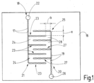
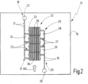
- the first electrode 18 and the second electrode 20 are in some embodiments ( Figures 1-4 , 8 , 10 ) interdigitally arranged.
- the first electrode 18 has a first base zone 21, which extends from a first terminal 22, for example in a straight line. Transversely and preferably at right angles from the first base zone 21 protrude a plurality of first electrode fingers 23.
- the first electrode fingers 23 are arranged parallel to one another at equal distances. Between two immediately adjacent first electrode fingers 23, a first A gap 24 is formed.
- the number of first electrode fingers 23 and thus the number of first gaps 24 can vary depending on the realized size of the sensor.
- the length of the base zone 21 or the length of the first electrode fingers 23 can also vary. In the exemplary embodiment, all first electrode fingers 23 are of the same length.
- the second electrode which is made from the at least one second thread 19, is constructed analogously to the first electrode 18. It has a second base zone 25, which extends away from a second connection 26, for example in a straight line.
- the first base zone 21 and the second base zone 25 preferably run parallel to one another and are arranged at a distance from one another.
- a plurality of second electrode fingers 27 protrude transversely and preferably at right angles from the second base zone 25.
- the second electrode fingers 27 are arranged parallel to one another and at equal distances from one another. They are preferably of equal length.
- a second intermediate space 28 is formed between each two immediately adjacent second electrode fingers 27.
- Threads made of different materials can be used for embroidering the base zones 21, 25 and the electrode fingers 23, 27.
- the first electrode 18 can be embroidered from two different (in particular differently conductive) first threads
- the second electrode 20 can be embroidered from two different (in particular differently conductive) second threads.
- first electrode fingers 23 and the second electrode fingers 27 are arranged parallel to one another. At least one, and, for example, exactly one, second electrode finger 27 protrudes into one, several, or all of the first intermediate spaces 24. At least one, and, for example, exactly one, first electrode finger 23 protrudes into one, several, or all of the second intermediate spaces 28. Therefore, a first electrode finger 23 and a second electrode finger 27 are always arranged alternately in a direction parallel to the extension of the first base zone 21 and the second base zone 25.
- a distance exists between the first electrode 18 and the second electrode 20, so that the at least one first thread 17 and the at least one second thread 19 do not directly touch one another.
- a first distance a exists between each first electrode finger 23 and an immediately adjacent second electrode finger 27, viewed parallel to the direction of extension of the base zones 21, 25.
- a second distance b exists between the free end of the first electrode fingers 23 and the second base zone 25. Accordingly, the same second distance b can exist between the free end of the second electrode fingers 27.
- the first distance a and the second distance b are of equal magnitude.
- the carrier 16 is, at least in the area in which the electrodes 18, 20 are arranged, electrically non-conductive or at least not designed in such a way that it creates an indirect electrical contact between the two electrodes.
- An indirect contact and an indirect electrically conductive connection between the first electrode 18 and the second electrode 20 can be established via a cover layer 32.
- the cover layer 32 is formed by stitching at least one third thread 33 onto the carrier 16.
- the at least one third thread has electrically conductive components and can have a structure as described above in connection with the first thread 17.
- the at least one third thread 33 is different from the at least one first thread 17 and the at least one second thread 19.
- the electrical conductivity of the at least one third thread 33 is different from the electrical conductivity of the threads 17, 19 of the electrodes 18, 20.
- the electrical conductivity of the at least one third thread 33 - at least in a state in which no external force acts on the at least one third thread 33 - is smaller than the electrical conductivity of the first thread 17 and the second thread 19.
- the at least one third thread 33 has electrically conductive components, such as fillers and/or fibers and/or filaments, the spacing of which changes upon external influence, whereby the conductivity of the at least one third thread 33 is changed and preferably increases.
- the at least one third thread 33 overlaps the first electrode 18 and the second electrode 20 at several Places and thereby forms a plurality of first contact points 34 with the at least one first thread 17 and a plurality of second contact points 35 with the at least one second thread 19.
- Each first contact point 34 has a first contact resistance R1 between the first thread 17 and the third thread 33 and each second contact point 35 has a second contact resistance R2 between the second thread 19 and the third thread 33.
- the at least one third thread 33 can have a variable contact resistance R3.
- the contact between the at least one third thread 33 and the at least one first thread 17 or the at least one second thread 19 can be improved, so that the first contact resistance R1 and the second contact resistance R2 become smaller.
- the contact resistance R3 of the third thread 33 can also be reduced by the action of the force, for example by electrically conductive components of the third thread 33 establishing a better electrical connection with one another along the extent of the third thread 33 due to the acting force F, whereby its conductivity is increased or its contact resistance R3 between a first contact point 34 and an immediately adjacent second contact point 35 is reduced.
- the at least one third thread 33 of the cover layer 32 forms, by stitching onto the carrier 16, a plurality of stitches, which are referred to as bridging stitches 36, each having a first contact point 34 and a second Contact point 35, and in the exemplary embodiment, each of which overlaps a first electrode finger 23 and an immediately adjacent second electrode finger 27. It is preferred if each bridging stitch 36 overlaps exactly one first electrode finger 23 and exactly one second electrode finger 27. As a result, a bridging stitch 36 can be kept very short between its two puncture points 37.
- a bridging stitch 36 between two puncture points 37 is shown schematically in the Figures 5 and 6 illustrated.
- the Figures 2 to 4 show different embroidery patterns that can be used to arrange the bridging stitches 36 of the cover layer 32.
- each first electrode finger 23 is assigned exactly one second electrode finger 27, which form a common electrode finger pair.
- An electrode finger pair 23, 27 is overlapped by a bridging stitch group consisting of several bridging stitches 36.
- Bridging stitches 36 that connect electrode fingers of different electrode finger pairs to one another are not present.
- the bridging stitches 36 assigned to a common electrode finger pair 23, 27 are arranged such that the puncture points 37 are aligned along two parallel lines, these lines extending parallel to the electrode fingers 23, 27 of the electrode finger pair.
- the bridging stitches 36 thus each form a bridging stitch group for a pair of electrode fingers, wherein the bridging stitch groups do not overlap in a direction parallel to the direction of extension of the base zones 21, 25 and are connected to one another either with contact or with a distance.
- the bridging stitches 36 are arranged offset from one another parallel to the direction of extension of the base zones 21, 25.
- a first electrode finger 23, which projects into a second intermediate space 28 is coupled by a plurality of bridging stitches 36 to the one immediately adjacent second electrode finger 27 and by a plurality of other bridging stitches 36 to the other immediately adjacent second electrode finger 27.
- the electrical connection between the first electrode 18 and the second electrode 20 can be improved by the cover layer 32, at least when an external force F is applied.
- the embroidery density of the bridging stitches 36 can vary.
- Each bridging stitch 36 has at least one puncture point 37 located in a first intermediate space 24 and a second intermediate space 28. All puncture points 37 are arranged adjacent to the respective electrode fingers 23, 27 and do not penetrate the at least one first thread 17 or the at least one second thread 19.
- the cover layer 32 is viewed in the direction of extension of the electrode fingers 23, 27, in some embodiments ( Figures 1-4 , 8 and 10 ) is limited to the area between the first base zone 21 and the second base zone 25.
- the third thread 33 preferably overlaps neither the first base zone 21 nor the second base zone 25.
- the first contact points 34 and the second contact points 35 are present exclusively on the electrode fingers 23 and 27, respectively, at which the at least one third thread 33 overlaps the electrodes 18, 20.
- Figure 7 1 schematically illustrates an electrical equivalent circuit for a resistor between a first thread 17 and a second thread 19, which are connected to one another via exactly one first contact point 34 and exactly one second contact point 35 by a single bridging stitch 36.
- This resistor is formed by the series connection of the first contact resistor R1, the contact resistor R3, and the second contact resistor R2.
- the values of all individual resistors R1, R3, R2 in this series connection, but at least the values of the two contact resistors R1, R2, can be changed depending on the acting force F.
- the action of the force F can be generated, for example, by pressing with the tip of a finger 38 on the cover layer 32.
- the force F generally acts not only on a single bridging stitch 36 of the cover layer 32, but on a plurality of bridging stitches 36.
- several series circuits of a first contact resistance R1, a contact resistance R3 and a second contact resistance R2, as shown in Figure 7 is schematically illustrated, connected in parallel by acting on the plurality of bridging stubs 36.
- a total resistance RG results between the first terminal 22 and the second terminal 26 by the parallel connection of several series circuits, one of which is schematically shown with Figure 7 is illustrated.
- the total resistance RG is determined even without the action of an external force F by a plurality of parallel series circuits 39 according to Figure 7 formed when an electrically conductive connection between the two electrodes 18, 20 is already established by the cover layer 32 without the action of an external force F, the total resistance RG of which can be changed and in particular reduced by the action of the force F.
- the at least one spacer thread 45 or a spacer thread bundle of a plurality of spacer threads 45 is used, the total thickness of which is greater than the total thickness of the fiber bundles of first threads 17 or second threads 19.
- a sensor 15 can also be manufactured, which represents a potentiometer 46 ( Figure 10).
- the potentiometer 46 at least one base zone, and for example the first base zone 21, is designed as a resistance zone 47.
- the resistance zone 47 has a lower conductivity than the remaining parts of the first electrode 18. This can be achieved, for example, by stitching the resistance zone 47 from a thread that has a lower conductivity than the thread used to stitch the first electrode fingers 23.
- a third connection 48 is electrically connected to the resistance zone 47. Between the first connection 22 and the third connection 48, a maximum potentiometer resistance provided by the resistance zone 47 is thus formed.
- the first electrode fingers 23 extend at different locations in the resistance zone 47.
- the second electrode 20 is designed analogously to the embodiments described above.
- a first voltage U1 is applied between the first terminal 22 and the third terminal 48
- a second voltage U2 can be measured between the second terminal 26 and the third terminal 48, which second voltage U2 depends on the position of the point of action 49 in the direction of extension E.
- U 1 R max U 2 R max ⁇ RG
- the invention relates to a sensor 15 which is produced by stitching threads 17, 19, 33 onto a carrier 16.
- a first electrode 18, a second electrode 20, and a cover layer 32 are formed.
- An electrically conductive connection between the first electrode 18 and the second electrode 20 can be established via the cover layer 32, at least when a force F acts on the cover layer 32 and presses at least a portion of the cover layer 32 against a portion of the first electrode 18 and the second electrode 20.
- This force F can be caused by pressure exerted locally on the cover layer 32 and/or by bending the cover layer 32 or the carrier 16.
- the entire sensor 15, and in particular the first electrode 18, the second electrode 20, and the cover layer 32 are manufactured exclusively by stitching onto a common carrier 16.
- the sensor is particularly simple and cost-effective to manufacture and is robust.
- the invention also allows for very flat sensors 20.
- the material used to manufacture the sensor 15 is low, and only a small amount of waste is generated during production.
- the measuring range and the measuring sensitivity of the sensor 15 can be selected by selecting the thread or yarn or twist for the first thread and/or the second thread and/or the third thread.
- the measuring range and the measuring sensitivity can also be varied by the arrangement of the electrodes 18, 20 and/or the bridging stitches 36 of the cover layer 32.
- any other shapes for forming the electrodes 18, 20 are also possible.
- the electrode fingers 23, 27 can also have at least one curvature and/or at least one kink.
- the base zones 21, 25 do not necessarily have to run in a straight line, but can also have at least one curvature and/or at least one kink.
- the base zones 21, 25 can also enclose or occupy a surface, for example, a circular or polygonal surface.
- the sensor according to the invention can also be produced with one or more further embroidered sensors in a common process on a sewing machine or embroidery machine, for example, with another sensor according to the invention or a humidity sensor.
- the sensor according to the invention can also be combined with other embroidered electrical functional areas, such as supply lines and/or heaters, during embroidery.
Landscapes
- Engineering & Computer Science (AREA)
- Physics & Mathematics (AREA)
- General Physics & Mathematics (AREA)
- Mechanical Engineering (AREA)
- Textile Engineering (AREA)
- Force Measurement Appropriate To Specific Purposes (AREA)
Claims (13)
- Capteur (15) qui est conçu pour détecter et/ou mesurer une force (F) agissant sur le capteur (15), ledit capteur (15) comprenant :- un support (16),- une première électrode (18) qui est constituée d'au moins un premier fil (17) brodé sur le support (16) et présentant des composants électriquement conducteurs,- une deuxième électrode (20) qui est constituée d'au moins un deuxième fil (19) brodé sur le support (16) et présentant des composants électriquement conducteurs, les deux électrodes (18, 20) étant disposées à distance l'une de l'autre sur le support (16),- une couche de recouvrement (32) qui est constituée d'au moins un troisième fil (33) brodé sur le support (16) et présentant des composants électriquement conducteurs, le troisième fil (33), au nombre d'au moins un, de la couche de recouvrement (32) étant appliqué en plusieurs emplacements de contact (34, 35) contre le premier fil (17), au nombre d'au moins un, de la première électrode (18) et contre le deuxième fil (19), au nombre d'au moins un, de la deuxième électrode (20),caractérisé en ce que la première électrode (18) présente une première zone de base (21) et plusieurs premiers doigts d'électrode (23) s'étendant à partir de la première zone de base (21), sachant qu'entre deux premiers doigts d'électrode (23) directement adjacents, est formé respectivement un premier espace intermédiaire (24), en ce que la deuxième électrode (20) présente une deuxième zone de base (25) et plusieurs deuxièmes doigts d'électrode (27) s'étendant à partir de la deuxième zone de base (25), sachant qu'entre deux deuxièmes doigts d'électrode (27) directement adjacents, est formé respectivement un deuxième espace intermédiaire (28).
- Capteur selon la revendication 1, caractérisé en ce qu'il est prévu sur le support (16) et/ou au niveau du support (16), à coté des électrodes (18, 20), au moins un élément d'espacement qui prédéfinit l'espacement entre le support (16) et la couche de recouvrement (32).
- Capteur selon la revendication 2, caractérisé en ce que l'élément d'espacement, au nombre d'au moins un, est constitué d'un fil d'espacement (45) qui est cousu ou brodé sur le support (16).
- Capteur selon une des revendications précédentes, caractérisé en ce que le capteur (15) présente une résistance totale (RG) entre une première borne (22) de la première électrode (18) et une deuxième borne (26) de la deuxième électrode (20), dont la valeur est fonction d'une force (F) agissant sur la couche de recouvrement (32).
- Capteur selon la revendication 4, caractérisé en ce que la résistance totale (RG) est fonction d'une première résistance de contact (R1) entre le premier fil (17), au nombre d'au moins un, de la première électrode (18) et le troisième fil (33), au nombre d'au moins un, de la couche de recouvrement (32), et d'une deuxième résistance de contact (R2) entre le deuxième fil (19), au nombre d'au moins un, de la deuxième électrode (20) et le troisième fil (33), au nombre d'au moins un, de la couche de recouvrement (32).
- Capteur selon la revendication 4 ou 5, caractérisé en ce que la résistance totale (RG) est fonction d'une résistance de passage (R3) du troisième fil (33), au nombre d'au moins un, dont la valeur dépend d'une force (F) agissant sur le troisième fil, au nombre d'au moins un, de la couche de recouvrement (32).
- Capteur selon une des revendications précédentes, caractérisé en ce qu'au moins un deuxième doigt d'électrode (27) avance dans un premier espace intermédiaire (24), et en ce qu'au moins un premier doigt d'électrode (23) avance dans un deuxième espace intermédiaire (28).
- Capteur selon une des revendications précédentes, caractérisé en ce que plusieurs points de piquage (37) de la couche de recouvrement (32) brodée, auxquels le troisième fil (33), au nombre d'au moins un, pique dans le support (16), sont disposés dans les premiers et/ou deuxièmes espaces intermédiaires (24, 28).
- Capteur selon la revendication 8, caractérisé en ce que le troisième fil (33), au nombre d'au moins un, de la couche de recouvrement (32) présente plusieurs points de franchissement (36) qui passent respectivement au-dessus de l'un des premiers doigts d'électrode (23) et de l'un des deuxièmes doigts d'électrode (27).
- Capteur selon la revendication 9, caractérisé en ce que quelques-uns des points de franchissement (36), qui passent au-dessus de l'un des premiers doigts d'électrode (23), passent au-dessus d'un doigt parmi deux deuxièmes doigts d'électrode (27) directement adjacents, et d'autres points parmi les points de franchissement (36) qui passent au-dessus de ce premier doigt d'électrode (23) passent au-dessus de l'autre doigt des deux deuxièmes doigts d'électrode (27) directement adjacents.
- Capteur selon une des revendications précédentes, caractérisé en ce que le troisième fil (33), au nombre d'au moins un, de la couche de recouvrement (32) passe au-dessus du premier fil (17), au nombre d'au moins un, et du deuxième fil (19), au nombre d'au moins un, au moins en majeure partie au niveau des doigts d'électrode (23, 27).
- Capteur selon une des revendications précédentes, caractérisé en ce que le capteur (15) est réalisé sous forme de potentiomètre (47).
- Capteur selon la revendication 12, caractérisé en ce que la première zone de base (21) de la première électrode (18) ou la deuxième zone de base (25) de la deuxième électrode (20) constitue une zone de résistance (47), et en ce que le capteur (15) présente une résistance totale (RG) entre une première borne (22) de la première électrode (18) et une deuxième borne (26) de la deuxième électrode (20), la résistance totale (RG) variant en fonction de l'endroit où une force (F) agit sur la couche de recouvrement (32).
Applications Claiming Priority (2)
| Application Number | Priority Date | Filing Date | Title |
|---|---|---|---|
| DE102019120191.8A DE102019120191B3 (de) | 2019-07-25 | 2019-07-25 | Gestickter Sensor |
| PCT/EP2020/070768 WO2021013918A1 (fr) | 2019-07-25 | 2020-07-23 | Capteur brodé |
Publications (3)
| Publication Number | Publication Date |
|---|---|
| EP4004510A1 EP4004510A1 (fr) | 2022-06-01 |
| EP4004510C0 EP4004510C0 (fr) | 2025-03-26 |
| EP4004510B1 true EP4004510B1 (fr) | 2025-03-26 |
Family
ID=71786943
Family Applications (1)
| Application Number | Title | Priority Date | Filing Date |
|---|---|---|---|
| EP20746164.1A Active EP4004510B1 (fr) | 2019-07-25 | 2020-07-23 | Capteur brodé |
Country Status (5)
| Country | Link |
|---|---|
| US (1) | US12092535B2 (fr) |
| EP (1) | EP4004510B1 (fr) |
| JP (1) | JP7674333B2 (fr) |
| DE (1) | DE102019120191B3 (fr) |
| WO (1) | WO2021013918A1 (fr) |
Families Citing this family (3)
| Publication number | Priority date | Publication date | Assignee | Title |
|---|---|---|---|---|
| KR102318554B1 (ko) * | 2019-09-03 | 2021-10-29 | 한국전자기술연구원 | 압력센서 |
| TWI781403B (zh) * | 2020-05-14 | 2022-10-21 | 美宸科技股份有限公司 | 織物型應變計、織物型壓力計與智慧型衣物 |
| CN113739961A (zh) * | 2020-05-28 | 2021-12-03 | 纳米及先进材料研发院有限公司 | 柔性压力传感器阵列及其制造方法 |
Family Cites Families (18)
| Publication number | Priority date | Publication date | Assignee | Title |
|---|---|---|---|---|
| GB2343516A (en) | 1998-11-03 | 2000-05-10 | Univ Brunel | Fabric pressure sensor comprising conductive layers or strips and an insulating separator |
| WO2001075778A1 (fr) * | 2000-04-03 | 2001-10-11 | Brunel University | Textile electro-conducteur pressosensible |
| GB0011829D0 (en) * | 2000-05-18 | 2000-07-05 | Lussey David | Flexible switching devices |
| WO2002087929A1 (fr) * | 2001-04-27 | 2002-11-07 | Gorix Ltd | Capteur |
| DE102005055842A1 (de) * | 2005-11-23 | 2007-05-24 | Alpha-Fit Gmbh | Drucksensor |
| EP1997952B1 (fr) * | 2007-05-29 | 2013-08-07 | Textilforschungsinstitut Thüringen-Vogtland e.V. | Structure textile pour le stockage transdermique d'une matière active |
| WO2009017362A2 (fr) * | 2007-07-31 | 2009-02-05 | Seoul National University Industry Foundation | Fil de broderie composite, métallique, électroconducteur et circuit brodé utilisant ledit fil |
| KR100966842B1 (ko) * | 2008-02-26 | 2010-06-29 | 한국생산기술연구원 | 자수 기술을 이용한 디지털 가먼트 및 그 제조 방법 |
| US8161826B1 (en) * | 2009-03-05 | 2012-04-24 | Stryker Corporation | Elastically stretchable fabric force sensor arrays and methods of making |
| US8904876B2 (en) * | 2012-09-29 | 2014-12-09 | Stryker Corporation | Flexible piezocapacitive and piezoresistive force and pressure sensors |
| DE102013001772A1 (de) * | 2013-01-31 | 2014-07-31 | Audi Ag | Flexibler Oberflächenbezug zum Beziehen einer Vorrichtung im Innenraum eines Kraftfahrzeugs |
| CN203719797U (zh) | 2013-12-24 | 2014-07-16 | 北方工业大学 | 一种压电式压力传感器 |
| US9588625B2 (en) * | 2014-08-15 | 2017-03-07 | Google Inc. | Interactive textiles |
| US10082913B2 (en) * | 2015-05-10 | 2018-09-25 | Microsoft Technology Licensing, Llc | Embroidered sensor assembly |
| US9816799B2 (en) * | 2015-12-18 | 2017-11-14 | Oculus Vr, Llc | Embroidered strain sensing elements |
| US10054503B2 (en) * | 2016-03-11 | 2018-08-21 | Microsoft Technology Licensing, Llc | Force sensor |
| DE102016106071A1 (de) * | 2016-04-04 | 2017-10-05 | Pilz Gmbh & Co. Kg | Gewebe mit mehreren Gewebelagen und Verfahren zu dessen Herstellung |
| CN106948065B (zh) | 2017-02-21 | 2018-03-16 | 嘉兴学院 | 具有发电功能的织物结构 |
-
2019
- 2019-07-25 DE DE102019120191.8A patent/DE102019120191B3/de active Active
-
2020
- 2020-07-23 US US17/629,903 patent/US12092535B2/en active Active
- 2020-07-23 JP JP2022504287A patent/JP7674333B2/ja active Active
- 2020-07-23 EP EP20746164.1A patent/EP4004510B1/fr active Active
- 2020-07-23 WO PCT/EP2020/070768 patent/WO2021013918A1/fr not_active Ceased
Also Published As
| Publication number | Publication date |
|---|---|
| EP4004510A1 (fr) | 2022-06-01 |
| EP4004510C0 (fr) | 2025-03-26 |
| US20220252472A1 (en) | 2022-08-11 |
| JP7674333B2 (ja) | 2025-05-09 |
| JP2022541623A (ja) | 2022-09-26 |
| DE102019120191B3 (de) | 2020-12-24 |
| WO2021013918A1 (fr) | 2021-01-28 |
| US12092535B2 (en) | 2024-09-17 |
Similar Documents
| Publication | Publication Date | Title |
|---|---|---|
| DE60030525T2 (de) | Positionssensor zum Bestimmen der Position einer mechanischen Interaktion | |
| EP3440444B1 (fr) | Tissu comportant plusieurs couches de tissu | |
| EP3032999B1 (fr) | Électrode capacitive textile et procédé de fabrication de ladite électrode | |
| DE60218749T2 (de) | Folientastatur | |
| EP3440249B1 (fr) | Textile intelligent doté de capteurs, multicouche et procédé de fabrication | |
| DE60111510T2 (de) | Mit elektrischem, leitfähigem gewebe gebildeter detektor | |
| EP4004510B1 (fr) | Capteur brodé | |
| EP1771611B1 (fr) | Tricot a conductivite electrique biaxiale | |
| EP3298921B1 (fr) | Semelle intérieure de chaussure ou semelle de chaussure | |
| WO2008011739A1 (fr) | Étiquette rfid | |
| DE102011051913A1 (de) | Insassenerfassungssensor und Verfahren zum Herstellen desselben | |
| WO2018193135A1 (fr) | Orthèse en tricot et utilisation d'une orthèse en tricot | |
| EP2964818B1 (fr) | Base de garniture de carde | |
| EP3714089B1 (fr) | Article tricoté et procédé pour son obtention | |
| DE102019118887A1 (de) | Verfahren zum Erzeugen einer Druckerfassungsvorrichtung, Druckerfassungsvorrichtung sowie Handschuh | |
| WO2012072240A1 (fr) | Support de données portable | |
| WO2020064648A1 (fr) | Ensemble capteur | |
| DE19510617A1 (de) | Flexible Kontaktmatte | |
| EP4092692B1 (fr) | Procédé d'établissement d'une connexion entre une électrode et un conducteur électrique | |
| DE102017206156B4 (de) | Betätigungsvorrichtung, Verfahren zur Herstellung einer Betätigungsvorrichtung, und damit ausgestattete Anordnung | |
| WO2013037074A1 (fr) | Garniture pour couvercle d'une carde | |
| DE202020101108U1 (de) | Textilbasierter elektrischer Leiter |
Legal Events
| Date | Code | Title | Description |
|---|---|---|---|
| STAA | Information on the status of an ep patent application or granted ep patent |
Free format text: STATUS: UNKNOWN |
|
| STAA | Information on the status of an ep patent application or granted ep patent |
Free format text: STATUS: THE INTERNATIONAL PUBLICATION HAS BEEN MADE |
|
| PUAI | Public reference made under article 153(3) epc to a published international application that has entered the european phase |
Free format text: ORIGINAL CODE: 0009012 |
|
| STAA | Information on the status of an ep patent application or granted ep patent |
Free format text: STATUS: REQUEST FOR EXAMINATION WAS MADE |
|
| 17P | Request for examination filed |
Effective date: 20220208 |
|
| AK | Designated contracting states |
Kind code of ref document: A1 Designated state(s): AL AT BE BG CH CY CZ DE DK EE ES FI FR GB GR HR HU IE IS IT LI LT LU LV MC MK MT NL NO PL PT RO RS SE SI SK SM TR |
|
| DAV | Request for validation of the european patent (deleted) | ||
| DAX | Request for extension of the european patent (deleted) | ||
| GRAP | Despatch of communication of intention to grant a patent |
Free format text: ORIGINAL CODE: EPIDOSNIGR1 |
|
| STAA | Information on the status of an ep patent application or granted ep patent |
Free format text: STATUS: GRANT OF PATENT IS INTENDED |
|
| INTG | Intention to grant announced |
Effective date: 20241111 |
|
| GRAS | Grant fee paid |
Free format text: ORIGINAL CODE: EPIDOSNIGR3 |
|
| GRAA | (expected) grant |
Free format text: ORIGINAL CODE: 0009210 |
|
| STAA | Information on the status of an ep patent application or granted ep patent |
Free format text: STATUS: THE PATENT HAS BEEN GRANTED |
|
| AK | Designated contracting states |
Kind code of ref document: B1 Designated state(s): AL AT BE BG CH CY CZ DE DK EE ES FI FR GB GR HR HU IE IS IT LI LT LU LV MC MK MT NL NO PL PT RO RS SE SI SK SM TR |
|
| REG | Reference to a national code |
Ref country code: GB Ref legal event code: FG4D Free format text: NOT ENGLISH |
|
| REG | Reference to a national code |
Ref country code: CH Ref legal event code: EP |
|
| REG | Reference to a national code |
Ref country code: DE Ref legal event code: R096 Ref document number: 502020010694 Country of ref document: DE |
|
| REG | Reference to a national code |
Ref country code: IE Ref legal event code: FG4D Free format text: LANGUAGE OF EP DOCUMENT: GERMAN |
|
| U01 | Request for unitary effect filed |
Effective date: 20250417 |
|
| U07 | Unitary effect registered |
Designated state(s): AT BE BG DE DK EE FI FR IT LT LU LV MT NL PT RO SE SI Effective date: 20250425 |
|
| PG25 | Lapsed in a contracting state [announced via postgrant information from national office to epo] |
Ref country code: RS Free format text: LAPSE BECAUSE OF FAILURE TO SUBMIT A TRANSLATION OF THE DESCRIPTION OR TO PAY THE FEE WITHIN THE PRESCRIBED TIME-LIMIT Effective date: 20250626 |
|
| PG25 | Lapsed in a contracting state [announced via postgrant information from national office to epo] |
Ref country code: NO Free format text: LAPSE BECAUSE OF FAILURE TO SUBMIT A TRANSLATION OF THE DESCRIPTION OR TO PAY THE FEE WITHIN THE PRESCRIBED TIME-LIMIT Effective date: 20250626 |
|
| PG25 | Lapsed in a contracting state [announced via postgrant information from national office to epo] |
Ref country code: HR Free format text: LAPSE BECAUSE OF FAILURE TO SUBMIT A TRANSLATION OF THE DESCRIPTION OR TO PAY THE FEE WITHIN THE PRESCRIBED TIME-LIMIT Effective date: 20250326 |
|
| PG25 | Lapsed in a contracting state [announced via postgrant information from national office to epo] |
Ref country code: GR Free format text: LAPSE BECAUSE OF FAILURE TO SUBMIT A TRANSLATION OF THE DESCRIPTION OR TO PAY THE FEE WITHIN THE PRESCRIBED TIME-LIMIT Effective date: 20250627 |
|
| U20 | Renewal fee for the european patent with unitary effect paid |
Year of fee payment: 6 Effective date: 20250627 |
|
| PG25 | Lapsed in a contracting state [announced via postgrant information from national office to epo] |
Ref country code: SM Free format text: LAPSE BECAUSE OF FAILURE TO SUBMIT A TRANSLATION OF THE DESCRIPTION OR TO PAY THE FEE WITHIN THE PRESCRIBED TIME-LIMIT Effective date: 20250326 |
|
| PG25 | Lapsed in a contracting state [announced via postgrant information from national office to epo] |
Ref country code: ES Free format text: LAPSE BECAUSE OF FAILURE TO SUBMIT A TRANSLATION OF THE DESCRIPTION OR TO PAY THE FEE WITHIN THE PRESCRIBED TIME-LIMIT Effective date: 20250326 |
|
| PG25 | Lapsed in a contracting state [announced via postgrant information from national office to epo] |
Ref country code: PL Free format text: LAPSE BECAUSE OF FAILURE TO SUBMIT A TRANSLATION OF THE DESCRIPTION OR TO PAY THE FEE WITHIN THE PRESCRIBED TIME-LIMIT Effective date: 20250326 |
|
| PG25 | Lapsed in a contracting state [announced via postgrant information from national office to epo] |
Ref country code: SK Free format text: LAPSE BECAUSE OF FAILURE TO SUBMIT A TRANSLATION OF THE DESCRIPTION OR TO PAY THE FEE WITHIN THE PRESCRIBED TIME-LIMIT Effective date: 20250326 |
|
| PG25 | Lapsed in a contracting state [announced via postgrant information from national office to epo] |
Ref country code: IS Free format text: LAPSE BECAUSE OF FAILURE TO SUBMIT A TRANSLATION OF THE DESCRIPTION OR TO PAY THE FEE WITHIN THE PRESCRIBED TIME-LIMIT Effective date: 20250726 |
|
| PG25 | Lapsed in a contracting state [announced via postgrant information from national office to epo] |
Ref country code: CZ Free format text: LAPSE BECAUSE OF FAILURE TO SUBMIT A TRANSLATION OF THE DESCRIPTION OR TO PAY THE FEE WITHIN THE PRESCRIBED TIME-LIMIT Effective date: 20250326 |
|
| PLBE | No opposition filed within time limit |
Free format text: ORIGINAL CODE: 0009261 |
|
| STAA | Information on the status of an ep patent application or granted ep patent |
Free format text: STATUS: NO OPPOSITION FILED WITHIN TIME LIMIT |
|
| REG | Reference to a national code |
Ref country code: CH Ref legal event code: L10 Free format text: ST27 STATUS EVENT CODE: U-0-0-L10-L00 (AS PROVIDED BY THE NATIONAL OFFICE) Effective date: 20260211 |
|
| REG | Reference to a national code |
Ref country code: CH Ref legal event code: H13 Free format text: ST27 STATUS EVENT CODE: U-0-0-H10-H13 (AS PROVIDED BY THE NATIONAL OFFICE) Effective date: 20260224 |
|
| 26N | No opposition filed |
Effective date: 20260105 |
|
| GBPC | Gb: european patent ceased through non-payment of renewal fee |
Effective date: 20250723 |
|
| PG25 | Lapsed in a contracting state [announced via postgrant information from national office to epo] |
Ref country code: GB Free format text: LAPSE BECAUSE OF NON-PAYMENT OF DUE FEES Effective date: 20250723 |
|
| PG25 | Lapsed in a contracting state [announced via postgrant information from national office to epo] |
Ref country code: CH Free format text: LAPSE BECAUSE OF NON-PAYMENT OF DUE FEES Effective date: 20250731 |