EP3299575A2 - Bohrlochabschlusssystem und verfahren - Google Patents
Bohrlochabschlusssystem und verfahren Download PDFInfo
- Publication number
- EP3299575A2 EP3299575A2 EP18154379.4A EP18154379A EP3299575A2 EP 3299575 A2 EP3299575 A2 EP 3299575A2 EP 18154379 A EP18154379 A EP 18154379A EP 3299575 A2 EP3299575 A2 EP 3299575A2
- Authority
- EP
- European Patent Office
- Prior art keywords
- expandable metal
- completion system
- casing
- downhole completion
- downhole
- Prior art date
- Legal status (The legal status is an assumption and is not a legal conclusion. Google has not performed a legal analysis and makes no representation as to the accuracy of the status listed.)
- Withdrawn
Links
Images




Classifications
-
- E—FIXED CONSTRUCTIONS
- E21—EARTH OR ROCK DRILLING; MINING
- E21B—EARTH OR ROCK DRILLING; OBTAINING OIL, GAS, WATER, SOLUBLE OR MELTABLE MATERIALS OR A SLURRY OF MINERALS FROM WELLS
- E21B43/00—Methods or apparatus for obtaining oil, gas, water, soluble or meltable materials or a slurry of minerals from wells
- E21B43/02—Subsoil filtering
- E21B43/10—Setting of casings, screens, liners or the like in wells
- E21B43/103—Setting of casings, screens, liners or the like in wells of expandable casings, screens, liners, or the like
-
- E—FIXED CONSTRUCTIONS
- E21—EARTH OR ROCK DRILLING; MINING
- E21B—EARTH OR ROCK DRILLING; OBTAINING OIL, GAS, WATER, SOLUBLE OR MELTABLE MATERIALS OR A SLURRY OF MINERALS FROM WELLS
- E21B33/00—Sealing or packing boreholes or wells
- E21B33/10—Sealing or packing boreholes or wells in the borehole
- E21B33/12—Packers; Plugs
- E21B33/124—Units with longitudinally-spaced plugs for isolating the intermediate space
- E21B33/1243—Units with longitudinally-spaced plugs for isolating the intermediate space with inflatable sleeves
-
- E—FIXED CONSTRUCTIONS
- E21—EARTH OR ROCK DRILLING; MINING
- E21B—EARTH OR ROCK DRILLING; OBTAINING OIL, GAS, WATER, SOLUBLE OR MELTABLE MATERIALS OR A SLURRY OF MINERALS FROM WELLS
- E21B33/00—Sealing or packing boreholes or wells
- E21B33/10—Sealing or packing boreholes or wells in the borehole
- E21B33/12—Packers; Plugs
- E21B33/127—Packers; Plugs with inflatable sleeve
- E21B33/1277—Packers; Plugs with inflatable sleeve characterised by the construction or fixation of the sleeve
Definitions
- the present invention relates to a downhole completion system for being arranged in a wellbore, comprising several casing sections having a casing length of 10-14 metres mounted as one well tubular metal structure by means of casing collars.
- the present invention also relates to a downhole method for completing a well having a wellbore.
- annular barriers are positioned at predetermined positions for providing zone isolation between different zones, for instance between a non-producing zone and a production zone. However, if the annular barriers are positioned incorrectly, they may isolate inaccurately which results in the well not producing as intended.
- a downhole completion system for being arranged in a wellbore, comprising several casing sections having a casing length of 10-14 metres mounted as one well tubular metal structure by means of casing collars, wherein a number of the several casing sections each comprises at least three annular barriers each comprising an expandable metal sleeve configured to be expanded to abut the wellbore, the annular barriers of each casing section having a common longitudinal extension of at least 50% of the casing length.
- At least one of the expanded metal sleeves may have a plurality of perforations.
- each section may have a first end part and a second end part, at least the first end part may having at least 1 metre which is free from annular ba rriers.
- the annular barriers may be arranged with a mutual distance of less than 100 cm, preferably less than 50 cm.
- each annular barrier may have a barrier length of 1-2.5 metres.
- each casing section may have a base pipe.
- Each of the expandable metal sleeves may surround and may fasten to the same base pipe, forming an annular space between each expandable metal sleeve and the base pipe.
- each space may comprise at least one thermally decomposable compound, which compound is thermally decomposable below a temperature of 400°C and is adapted to generate gas or super-critical fluid upon decomposition.
- the compound may comprise nitrogen.
- the compound may be selected from a group consisting of: ammonium dichromate, ammonium nitrate, ammonium nitrite, barium azide, sodium nitrate or a combination thereof.
- the compound may decompose at temperatures above 100°C, preferably above 180°C.
- the annular space is pre-pressurised to a pressure above 5 bar, preferably above 50 bar and more preferably above 100 bar, even more preferably above 250 bar.
- the compound may be present in the form of a powder, a powder dispersed in a liquid or a powder dissolved in a liquid.
- the base pipe may have at least one opening opposite each of the expandable metal sleeves for expanding the expandable metal sleeves by allowing pressurised fluid to enter the openings.
- the annular barriers may comprise a valve in fluid communication with the openings.
- the expandable metal sleeves may be fastened to the base pipe by means of welding, crimping or connection parts connecting the expandable metal sleeves to the base pipe.
- the expandable metal sleeves of each casing section may be connected to form part of the base pipe, so that an inner face of the expandable metal sleeves forms part of an inner face of the base pipe.
- the expandable metal sleeves of each casing section may be connected directly or indirectly, forming a connection area.
- each casing section may be connected indirectly by means of a tubular connection part.
- each casing section may be connected directly end to end in an overlapping manner.
- the downhole completion system may further comprise a patch to be expanded inside the casing section, so that each end of the patch overlaps the connection area.
- each expandable metal sleeve may comprise a plurality of sealing elements.
- each expandable metal sleeve may comprise sections having an increased thickness, which sections are expanded less than other sections of the expandable metal sleeve.
- a number of the several casing sections may each comprise at least four or five annular barriers.
- sealing elements may comprise key rings, coiled springs or a combination thereof.
- the present invention also relates to a downhole method for completing a well having a wellbore, comprising:
- the expansion of the expandable metal sleeves of the annular barriers may be performed sequentially.
- the downhole method may further comprise perforating at least one of the expandable metal sleeves, creating access of reservoir fluid into the casing sections and into the well tubular metal structure.
- the downhole method may further comprise expanding a patch inside the well tubular metal structure opposite the perforated expandable metal sleeve for sealing off the perforations.
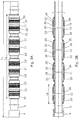
- Fig. 1 shows a downhole completion system 100 arranged in a wellbore 2 of a well 5.
- the downhole completion system 100 comprises several casing sections 3 having a casing length of 10-14 metres which is a standard length, so that the casing section, also called casing joints, can fit into the conventional rig equipment when mounting the well tubular metal structure 1 and lowering the well tubular metal structure into the wellbore.
- the several casing sections 3 are mounted as one well tubular metal structure 1 by means of casing collars 4.
- a number of the several casing sections 3 each comprises at least three annular barriers 10 so that when expanded, each of these casing sections 3 provides three isolations dividing the annulus in four zones.
- Each annular barrier 10 comprises an expandable metal sleeve 11 configured to be expanded to abut the wellbore 2.
- the annular barriers 10 of each casing section have a common longitudinal extension L A of at least 50% of the casing length L C as seen in Fig. 2 .
- the operator of the well is not limited to arranged the hydra-carbon-producing zones in predetermined areas, but can freely make perforations where the hydra-carbon-producing zones are very long after the system has been completed.
- the operator can thus quickly complete the well and subsequently make more accurate measurements for determining exactly where the hydra-carbon-producing layers are in the formation, and then perforate through the expandable metal sleeves of the annular barriers and even through the casing collars.
- the adjacent non-perforated annular barriers will provide the zonal isolation around the hydra-carbon-producing zone.
- the hydra-carbon-producing zones move and then the perforated zone can easily be patched off and new perforations at another location can be made for providing access to the hydra-carbon-producing zone.
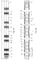
- the casing section having annular barriers has a first end part 23 and a second end part 24, and at least the first end part has at least 1 metre which is free from annular barriers, so that the casing section can be mounted by a rough neck.
- the annular barriers 10 are arranged with a mutual distance D AB of less than 100 cm, preferably less than 50 cm.
- Each annular barrier 10 has a barrier length L B of 1-2.5 metres as shown in Fig. 3B .
- the annular barriers of Fig. 3A have a common longitudinal extension L A of at least 50% of the casing length L C .
- the casing section is shown having a base pipe 25 and each of the expandable metal sleeves 11 surrounds and fastens to the same base pipe 25, forming annular spaces 26 between the expandable metal sleeves 11 and the base pipe 25.
- Each annular space may comprise at least one thermally decomposable compound, which compound is thermally decomposable below a temperature of 400°C and is adapted to generate gas or super-critical fluid upon decomposition.
- the compound comprises nitrogen.
- the compound is selected from a group consisting of: ammonium dichromate, ammonium nitrate, ammonium nitrite, barium azide, sodium nitrate or a combination thereof.
- the compound decomposes at temperatures above 100°C, preferably above 180°C.
- the annular space is pre-pressurised to a pressure above 5 bar, preferably above 50 bar and more preferably above 100 bar, even more preferably above 250 bar.
- the compound is present in the form of a powder, a powder dispersed in a liquid or a powder dissolved in a liquid.
- the base pipe may also have at least one opening 27 opposite each of the expandable metal sleeves 11 for expanding the expandable metal sleeves by allowing pressurised fluid to enter the openings.
- the annular barriers may further comprise a valve or valve assembly in fluid communication with the openings.
- the valve assembly operates between a first position in which fluid is allowed to enter the annular space to expand the expandable metal sleeve and a second position in which the opening is blocked and even permanently blocked.
- the valve assembly may be arranged outside the base pipe and connected to the opening by means of flow lines. The valve assembly may, in the second position, also equalise the pressure within the space with the pressure in the annulus surrounding the well tubular metal structure.
- the expandable metal sleeves 11 are fastened to the base pipe 25 by means of welding, but in another embodiment the expandable metal sleeve may be fastened to the base pipe by means of crimping and/or connection parts connecting the expandable metal sleeves to the base pipe in known ways.
- the expandable metal sleeves 11 of the casing section 3 are connected to form part of the base pipe 25, so that an inner face 28 of the expandable metal sleeves 11 forms part of an inner face 29 of the base pipe 25.
- the expandable metal sleeves thus form the base pipe together with tubular connection parts 31, and the expandable metal sleeves of the casing section are connected indirectly by means of the tubular connection parts.
- the expandable metal sleeves of the casing section are connected directly end to end in an overlapping manner, forming a connection area in the overlapping part.
- the expandable metal sleeves of each casing section having annular barriers may be connected directly or indirectly, forming the connection area 32, as seen in Figs. 4A and 4B .
- a patch may be expanded inside the casing section, so that each end of the patch overlaps the connection area.
- the connection area is an area which is more rigid than the expandable metal sleeves, and the connection area does not expand when the expandable metal sleeves expand.
- the connection areas can be used for support for the patch.
- the connection areas also provide the base pipe with stability both before and after expansion of the expandable metal sleeve.
- the expandable metal sleeve 11 forms an end of the casing section 3, so that the expandable metal sleeve 11 is connected to the next casing section 3 by means of a casing collar 4.
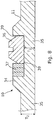
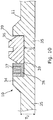
- each expandable metal sleeve 11 comprises a plurality of sealing elements 33 and the expandable metal sleeves also comprises sections 34 having an increased thickness, which sections 34 are expanded less than other sections 35 of the expandable metal sleeve 11.
- each sealing element 33 comprises a sealing part 36 and key rings 37 as back-up to the sealing part 36.
- the section 34 having an increased thickness creates a groove 39 in which the sealing part 36 and key rings 37 are arranged.
- the expandable metal sleeve may have a first thickness T1 opposite the groove 39 and a second thickness T2 outside the groove in the other sections 35. So the other sections 35 may have different thicknesses but thicknesses that are smaller than the thickness of section 34 having the increased thickness.
- an intermediate element 38 is arranged between the split ring-shaped retaining element in the form of key rings 37 and the sealing element 36.
- the split ring-shaped retaining element 37 partly overlaps the intermediate element 38.
- the intermediate element 38 may be made of a flexible material and is adapted to maintain the split ring-shaped retaining element 37 in position and function as protection and support of the sealing element 36.
- the split ring-shaped retaining element or key rings 37, the intermediate element 38 and the sealing element 36 are placed in the groove 39 between the first and second projections, i.e. sections 34.
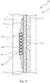
- each sealing element 33 comprises a coiled spring or coiled springs 41 underneath a sealing sleeve 42 having an aperture 43. All the components of the sealing elements 33 in Fig. 9 are of metal and are thus very suitable in high temperature wells.
- the expandable metal sleeve 11 has a first end 14 and a second end 15 and an outer face 16 facing the wellbore/borehole.
- the annular barrier 10 comprises a first end part 17 having a first end 17A connected to the first end 14 of the expandable metal sleeve and a second end 17B for being mounted as part of the base pipe 25 of the casing section 3 of the well tubular metal structure 1.
- the annular barrier 10 further comprises a second end part 18 having a first end 18A connected to the second end of the expandable metal sleeve and a second end 18B for being mounted to another annular barrier and as part of the well tubular metal structure.
- the first end 17A of the first end part 17 is connected end to end to the first end 14 of the expandable metal sleeve 11, and the first end 18A of the second end part 18 is connected end to end to the second end 15 of the expandable metal sleeve.
- the second ends 17B, 18B of the end parts are provided with male or female thread connections for being mounted to corresponding male or female thread connections of other annular barriers of the casing sections. Sealing means 46 is provided between the connections.
- the invention also relates to a downhole method for completing a well having a wellbore, in which the well tubular metal structure 1 is mounted from several casing sections 3 of the downhole completion system 100, then the well tubular metal structure is provided in the wellbore, and subsequently the expandable metal sleeves of the annular barriers are expanded to abut the wellbore.
- the expansion may be performed substantially simultaneously by pressurising the well tubular metal structure or may be performed sequentially, e.g. by means of a tool isolating part of the well tubular metal structure opposite the opening(s).
- At least one of the expandable metal sleeves is perforated, e.g. by intervening by means of a perforation tool/gun, creating access of reservoir fluid into the casing sections and into the well tubular metal structure.
- measurements may be performed in order to determine where to perforate, i.e. where the hydro-carbon fluid is present.
- a patch 51 (shown by dotted line in Fig. 1 ) made be inserted by means of a tool and expanded inside the well tubular metal structure opposite of perforated expandable metal sleeve for sealing off the perforations. Subsequently, new perforations across and through the annular barriers can be made to provide access for the hydro-carbon containing fluid to be produced up the well tubular metal structure.
- fluid or well fluid any kind of fluid that may be present in oil or gas wells downhole, such as natural gas, oil, oil mud, crude oil, water, etc.
- gas is meant any kind of gas composition present in a well, completion, or open hole
- oil is meant any kind of oil composition, such as crude oil, an oil-containing fluid, etc.
- Gas, oil, and water fluids may thus all comprise other elements or substances than gas, oil, and/or water, respectively.
- casing string or well tubular metal structure any kind of pipe, tubing, tubular, liner, string etc. used downhole in relation to oil or natural gas production.
- a downhole tractor can be used to push the tool all the way into position in the well.
- the downhole tractor may have projectable arms having wheels, wherein the wheels contact the inner surface of the casing for propelling the tractor and the tool forward in the casing.
- a downhole tractor is any kind of driving tool capable of pushing or pulling tools in a well downhole, such as a Well Tractor®.
Landscapes
- Life Sciences & Earth Sciences (AREA)
- Engineering & Computer Science (AREA)
- Geology (AREA)
- Mining & Mineral Resources (AREA)
- Physics & Mathematics (AREA)
- Environmental & Geological Engineering (AREA)
- Fluid Mechanics (AREA)
- General Life Sciences & Earth Sciences (AREA)
- Geochemistry & Mineralogy (AREA)
- Earth Drilling (AREA)
Priority Applications (1)
| Application Number | Priority Date | Filing Date | Title |
|---|---|---|---|
| EP18154379.4A EP3299575A3 (de) | 2018-01-31 | 2018-01-31 | Bohrlochabschlusssystem und verfahren |
Applications Claiming Priority (1)
| Application Number | Priority Date | Filing Date | Title |
|---|---|---|---|
| EP18154379.4A EP3299575A3 (de) | 2018-01-31 | 2018-01-31 | Bohrlochabschlusssystem und verfahren |
Publications (2)
| Publication Number | Publication Date |
|---|---|
| EP3299575A2 true EP3299575A2 (de) | 2018-03-28 |
| EP3299575A3 EP3299575A3 (de) | 2018-09-05 |
Family
ID=61132124
Family Applications (1)
| Application Number | Title | Priority Date | Filing Date |
|---|---|---|---|
| EP18154379.4A Withdrawn EP3299575A3 (de) | 2018-01-31 | 2018-01-31 | Bohrlochabschlusssystem und verfahren |
Country Status (1)
| Country | Link |
|---|---|
| EP (1) | EP3299575A3 (de) |
Cited By (3)
| Publication number | Priority date | Publication date | Assignee | Title |
|---|---|---|---|---|
| WO2020104671A1 (en) * | 2018-11-23 | 2020-05-28 | Welltec Oilfield Solutions Ag | An annular barrier |
| EP3667014A1 (de) * | 2018-12-13 | 2020-06-17 | Welltec Oilfield Solutions AG | Ringförmige barriere |
| WO2022157175A1 (en) * | 2021-01-25 | 2022-07-28 | Interwell Norway As | Well tool device for injecting a fluid through a hole in a well bore |
Family Cites Families (4)
| Publication number | Priority date | Publication date | Assignee | Title |
|---|---|---|---|---|
| FR2918700B1 (fr) * | 2007-07-12 | 2009-10-16 | Saltel Ind Soc Par Actions Sim | Procede de chemisage d'un puits ou d'une canalisation au moyen d'une vessie gonflable. |
| FR2996247B1 (fr) * | 2012-10-03 | 2015-03-13 | Saltel Ind | Procede de fracturation hydraulique et materiel correspondant |
| EP2853681A1 (de) * | 2013-09-30 | 2015-04-01 | Welltec A/S | Wärmeexpandierte ringförmige Barriere |
| EP3061901A1 (de) * | 2015-02-27 | 2016-08-31 | Saltel Industries | Vorrichtung zum brechen oder erneuten brechen eines bohrlochs und zugehöriges herstellungsverfahren |
-
2018
- 2018-01-31 EP EP18154379.4A patent/EP3299575A3/de not_active Withdrawn
Non-Patent Citations (1)
| Title |
|---|
| None |
Cited By (4)
| Publication number | Priority date | Publication date | Assignee | Title |
|---|---|---|---|---|
| WO2020104671A1 (en) * | 2018-11-23 | 2020-05-28 | Welltec Oilfield Solutions Ag | An annular barrier |
| EP3667014A1 (de) * | 2018-12-13 | 2020-06-17 | Welltec Oilfield Solutions AG | Ringförmige barriere |
| WO2022157175A1 (en) * | 2021-01-25 | 2022-07-28 | Interwell Norway As | Well tool device for injecting a fluid through a hole in a well bore |
| US12416217B2 (en) | 2021-01-25 | 2025-09-16 | Interwell Norway As | Well tool device for injecting a fluid through a hole in a well bore |
Also Published As
| Publication number | Publication date |
|---|---|
| EP3299575A3 (de) | 2018-09-05 |
Similar Documents
| Publication | Publication Date | Title |
|---|---|---|
| US9410412B2 (en) | Multizone frac system | |
| US10480276B2 (en) | Wellbore plug isolation system and method | |
| US5390742A (en) | Internally sealable perforable nipple for downhole well applications | |
| US5228518A (en) | Downhole activated process and apparatus for centralizing pipe in a wellbore | |
| EP3225776B1 (de) | Automatische paketpackvorrichtung und einstellverfahren dafür | |
| EP3415711A1 (de) | Bohrloch-patch-einstellwerkzeug | |
| US10018013B2 (en) | Method and apparatus for treating a well | |
| EP3146144B1 (de) | Bohrlochstrang zum bohren durch eine unterdruckzone | |
| US5346016A (en) | Apparatus and method for centralizing pipe in a wellbore | |
| US9523266B2 (en) | System to perforate a cemented liner having lines or tools outside the liner | |
| US10648323B2 (en) | Apparatus and method for locating and setting a tool in a profile | |
| WO2014100072A1 (en) | Expandable downhole seat assembly | |
| US20160273298A1 (en) | Annular barrier with passive pressure compensation | |
| EP3299575A2 (de) | Bohrlochabschlusssystem und verfahren | |
| US4936387A (en) | Method and apparatus for completion of a horizontal well | |
| EP3475522B1 (de) | Bohrlochbohrsystem | |
| EP4028634B1 (de) | Ringförmiges barrierensystem | |
| US12460522B2 (en) | Collet baffle, a tool incorporating same, and a system and method incorporating same, for perforating and fracking a wellbore not having initial ports or sliding sleeves | |
| EP3990746B1 (de) | Ringförmige barriere mit pressverbindungen | |
| US20180066486A1 (en) | Top set liner hanger and packer with hanger slips above the packer seal | |
| US10344553B2 (en) | Wellbore completion apparatus and methods utilizing expandable inverted seals | |
| WO2023220800A1 (en) | A collet baffle, a tool incorporating same, and a system and method incopora ting same, for perfora ting and fracking a wellbore not having intial ports or sliding sleeves | |
| WO2026052762A1 (en) | A downhole packer assembly | |
| CA3159229A1 (en) | A collet baffle, a tool incorporating same, and a system and method incorporating same, for perforating and fracking a wellbore not having intial ports or sliding sleeves | |
| EP3249152A1 (de) | Bohrlochsystem zur schadensbehebenden behandlung |
Legal Events
| Date | Code | Title | Description |
|---|---|---|---|
| PUAI | Public reference made under article 153(3) epc to a published international application that has entered the european phase |
Free format text: ORIGINAL CODE: 0009012 |
|
| AK | Designated contracting states |
Kind code of ref document: A2 Designated state(s): AL AT BE BG CH CY CZ DE DK EE ES FI FR GB GR HR HU IE IS IT LI LT LU LV MC MK MT NL NO PL PT RO RS SE SI SK SM TR |
|
| AX | Request for extension of the european patent |
Extension state: BA ME |
|
| PUAL | Search report despatched |
Free format text: ORIGINAL CODE: 0009013 |
|
| AK | Designated contracting states |
Kind code of ref document: A3 Designated state(s): AL AT BE BG CH CY CZ DE DK EE ES FI FR GB GR HR HU IE IS IT LI LT LU LV MC MK MT NL NO PL PT RO RS SE SI SK SM TR |
|
| AX | Request for extension of the european patent |
Extension state: BA ME |
|
| RIC1 | Information provided on ipc code assigned before grant |
Ipc: E21B 33/124 20060101ALI20180731BHEP Ipc: E21B 43/10 20060101AFI20180731BHEP Ipc: E21B 33/127 20060101ALI20180731BHEP |
|
| STAA | Information on the status of an ep patent application or granted ep patent |
Free format text: STATUS: THE APPLICATION HAS BEEN WITHDRAWN |
|
| 18W | Application withdrawn |
Effective date: 20180917 |